Table of Contents
Advertisement
Quick Links
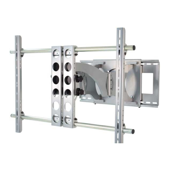
Thank you for choosing the Sanus Systems VisionMount™ VMDD26. It mounts most flat panel televisions up to 1600 cm (63 in),
tilts the TV +5° to -15°, swivels ± 75°, rolls ± 6°, and extends 654 mm (25.75 in) from the wall.
Do not use this product for any purpose not explicitly specified by Sanus Systems. Improper installation may
cause property damage or personal injury. If you do not understand these directions, or have doubts about the
safety of the installation, contact Sanus Systems Customer Service or call a qualified contractor. Sanus Systems is
not liable for damage or injury caused by incorrect mounting, assembly, or use.
The TV must not exceed 79.4 kg (175 lb) or 1600 cm (63 in). The wall must support five times the weight of the TV
plus the wall mount. If necessary, reinforce the structure before installing the unit. Failure to provide adequate
structural strength may result in serious personal injury or damage to equipment.
The supplied wall mounting hardware is not for metal stud, concrete, brick, or block walls. If you are uncertain
about the nature of your wall, consult an installation contractor. The installer must verify the safety of any
installation method or use of hardware not provided by or recommended by Sanus Systems.
Supplied Parts and Hardware
Make sure all parts are included and undamaged. Never use defective parts. If hardware is damaged or missing, contact your local
hardware store or Sanus Systems. Before returning products to the point of purchase, contact Sanus Systems. Replacement parts
for products purchased through authorized dealers are shipped directly to you.
[01] x 1
[04] x 2
Sanus Systems 2221 Hwy 36 West, St Paul, MN 55113 USA • (6901-100015 <01>)
USA Customer Service: 1-800-359-5520 • info@sanus.com • www.sanus.com
VMDD26
WARNING
[02] x 1
[05] x 2
3/16 in
[03] x 2
[06] x 4
Advertisement
Table of Contents

Related Manuals for Sanus VisionMount VMDD26


Summary of Contents for Sanus VisionMount VMDD26
-
Page 1: Supplied Parts And Hardware
VMDD26 Thank you for choosing the Sanus Systems VisionMount™ VMDD26. It mounts most flat panel televisions up to 1600 cm (63 in), tilts the TV +5° to -15°, swivels ± 75°, rolls ± 6°, and extends 654 mm (25.75 in) from the wall. - Page 2 [08] x 1 [09] x 20 [07] x 1 5/16 in. [10] x 14 [11] x 4 [12] x 4 1/4-20 x 2.0 in. 5/16-18 x 1 in. 1/4-20 [13] x 4 [14] x 4 [15] x 3 [16] x 4 M4 x 12mm M5 x 12mm M6 x 12mm...
- Page 3 Determine the Bolt diameter required — [17] / [21], [18] / [22], [19] / [23], or [20]/ [24] — by threading each size into the back of the TV. Stop immediately if you encounter any resistance. 1-1: TV with flat back 1-2: TV with curved back or obstruction [17] [29]...
- Page 4 Do not overtighten the Nut [14]. The Vise Assembly [06] should rotate freely around the Carriage Bolt [13]. [06] [13] [14] [05] [04] [05] [04] [06] 6901-100015 <01>...
- Page 5 CAUTION To prevent property damage or injury from an unstable installation, extend the Tubes [04] beyond the outside edges of both Monitor Brackets [05] and tighten the Allen Bolts on Vise Assemblies [06] and [A] of the Arm Assembly [02]. Do not overtighten Vise Assemblies [06] and [A].
- Page 6 CAuTIoN To prevent property damage or personal injury, tighten each Lag Bolt [11] only until the Wall Plate [01] is pulled firmly against the wall. The drywall or other wall material may not exceed 15.8 mm (5/8 in) in thickness. [01] [11] [12]...
- Page 7 Set the tilt tension with the Knobs [K] on the Arm Assembly [02]. The TV freely tilts +5° to -15° without further Knob adjustment. To change the roll ± 6°, loosen the Allen Bolts [B] on the Arm Assembly, position the TV, and retighten the Allen Bolts. [02] [02] CAuTIoN...
- Page 8 CAUTION To avoid injury, do not place your hands or fingers between moveable parts. [03] [16] Leave some slack in the cables to prevent excess tension on the connectors. Do not run cables through any pinch points. Wire Tie Clips [10] can be pressed into holes on the top and bottom of the Arm Assembly [02] or sides of the Preventor [03]. Wire Ties [09] may be threaded through the Wire Tie Clips or holes in the Monitor Brackets [05] to secure the cables.
Need help?
Do you have a question about the VisionMount VMDD26 and is the answer not in the manual?
Questions and answers