Advertisement
Quick Links
RF-TVMFM01_10-0451_QSG_V2_EN_finalLR.pdf 1 8/23/2011 11:56:36 AM
QUICK SETUP GUIDE
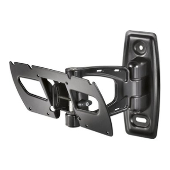
RF-TVMFM01
Thank you for choosing the Rocket sh RF-TVMFM01.
The RF-TVMFM01 TV mount is designed to support a
at-panel TV weighing up to
15.8 kg (35 lbs.).
Package contents
A Arm assembly (1)
M4 bag
B M4 × 12 mm screws (4)
C M4 × 30 mm screws (4)
D M4 washers (4)
E M4 spacers (4)
Hex key bag
M4 bag
F 4 mm (5/32 in.) hex key (1)
M4 × 12 mm
Coach Screw bag
G 8 mm (5/16 in.)× 70 mm
(2 3/4 in.) coach screw (2)
M4 × 30 mm
H Concrete anchor (2)
Cable ties
M4
M4
Hex key bag
Lag Bolt Bag
4 mm
(5/32 in.)
8mm (5/16 in.)× 70 mm (2 3/4 in.)
Cable ties
Tools you will need:
• Stud finder
• Socket wrench with
• Awl
12.7 mm (1/2 in.) socket
• Pencil
or adjustable wrench
• Level
• 5.5 mm (7/32 in.) wood drill bit
• Tape measure
• 9.5 mm (3/8in.) masonry drill bit
• Phillips screwdriver
(concrete only)
• Hammer (concrete only)
• Power drill
1 Install the arm assembly
Option 1: Installing to a wood stud wall
Note: Any material covering the wall must not exceed
16 mm (5/8 in.).
1 Locate the stud. Verify the center of the stud with an awl or
thin nail or use an edge-to-edge stud nder.
2 Level the arm assembly (A) and mark the hole locations.
3 Drill pilot hole to a depth of
75 mm (3 in.) using a
5.5 mm (7/32 in.) diameter drill bit.
4 Align the arm assembly (A) with the
pilot holes, insert the coach screws (G)
through the holes in the arm
assembly, then tighten
the coach screws only until
they are pulled rmly
against the arm assembly.
CAUTION: Avoid potential
injuries or property damage!
DO NOT over-tighten the
coach screws (G).
Wall
203.2 mm
(8 in.)
8 in.
TV
139.7 mm
(5-1/2 in.)
TV shifts
139.7 mm (5-1/2 in.)
in. from the
home position to full extension.
Option 2: Installing to a solid concrete or concrete block wall
1 Level the arm assembly (A) and mark the hole locations.
2 Drill pilot hole to a depth of
75 mm (3 in.)
using a
9.5 mm
(3/8 in.) diameter drill bit.
3 Insert the concrete wall anchors (H) into the pilot holes
and make sure that the anchors are seated ush with
the concrete surface.
4 Align the arm assembly (A) with the anchors, insert
the
coach screws (G) through the holes in the arm assembly,
then tighten the coach screws only until they are pulled
rmly against the arm assembly.
CAUTION: Avoid potential injuries or property damage!
DO NOT over-tighten the coach screws
(G).
75 mm
(3 in.)
2 Attach the mounting hardware
Option 1: For TVs with inset mounting or that require extra space for wires
Install spacers (E), washers (D), and screws (C) into the top two holes in the back of the TV.
Leave a gap between the spacer and the washer and screw.
Note: Only install the hardware in the top two screw holes at this time. The remaining hardware
<16 mm
will be installed in Step 3.
(5/8 in.)
75 mm
(3 in.)
NOTE: If the hole pattern on
your TV is 75 mm x 75 mm the
washers (D) will not be used.
Option 2: For at backed TVs
Install washers (D), and screws (B) into the top two holes in the back of the TV.
Leave a gap between the back of the TV and the washer and screw.
Note: Only install the hardware in the top two screw holes at this time. The remaining hardware
will be installed in Step 3.
CAUTION: To prevent property
damage or personal injury, never
drill into mortar between blocks.
Mount wall plate directly onto the
concrete surface.
NOTE: If the hole pattern on
your TV is 75 mm x 75 mm the
washers (D) will not be used.
Gap
Gap
Advertisement

Subscribe to Our Youtube Channel
Related Manuals for RocketFish RF-TVMFM01


Summary of Contents for RocketFish RF-TVMFM01
- Page 1 DO NOT over-tighten the coach screws (G). Thank you for choosing the Rocket sh RF-TVMFM01. 75 mm The RF-TVMFM01 TV mount is designed to support a Wall (3 in.) at-panel TV weighing up to 15.8 kg (35 lbs.).
- Page 2 © 2011 Best Buy UK Distributions Limited. All rights reserved. Distributed by Best Buy Europe Distributions Limited. 1 Portal Way, London W3 6RS ROCKETFISH is a trademark of BBY Solutions, Inc. Registered in some countries. All other products and brand names are trademarks of their respective owners 6907-002029 <00>...
Need help?
Do you have a question about the RF-TVMFM01 and is the answer not in the manual?
Questions and answers