
Related Manuals for Hobart Welding Products Handler 140


Summary of Contents for Hobart Welding Products Handler 140
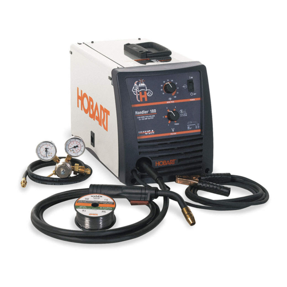
- Page 1 OM-925 217 694B August 2004 Processes MIG (GMAW) Welding Flux Cored (FCAW) Welding Description Arc Welding Power Source And Wire Feeder Handler 140 / 180 And H-10 Gun Visit our website at www.HobartWelders.com...
- Page 2 From Hobart to You Thank you and congratulations on choosing Hobart. Now you can get the job done and get it done right. We know you don’t have time to do it any other way. This Owner’s Manual is designed to help you get the most out of your Hobart products.
-
Page 3: Table Of Contents
TABLE OF CONTENTS SECTION 1 − SAFETY PRECAUTIONS - READ BEFORE USING ........1-1. - Page 4 TABLE OF CONTENTS SECTION 9 − MIG WELDING (GMAW) GUIDELINES ..........9-1.
-
Page 5: Section 1 − Safety Precautions - Read Before Using
SECTION 1 − SAFETY PRECAUTIONS - READ BEFORE USING som _8/03 1-1. Symbol Usage Means Warning! Watch Out! There are possible hazards with this procedure! The possible hazards are shown in the adjoining symbols. This group of symbols means Warning! Watch Out! possible Y Marks a special safety message. - Page 6 ARC RAYS can burn eyes and skin. BUILDUP OF GAS can injure or kill. D Shut off shielding gas supply when not in use. Arc rays from the welding process produce intense visible and invisible (ultraviolet and infrared) rays D Always ventilate confined spaces or use that can burn eyes and skin.
-
Page 7: Additional Symbols For Installation, Operation, And Maintenance
1-3. Additional Symbols For Installation, Operation, And Maintenance FIRE OR EXPLOSION hazard. MOVING PARTS can cause injury. D Do not install or place unit on, over, or near D Keep away from moving parts such as fans. combustible surfaces. D Keep all doors, panels, covers, and guards D Do not install unit near flammables. -
Page 8: Principal Safety Standards
1-5. Principal Safety Standards Safety in Welding, Cutting, and Allied Processes, ANSI Standard Z49.1, Boulevard, Rexdale, Ontario, Canada (phone: from American Welding Society, 550 N.W. LeJeune Rd, Miami FL 33126 800−463−6727 or in Toronto 416−747−4044, website: www.csa−in- (phone: 305-443-9353, website: www.aws.org). ternational.org). -
Page 9: Section 2 − Consignes De Sécurité − À Lire Avant Utilisation
SECTION 2 − CONSIGNES DE SÉCURITÉ − À LIRE AVANT UTILISATION som_fre 8/03 2-1. Signification des symboles Signifie « Mise en garde. Faire preuve de vigilance. » Cette procédure présente des risques identifiés par les symboles adjacents aux directives. Ce groupe de symboles signifie « Mise en garde. Faire preuve de vigi- lance. - Page 10 LES RAYONS DE L’ARC peuvent cau- LES ACCUMULATIONS DE GAZ peu- ser des brûlures oculaires et cuta- vent causer des blessures ou même nées. la mort. Le rayonnement de l’arc génère des rayons visibles et D Couper l’alimentation en gaz protecteur en cas de invisibles intenses (ultraviolets et infrarouges) suscep- non utilisation.
-
Page 11: Autres Symboles Relatifs À L'installation, Au Fonctionnement Et À L'entretien De L'appareil
2-3. Autres symboles relatifs à l’installation, au fonctionnement et à l’entretien de l’appareil. Risque D’INCENDIE OU D’EXPLO- LES ORGANES MOBILES peuvent SION causer des blessures. D Ne pas placer l’appareil sur une surface inflam- D Se tenir à l’écart des organes mobiles comme les mable, ni au−dessus ou à... -
Page 12: Principales Normes De Sécurité
2-4. Principales normes de sécurité Safety in Welding, Cutting, and Allied Processes, norme ANSI Z49.1, Rexdale, Rexdale (Ontario) Canada M9W 1R3 (téléphone : (800) de l’American Welding Society, 550 N.W. LeJeune Rd, Miami FL 33126 463−6727 ou à Toronto : (416) 747−4044, site Web : www.csa−interna- (téléphone : (305) 443−9353, site Web : www.aws.org). -
Page 13: Section 3 − Definitions
SECTION 3 − DEFINITIONS 3-1. Symbols And Definitions Amperage Voltage Hertz Negative Direct Current Positive Single Phase Input (DC) Output Voltage Input Do Not Switch Gas Metal Arc Wire Feed While Welding Welding (GMAW) SECTION 4 − SPECIFICATIONS 4-1. Specifications A. -
Page 14: Duty Cycle And Overheating
4-2. Duty Cycle And Overheating Duty Cycle is percentage of 10 minutes that unit can weld at rated load without overheating. If unit overheats, thermostat(s) A. 115 VAC Model opens, output stops, and cooling fan runs. Wait fifteen minutes for unit to cool. -
Page 15: Volt-Ampere Curves
4-3. Volt-Ampere Curves The volt-ampere curves show the A. 115 VAC Model minimum and maximum voltage and amperage output capabilities of the welding power source. Curves 30.0 of other settings fall between the curves shown. 25.0 20.0 RANGE4 15.0 RANGE3 RANGE2 RANGE1 10.0... -
Page 16: Section 5 − Installation
SECTION 5 − INSTALLATION 5-1. Installing Welding Gun Drive Assembly Gun Securing Thumbscrew Gun End Loosen thumbscrew. Insert end through opening until it bottoms against drive assembly. Tighten thumbscrew. Welding gun must be inserted completely to prevent leakage of shielding gas. Gun Trigger Leads Insert leads, one at a time, through gun opening on front panel. -
Page 17: Process/Polarity Table
5-3. Process/Polarity Table Cable Connections Process Process Polarity Polarity Cable To Gun Cable To Work GMAW − Solid wire with shield- DCEP − Reverse polarity Connect to positive (+) out- Connect to negative (−) output ing gas put terminal terminal FCAW −... -
Page 18: Installing Gas Supply
5-5. Installing Gas Supply Obtain gas cylinder and chain to running gear, wall, other stationary support so cylinder cannot fall and break off valve. DO NOT use Argon/Mixed gas regulator/flowmeter with CO shielding gas. See Parts List for optional Cylinder Valve gas regulator/flowmeter. -
Page 19: Selecting A Location And Connecting Input Power For 115 Vac Model
5-6. Selecting A Location And Connecting Input Power For 115 VAC Model Rating Label Grounded Receptacle A 115 volt, 20 ampere individual 18 in branch circuit protected (460 mm) time-delay fuses or circuit breaker is required. Plug From Unit Select extension cord of 14 AWG for up to 50 ft (15 m) or 12 AWG for 50 up to 200 ft (61 m). -
Page 20: Selecting A Location And Connecting Input Power For 230 Vac Model
5-7. Selecting A Location And Connecting Input Power For 230 VAC Model Rating Label Supply correct input power. Plug (NEMA 6-50P) Receptacle (NEMA 6-50R) Connect plug to receptacle. Line Disconnect Device 18 in (457 mm) of space for airflow See Section 5-8. Y Special installation may be required where gasoline or volatile liquids are present −... -
Page 21: Electrical Service Guide For 230 Vac Model
5-8. Electrical Service Guide For 230 VAC Model Input Voltage Input Amperes At Rated Output Max Recommended Standard Fuse Or Circuit Breaker Rating In Amperes Circuit Breaker , Time-Delay Normal Operating Min Input Conductor Size In AWG Max Recommended Input Conductor Length In Feet (Meters) (20) Min Grounding Conductor Size In AWG Reference: 1999 National Electrical Code (NEC) -
Page 22: Threading Welding Wire
5-10. Threading Welding Wire Wire Spool Welding Wire Inlet Wire Guide Pressure Adjustment Knob Drive Roll Gun Conduit Cable Lay gun cable out straight. Tools Needed: Hold wire tightly to keep it from unraveling. 4 in (102 mm) 6 in (150 mm) Open pressure assembly. -
Page 23: Section 6 − Operation
SECTION 6 − OPERATION 6-1. Controls DO NOT SWITCH WHILE WELDING NE PAS CHANGER DE PROCÉDÉ P U R G E Ref. 217 617-A Wire Speed Control Voltage Switch Voltage Switch - “Purge” Position The higher the selected number, the In purge position, fan runs but there is no Use control to select a wire feed speed. -
Page 24: Weld Parameter Chart For 115 Vac Model
6-2. Weld Parameter Chart For 115 VAC Model OM-925 Page 20... - Page 25 217 618-A OM-925 Page 21...
-
Page 26: Weld Parameter Chart For 230 Vac Model
6-3. Weld Parameter Chart For 230 VAC Model OM-925 Page 22... - Page 27 217 754-B OM-925 Page 23...
-
Page 28: Section 7 − Maintenance &Troubleshooting
SECTION 7 − MAINTENANCE &TROUBLESHOOTING 7-1. Routine Maintenance Y Disconnect power before maintaining. 3 Months Replace Repair or Clean unreadable replace tighten weld labels. cracked terminals. weld cable. 6 Months Blow out or vacuum inside. During heavy service, clean monthly. 7-2. -
Page 29: Changing Drive Roll Or Wire Inlet Guide
7-4. Changing Drive Roll Or Wire Inlet Guide Inlet Wire Guide Securing Screw Inlet Wire Guide Loosen screw. Slide tip as close to drive rolls as possible without touching. Tighten screw. Drive Roll The drive roll consists of two differ- ent sized grooves. -
Page 30: Cleaning Or Replacing Gun Liner
7-6. Cleaning Or Replacing Gun Liner Tools Needed: Y Disconnect gun from unit. 8 mm / 10mm Head Tube Remove nozzle, contact tip, adapter, gas diffuser, and wire outlet guide. 8 mm 10 mm Remove liner. To Reassemble Gun: Insert new liner. Install wire outlet guide so that 1/8 Lay gun cable out straight in (3 mm) of liner sticks out. -
Page 31: Replacing Switch And/Or Head Tube
7-7. Replacing Switch And/Or Head Tube Y Turn Off welding power source /wire feeder and disconnect gun. Remove handle locking nut. Slide handle. Remove switch housing. Install new switch and connect leads (polarity is not important). Reassemble in reverse order. If replacing head tube, continue to end of figure. -
Page 32: Troubleshooting Table
7-8. Troubleshooting Table Trouble Remedy Secure power cord plug in receptacle (see Section 5-6). No weld output; wire does not feed; fan does not run does not run. Replace building line fuse or reset circuit breaker if open. Place Power switch in On position (see Section 6-1). Reset welding power source circuit breaker if open. -
Page 33: Section 8 − Electrical Diagram
SECTION 8 − ELECTRICAL DIAGRAM 217 621-A Figure 8-1. Circuit Diagram For 115 VAC Model OM-925 Page 29... - Page 34 217 755-A Figure 8-2. Circuit Diagram For 230 VAC Model OM-925 Page 30...
-
Page 35: Section 9 − Mig Welding (Gmaw) Guidelines
SECTION 9 − MIG WELDING (GMAW) GUIDELINES 9-1. Typical MIG Process Connections Y Weld current can damage electronic parts in vehicles. Disconnect both battery cables before welding on a vehicle. Place work clamp as close to the weld as possible. Regulator/ Flowmeter Wire Feeder/... -
Page 36: Typical Mig Process Control Settings
9-2. Typical MIG Process Control Settings NOTE These settings are guidelines only. Material and wire type, joint design, fitup, position, shielding gas, etc. affect settings. Test welds to be sure they comply to specifications. Material thickness determines weld parameters. 1/8 or 0.125 in Convert Material Thickness to Amperage (A) -
Page 37: Holding And Positioning Welding Gun
9-3. Holding And Positioning Welding Gun NOTE Welding wire is energized when gun trigger is pressed. Before lowering helmet and pressing trigger, be sure wire is no more than 1/2 in (13 mm) past end of nozzle, and tip of wire is positioned correctly on seam. Hold Gun and Control Gun Trigger Workpiece... -
Page 38: Conditions That Affect Weld Bead Shape
9-4. Conditions That Affect Weld Bead Shape NOTE Weld bead shape depends on gun angle, direction of travel, electrode extension (stickout), travel speed, thickness of base metal, wire feed speed (weld current), and voltage. Push Drag Perpendicular GUN ANGLES AND WELD BEAD PROFILES Short Normal Long... -
Page 39: Gun Movement During Welding
9-5. Gun Movement During Welding NOTE Normally, a single stringer bead is satisfactory for most narrow groove weld joints; however, for wide groove weld joints or bridging across gaps, a weave bead or multiple stringer beads works better. Stringer Bead − Steady Movement Along Seam Weave Bead −... -
Page 40: Troubleshooting − Excessive Spatter
9-8. Troubleshooting − Excessive Spatter Excessive Spatter − scattering of molten metal particles that cool to solid form near weld bead. S-0636 Possible Causes Corrective Actions Wire feed speed too high. Select lower wire feed speed. Voltage too high. Select lower voltage range. Electrode extension (stickout) too long. -
Page 41: Troubleshooting − Lack Of Penetration
9-11. Troubleshooting − Lack Of Penetration Lack Of Penetration − shallow fusion between weld metal and base metal. Lack of Penetration Good Penetration S-0638 Possible Causes Corrective Actions Improper joint preparation. Material too thick. Joint preparation and design must provide access to bottom of groove while maintaining proper welding wire extension and arc characteristics. -
Page 42: Troubleshooting − Waviness Of Bead
9-14. Troubleshooting − Waviness Of Bead Waviness Of Bead − weld metal that is not parallel and does not cover joint formed by base metal. S-0641 Possible Causes Corrective Actions Welding wire extends too far out of nozzle. Be sure welding wire extends not more than 1/2 in (13 mm) beyond nozzle. Unsteady hand. -
Page 43: Common Mig Shielding Gases
9-16. Common MIG Shielding Gases This is a general chart for common gases and where they are used. Many different combinations (mixtures) of shielding gases have been developed over the years. The most commonly used shielding gases are listed in the following table. - Page 44 Problem Probable Cause Remedy Wire slipping in drive rolls. Adjust pressure setting on wire feed rolls. Replace worn Welding arc not stable. drive rolls if necessary. Wrong size gun liner or contact tip. Match liner and contact tip to wire size and type. Incorrect voltage setting for selected wire feed speed on Readjust welding parameters.
- Page 45 Notes OM-925 Page 41...
-
Page 46: Main Assembly Parts List & View
SECTION 10 − PARTS LIST Hardware is common and not available unless listed. 803 716-B Figure 10-1. Main Assembly OM-925 Page 42... - Page 47 Item Dia. Part Mkgs. Description Quantity Figure 10-1. Main Assembly ....199 566 DOOR, access ..........
- Page 48 Item Dia. Part Mkgs. Description Quantity Figure 10-1. Main Assembly (Continued) ....196 574 SWITCH, rocker DPST (230 VAC model) ......
- Page 49 802 447 Figure 10-2. H-10 Gun Item Part Description Quantity 195 957 Figure 10-2. H-10 Gun ....169 715 ..NOZZLE, slip type .500 orf flush .
-
Page 50: Optional Drive Rolls/Options Parts List
10-3. Optional Drive Rolls For All Feed Head Assemblies WIRE DIAMETER PART NO. INCHES (mm) 202 925 .023/.025 (.6) and .030/.035 (.8 and .9) 202 926 .030/.035 (.8 and .9) and .045 (1.2 VK Groove) 10-4. Options PART NO. DESCRIPTION REMARKS 770 187 Running Gear/Cylinder Rack... - Page 51 Effective January 1, 2003 5/3/1 WARRANTY applies to all Handler 125, 135 and 175 models, Airforce 250, 250A, 375, 400 Warranty Questions? and 625 models, and Champion 4500 and 10,000 models, Beta-Mig 1800, Champ 1435, 2060, 8500 Call models, Ironman 210 and 250 models, Stickmate models, Tigmate models, and HSW-15 and 1-877-HOBART1 HSW-25 spot welder models effective with Serial No.
- Page 52 Welding Process Handbooks Call 1-877-Hobart1 Contact the Delivering Carrier to: File a claim for loss or damage during shipment. For assistance in filing or settling claims, contact your distributor and/or equipment manufacturer’s Transportation Department. PRINTED IN USA 2003 Hobart Welding Products. 1/03...
Need help?
Do you have a question about the Handler 140 and is the answer not in the manual?
Questions and answers
Why does Hobart sell this welder( 140) with a weak circuit board in the transistors and thermistor? I bought this welder in 2008 and have had to replace these items several times. A new circuit board is around 300$. The welder cost me 500$ at northern tools. Very unsatisfactory! Is there a recall on this particular welder?