
Related Manuals for Hobart Welding Products Champion 10,000


Summary of Contents for Hobart Welding Products Champion 10,000
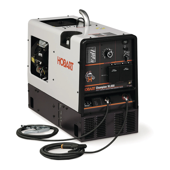
- Page 1 OM-945 194 047U September 2004 Processes Stick (SMAW) Welding Description Engine Driven Welding Generator Champion 10,000 Visit our website at www.HobartWelders.com...
- Page 2 From Hobart to You Thank you and congratulations on choosing Hobart. Now you can get the job done and get it done right. We know you don’t have time to do it any other way. This Owner’s Manual is designed to help you get the most out of your Hobart products.
-
Page 3: Table Of Contents
TABLE OF CONTENTS SECTION 1 − SAFETY PRECAUTIONS − READ BEFORE USING ........1-1. - Page 4 TABLE OF CONTENTS SECTION 9 − MAINTENANCE − (KOHLER-POWERED UNITS) ........9-1.
-
Page 5: Section 1 − Safety Precautions − Read Before Using
SECTION 1 − SAFETY PRECAUTIONS − READ BEFORE USING rom _nd_8/03 Y Warning: Protect yourself and others from injury — read and follow these precautions. 1-1. Symbol Usage Means Warning! Watch Out! There are possible hazards with this procedure! The possible hazards are shown in the adjoining symbols. -
Page 6: Engine Hazards
WELDING can cause fire or explosion. HOT PARTS can cause severe burns. D Allow cooling period before maintaining. Welding on closed containers, such as tanks, drums, or D Wear protective gloves and clothing when working on pipes, can cause them to blow up. Sparks can fly off from the welding arc. -
Page 7: Compressed Air Hazards
STEAM AND HOT COOLANT can burn. BATTERY ACID can BURN SKIN and EYES. D Do not tip battery. D If possible, check coolant level when engine is cold to avoid scalding. D Replace damaged battery. D Always check coolant level at overflow tank, if pres- D Flush eyes and skin immediately with water. -
Page 8: California Proposition 65 Warnings
READ INSTRUCTIONS. ARC WELDING can cause interference. D Use only genuine MILLER/Hobart replacement D Electromagnetic energy can interfere with sensitive parts. electronic equipment such as microprocessors, computers, and computer-driven equipment such as D Perform engine and air compressor (if applicable) robots. -
Page 9: Section 2 − Consignes De Sécurité − Lire Avant Utilisation
SECTION 2 − CONSIGNES DE SÉCURITÉ − LIRE AVANT UTILISATION rom_fre 8/03 Y Avertissement: Protégez vous et les autres des blessures − lisez et suivez ces précautions. 2-1. Signification des symboles Signifie Mise en garde ! Soyez vigilant ! Cette procédure Ce groupe de symboles si- présente des risques de danger ! Ceux-ci sont identifiés par gnifie Mise en garde ! -
Page 10: Dangers Existant En Relation Avec Le Moteur
Suivre les recommandations dans OSHA 1910.252(a)(2)(iv) et NFPA 51B LES ACCUMULATIONS DE GAZ ris- pour les travaux à chaud et avoir de la surveillance et un extincteur à proxi- quent de provoquer des blessures ou mité. même la mort. DES PARTICULES VOLANTES peuvent blesser les yeux. -
Page 11: Dangers Liés À L'air Comprimé
D Pour empêcher tout démarrage accidentel pendant les travaux d’entretien, L’EXPLOSION DE LA BATTERIE peut débrancher le câble négatif (−) de batterie de la borne. RENDRE AVEUGLE. D Ne pas approcher les mains, cheveux, vêtements lâches et outils des orga- nes mobiles. -
Page 12: Principales Normes De Sécurité
LE SURCHAUFFEMENT peut endom- LIRE LES INSTRUCTIONS. mager le moteur électrique. D Utiliser seulement les pièces de rechange d’origine. D Effectuer la maintenance du moteur et du compres- D Arrêter ou déconnecter l’équipement avant de dé- seur (si applicable) suivant ce manuel et le manuel du marrer ou d’arrêter le moteur. -
Page 13: Section 3 − Definitions
SECTION 3 − DEFINITIONS 3-1. Symbol Definitions Fast Fast/Slow Stop Engine Slow (Idle) (Run, Weld/Power) (Run/Idle) Read Operator’s Start Engine Amperes Volts Manual Engine Oil Fuel Battery (Engine) Engine Check Valve Engine Choke Circuit Breaker Temperature Clearance Alternating Current Positive Negative Output (AC) -
Page 14: Dimensions, Weights, And Operating Angles
4-2. Dimensions, Weights, and Operating Angles Dimensions Height 33-1/2 in (851 mm) Width 18-1/2 in (470 mm) Y Do not exceed tilt angles or engine could Y Do not exceed tilt angles or engine could Depth 38 in (965 mm) be damaged or unit could tip. -
Page 15: Fuel Consumption (All Models)
4-4. Fuel Consumption (All Models) 197 254 4-5. Duty Cycle Duty cycle is the percentage of 10 minutes that unit can weld at rated load without overheating. Y Exceeding duty cycle can damage unit void warranty. Continuous Welding 100% Duty Cycle at 170 Amperes CC/DC 6 Minutes Welding 4 Minutes Resting 3 Minutes Welding... -
Page 16: Volt-Ampere Curves
4-6. Volt-Ampere Curves The volt-ampere curve shows the minimum and maximum voltage and amperage output capabilities of the welding generator. Curves of all other settings fall between the curves shown. 197 253 Notes MATERIAL THICKNESS REFERENCE CHART 24 Gauge (.025 in) 22 Gauge (.031 in) 20 Gauge (.037 in) 18 Gauge (.050 in) -
Page 17: Section 5 − Installation
SECTION 5 − INSTALLATION 5-1. Installing Welding Generator Y Do not weld on base. Welding on base can cause fuel tank fire or explosion. Bolt unit down using holes provided in base. Movement Y Always securely fasten weld- Y Do not lift unit from end. ing generator onto transport vehicle or trailer and comply with all DOT and other applica-... -
Page 18: Engine Prestart Checks (Onan-Powered Units)
5-2. Engine Prestart Checks (Onan-Powered Units) Check all fluids daily. Engine must be cold and on a level surface. Unit is shipped with 10W30 engine oil. Engine stops if oil pressure gets too low. Follow run-in procedure in engine manual. Full This unit has a low oil pressure shutdown switch. -
Page 19: Activating The Dry Charge Battery (If Applicable)
5-4. Activating The Dry Charge Battery (If Applicable) Remove battery from unit. Eye Protection − Safety Glasses Or Face Shield Rubber Gloves Vent Caps Sulfuric Acid Electrolyte (1.265 Specific Gravity) Well Fill each cell with electrolyte to bottom of well (maximum). Y Do not overfill battery cells. -
Page 20: Connecting The Battery
5-5. Connecting the Battery Y Connect negative (−) cable last. − Tools Needed: 1/2 in Ref. 202 069-A / Ref. 802 341 / Ref. S-0756-D 5-6. Installing Exhaust Pipe Y Engine backfire can cause se- vere burns or other injuries. Do not point exhaust pipe to- ward control panel. -
Page 21: Connecting To Weld Output Terminals
5-7. Connecting to Weld Output Terminals Negative (−) Weld Output Terminal Positive (+) Weld Output Terminal For Direct Current Electrode Posi- tive (DCEP), connect work cable to Negative (−) terminal and electrode holder cable Positive terminal. For Direct Current Electrode Nega- tive (DCEN), reverse... -
Page 22: Amperage Selection Table For Stick (Smaw) Electrodes
5-9. Amperage Selection Table For Stick (SMAW) Electrodes Use table on front panel to se- lect correct amperage for the electrode being used. Ref. 202 069-A Notes Work like a Pro! Pros weld and cut safely. Read the safety rules at the beginning of this manual. -
Page 23: Section 6 − Operating The Welding Generator
SECTION 6 − OPERATING THE WELDING GENERATOR NOTE If the unit is extremely overloaded, weld and generator power will stop. Turn unit off and restart to reset the generator protection circuit and restore weld and generator power output. If the rated output of the unit is exceeded, engine speed may vary rapidly until the weld or generator power load is reduced. -
Page 24: Section 7 − Operating Auxiliary Equipment
SECTION 7 − OPERATING AUXILIARY EQUIPMENT NOTE If the unit is extremely overloaded, weld and generator power will stop. Turn unit off and restart to reset the generator protection circuit and restore weld and generator power output. If the rated output of the unit is exceeded, engine speed may vary rapidly until the weld or generator power load is reduced. -
Page 25: Optional Generator Power Receptacles
7-2. Optional Generator Power Receptacles Y If unit does not have GFCI re- ceptacles, GFCI- protected extension cord. Combined output of all receptacles limited to 10 kVA/kW rating of the generator. GFCI Receptacle Option 120 V 20 A AC GFCI Recep- tacles GFCI2 and GFCI3 GFCI2 and GFCI3 supply 60 Hz single-phase power at weld/power... -
Page 26: Section 8 − Maintenance (Onan-Powered Units)
SECTION 8 − MAINTENANCE (ONAN-POWERED UNITS) 8-1. Routine Maintenance (Onan-Powered Units) Note Follow the storage procedure in the engine owner’s manual if the unit will not be used for an extended period. Y Stop engine before maintaining. See Engine Manual and Maintenance Label for Recycle important start-up, service, and storage informa- engine... -
Page 27: Maintenance Label (Onan-Powered Units)
Every 500 h Service welding generator Repair or brushes and slip rings. Service replace cracked more often in dirty conditions.* cables. Check valve clearance.* Every 1000 h Blow vacuum inside. During heavy service, clean monthly. 8-2. Maintenance Label (Onan-Powered Units) OM-945 Page 23... -
Page 28: Servicing Air Cleaner (Onan-Powered Units)
8-3. Servicing Air Cleaner (Onan-Powered Units) Y Stop engine. Y Do not run engine without air cleaner or with dirty element. Wrapper (Foam Element) Wash wrapper with soap and water solution. Allow wrapper to air dry completely. Element Replace element if dirty, oily, or damaged. -
Page 29: Overload Protection (Onan-Powered Units)
8-4. Overload Protection (Onan-Powered Units) Tools Needed: Y Stop engine. Disconnect nega- tive (−) battery cable. If the unit is extremely over- loaded, weld and generator pow- 3/8 in er will stop. Turn unit off and re- start to reset the generator protection circuit and restore weld and generator power output. -
Page 30: Changing Engine Oil, Oil Filter, And Fuel Filter (Onan-Powered Units)
8-6. Changing Engine Oil, Oil Filter, and Fuel Filter (Onan-Powered Units) Y Stop engine and let cool. Oil Drain Valve 1/2 ID x 7 in Hose Oil Filter Change engine oil and filter ac- cording to engine owner’s manual. Y Close valve and valve cap before adding oil and running engine. -
Page 31: Adjusting Engine Speed (Onan-Powered Units)
8-7. Adjusting Engine Speed (Onan-Powered Units) After tuning engine, check engine speeds with a tachometer (see table). If necessary, adjust speeds as follows: 2200 100 rpm Start engine and run until warm. Remove wrapper to access speed 3700 50 rpm adjustments. -
Page 32: Section 9 − Maintenance − (Kohler-Powered Units)
SECTION 9 − MAINTENANCE − (KOHLER-POWERED UNITS) 9-1. Routine Maintenance (Kohler-Powered Units) Note Follow the storage procedure in the engine owner’s manual if the unit will not be used for an extended period. Y Stop engine before maintaining. See Engine Manual and Maintenance Label for Recycle important start-up, service, and storage informa- engine... - Page 33 Every 200 h Change oil filter. See Section Replace fuel filter. See 9-6 and maintenance label. Section 9-6. Check spark plugs. Replace unreadable labels. Every 500 h Service welding generator Repair or replace cracked brushes and slip rings. Service cables. more often in dirty conditions.* Every 1000 h Blow out or vacuum inside.
-
Page 34: Maintenance Label (Kohler-Powered Units)
9-2. Maintenance Label (Kohler-Powered Units) OM-945 Page 30... -
Page 35: Servicing Air Cleaner (Kohler-Powered Units)
9-3. Servicing Air Cleaner (Kohler-Powered Units) Y Stop engine. Y Do not run engine without air cleaner or with dirty element. Wrapper (Foam Element) Wash wrapper with soap and water solution. Allow wrapper to air dry completely. Spread 1 tablespoon SAE 30 oil evenly into wrapper. -
Page 36: Overload Protection (Kohler-Powered Units)
9-4. Overload Protection (Kohler-Powered Units) Y Stop engine. Tools Needed: If the unit is extremely over- loaded, weld and generator pow- er will stop. Turn unit off and re- start to reset the generator 3/8 in protection circuit and restore weld and generator power out- put. -
Page 37: Changing Engine Oil, Oil Filter, And Fuel Filter (Kohler-Powered Units)
9-6. Changing Engine Oil, Oil Filter, and Fuel Filter (Kohler-Powered Units) Y Stop engine and let cool. Oil Drain Valve 1/2 ID x 7 in Hose Oil Filter Change engine oil and filter accord- ing to engine owner’s manual. Y Close valve and valve cap before adding running engine. -
Page 38: Adjusting Engine Speed (Kohler-Powered Units)
9-7. Adjusting Engine Speed (Kohler-Powered Units) After tuning engine, check engine speeds with a tachometer (see table). If necessary, adjust speeds as follows: Start engine and run until warm. 2200 50 rpm Remove wrapper to access speed 3700 50 rpm adjustments. -
Page 39: Section 10 − Troubleshooting
SECTION 10 − TROUBLESHOOTING 10-1. Troubleshooting A. Welding Trouble Remedy No weld output. Check control settings. Check weld connections. Reset circuit breaker CB4 (see Section 8-4 or 9-4). Unit overloaded. Stop unit and reduce load. Restart unit to reset generator protection circuit and resume operation. - Page 40 Trouble Remedy Erratic power output at generator pow- Check fuel level. er ac receptacles. Check engine speed and adjust if necessary (see Section 8-7 or 9-7). Check receptacle wiring and connections. Have Factory Authorized Service Agent check brushes and slip rings. C.
-
Page 41: Section 11 − Electrical Diagram
SECTION 11 − ELECTRICAL DIAGRAM 222129−A Figure 11-1. Circuit Diagram For Welding Generator (Onan And Kohler-Powered Units) OM-945 Page 37... -
Page 42: Section 12 − Generator Power Guidelines
SECTION 12 − GENERATOR POWER GUIDELINES NOTE The views in this section are intended to be representative of all engine-driven welding generators. Your unit may differ from those shown. 12-1. Selecting Equipment Generator Power Receptacles − Neutral Bonded To Frame 3-Prong Plug From Case Grounded Equipment 2-Prong Plug From Double... -
Page 43: Grounding When Supplying Building Systems
12-3. Grounding When Supplying Building Systems Equipment Grounding Terminal Grounding Cable GND/PE Use #10 AWG or larger insulated copper wire. Ground Device Y Ground generator to system earth ground if supplying power to a premises (home, shop, farm) wiring system. Use ground device as stated in electrical codes. - Page 44 12-5. Approximate Power Requirements For Industrial Motors Industrial Motors Rating Starting Watts Running Watts Split Phase 1/8 HP 1/6 HP 1225 1/4 HP 1600 1/3 HP 2100 1/2 HP 3175 Capacitor Start-Induction Run 1/3 HP 2020 1/2 HP 3075 3/4 HP 4500 1400 1 HP...
- Page 45 12-7. Approximate Power Requirements For Contractor Equipment Contractor Rating Starting Watts Running Watts Hand Drill 1/4 in 3/8 in 1/2 in Circular Saw 6-1/2 in 7-1/4 in 8-1/4 in 1400 1400 Table Saw 9 in 4500 1500 10 in 6300 1800 Band Saw 14 in...
- Page 46 12-8. Power Required To Start Motor Motor Start Code AC MOTOR Running Amperage VOLTS AMPS Motor HP CODE Motor Voltage PHASE To find starting amperage: Step 1: Find code and use table to find kVA/HP. If code is not listed, multiply running amperage by six to find starting amperage.
- Page 47 12-10. Typical Connections To Supply Standby Power Y Properly install and ground this equipment according to its Owner’s Manual and national, state, and local codes. Fused Utility Welding Disconnect Electrical Generator Transfer Switch Switch Service Output (If Required) Essential Loads Y Have only qualified persons perform Switch transfers the electrical load from Connect generator with temporary or perma-...
- Page 48 12-11. Selecting Extension Cord (Use Shortest Cord Possible) Cord Lengths for 120 Volt Loads Y If unit does not have GFCI receptacles, use GFCI-protected extension cord. Maximum Allowable Cord Length in ft (m) for Conductor Size (AWG)* Current Load (Watts) (Amperes) 350 (106) 225 (68)
-
Page 49: Section 13 − Stick Welding (Smaw) Guidelines
SECTION 13 − STICK WELDING (SMAW) GUIDELINES 13-1. Stick Welding Procedure Y Weld current starts when electrode touches work- piece. Y Weld current can damage electronic parts in vehicles. Disconnect both battery cables before welding on a vehicle. Place work clamp as close to the weld as possible. -
Page 50: Electrode And Amperage Selection Chart
13-2. Electrode and Amperage Selection Chart 3/32 6010 5/32 & 3/16 6011 7/32 6010 DEEP MIN. PREP, ROUGH 1/16 HIGH SPATTER 6011 DEEP 5/64 6013 EP,EN GENERAL 3/32 SMOOTH, EASY, 6013 7014 EP,EN FAST 5/32 3/16 LOW HYDROGEN, 7018 STRONG 7/32 FLAT SMOOTH, EASY,... -
Page 51: Positioning Electrode Holder
13-5. Positioning Electrode Holder 10 -30 End View of Work Angle Side View of Electrode Angle GROOVE WELDS 10 -30 End View of Work Angle Side View of Electrode Angle FILLET WELDS S-0060 13-6. Poor Weld Bead Characteristics Large Spatter Deposits Rough, Uneven Bead Slight Crater During Welding Bad Overlap... -
Page 52: Conditions That Affect Weld Bead Shape
13-8. Conditions That Affect Weld Bead Shape NOTE Weld bead shape is affected by electrode angle, arc length, travel speed, and thickness of base metal. Correct Angle Angle Too Large Angle Too Small Drag ELECTRODE ANGLE Spatter Normal Too Long Too Short ARC LENGTH Normal... -
Page 53: Butt Joints
13-10. Butt Joints Tack Welds Prevent edges of joint from drawing together ahead of electrode by tack welding the materials in position be- fore final weld. Square Groove Weld Good for materials up to 3/16 in (5 mm) thick. Single V-Groove Weld Good for materials 3/16 −... -
Page 54: Weld Test
13-13. Weld Test Vise Weld Joint Hammer Strike weld joint in direction shown. A good weld bends over but does not break. 2 To 3 in (51-76 mm) 2 To 3 in (51-76 mm) 1/4 in (6.4 mm) S-0057-B 13-14. Troubleshooting − Porosity Porosity −... -
Page 55: Troubleshooting − Incomplete Fusion
13-16. Troubleshooting − Incomplete Fusion Incomplete Fusion − failure of weld metal to fuse completely with base metal or a preceeding weld bead. Possible Causes Corrective Actions Insufficient heat input. Increase amperage. Select larger electrode and increase amperage. Improper welding technique. Place stringer bead in proper location(s) at joint during welding. -
Page 56: Troubleshooting − Burn-Through
13-19. Troubleshooting − Burn-Through Burn-Through − weld metal melting completely through base metal resulting in holes where no metal remains. Possible Causes Corrective Actions Excessive heat input. Select lower amperage. Use smaller electrode. Increase and/or maintain steady travel speed. 13-20. Troubleshooting − Waviness Of Bead Waviness Of Bead −... - Page 57 Notes OM-945 Page 53...
-
Page 58: Section 14 − Parts List
SECTION 14 − PARTS LIST Hardware is common and Kohler not available unless listed. only 44 − FIG 14−2 20 − FIG 14−3 802 343−L Figure 14-1. Main Assembly (Onan Engine Shown) OM-945 Page 54... - Page 59 Item Dia. Part Mkgs. Description Quantity Figure 14-1. Main Assembly ....+193 777 Wrapper ........... . .
- Page 60 Item Dia. Part Mkgs. Description Quantity Figure 14-1. Main Assembly (Continued) ....181 057 Cover, Base ..........
- Page 61 Item Dia. Part Mkgs. Description Quantity Figure 14-2. Panel, Front w/Components (Figure 14-1 Item 47) ....198 122 Stand−off Support, Pc Card .250w/Post&lock .500 .
- Page 62 Item Part Description Quantity Figure 14-3. Generator (Figure 14-1 Item 20) ....+220 832 Generator Assy, Front (consisting of) ......
- Page 63 Effective January 1, 2004 5/3/1 WARRANTY applies to all Handler 125, 135 and 175 models, Airforce 250, 250A, 375, 400 Warranty Questions? and 625 models, and Champion 4500 and 10,000 models, Beta-Mig 1800, Champ 1435, 2060, 8500 Call models, Ironman 210 and 250 models, Stickmate models, Tigmate models, and HSW-15 and 1-877-HOBART1 HSW-25 spot welder models effective with Serial No.
- Page 64 Welding Process Handbooks Call 1-877-Hobart1 Contact the Delivering Carrier to: File a claim for loss or damage during shipment. For assistance in filing or settling claims, contact your distributor and/or equipment manufacturer’s Transportation Department. PRINTED IN USA 2004 Hobart Welding Products. 1/04...
Need help?
Do you have a question about the Champion 10,000 and is the answer not in the manual?
Questions and answers