Table of Contents
Advertisement
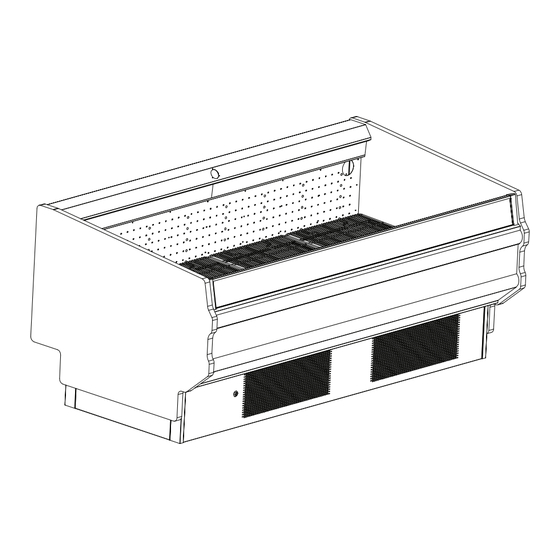
OWZA
Energy Data & Dimensions ...........................2-3
General Information ......................................... 4
Installation ......................................................5-6
Refrigeration Piping ......................................... 7
Plumbing ........................................................... 8
Electrical Connections ..................................... 9
Air Flow, Defrost & Temp Control .................. 10
F R O Z E N F O O D C A S E
I n s t a l l a t i o n & O p e r a t i o n H a n d b o o k
Table of Contents
Use & Maintenance ........................................ 11
Parts Ordering ................................................ 12
Appendix A: Domestic Wiring Diagrams
P074749F
Rev. 2 07/09
Advertisement
Table of Contents

Related Manuals for Hill Phoenix OWZA P074749F


Summary of Contents for Hill Phoenix OWZA P074749F
-
Page 1: Table Of Contents
OWZA F R O Z E N F O O D C A S E I n s t a l l a t i o n & O p e r a t i o n H a n d b o o k Table of Contents Energy Data &... - Page 3 , the safety of our customers and employees, as well as the ongoing performance of our products, are top priorities. To that end, we include important warning messages in all Hill PHOENIX installation and operation handbooks, ac- companied by an alert symbol paired with the word "DANGER", "WARNING", or "CAUTION".
-
Page 4: Energy Data & Dimensions
NERGY OWZA System Requirements Plug Cord Model Volts Phase Style Length OWZA - 8' L14-30P 1 For export cases, a NEMA L6-30 electrical plug is used. Condensing Unit Data (2 units/case) Condenser Fans Frequency Lbs. of Amps Watts Model Volts Phase (Hz) (amps) - Page 5 IMENSIONS MODEL OWZA 6" THERMOPANE GLASS FRONT 43-1/4 in [109.9 cm] 12-7/8 in [32.7 cm] 38-1/2 in 43 in [97.8 cm] [109.2 cm] COIL PLENUM 29-5/8 in [75.3 cm] 13-1/8 in [33.3 cm] 8-7/8 in 7-7/8 in [22.6 cm] [20.0 cm] 33-11/16 in [85.6 cm] 42-9/16 in...
-
Page 6: General Information
Hill PHOENIX for your food merchandising needs. This handbook contains important technical infor- mation and will assist you with the installation and operation of your new Hill PHOENIX display cases. By closely following the instructions, you can expect peak performance; attractive fits and finish; and long case life. -
Page 7: Installation
NSTALLATION MOVING CASES Hill PHOENIX display cases are generally shipped to stores with casters installed on the base frame. The casters make the job of moving cases easier for everyone involved in the ship- ping and installation process, as well as reducing the chance of FRONT damage from raising and lowering cases with ”J”... - Page 8 EFRIGERATION IPING Refrigeration components for OWZA cases are easily acces- The diagram on page 7 illustrates all of the refrigeration sible in the tank and beneath the case. components in the case – the box-shaped dotted line indicates those components that are located within the case tank. The expansion valve and suction line 1/4”...
-
Page 9: Refrigeration Piping
(Refrigeration Piping, cont'd) MODEL Split OWZA Evaporator TANK AREA Bulb Plenum 1/4" 1/4" Access Access Valve Valve Flow Direction Filter Condenser Drier Service Valve Service Valve Compressor Receiver Condenser Fan Flow Direction Dual Pressure Control Filter Condenser Drier Service Valve Service Valve Compressor... -
Page 10: Plumbing
LUMBING The “P” trap assembly – attached to the case at the factory so outlet is specially molded with PVC material and the “P” trap no assembly is required – directs the case drainage to the drain is constructed of PVC. Care should be given to make certain pan. -
Page 11: Electrical Connections
LECTRICAL ONNECTIONS The OWZA comes pre-wired with a NEMA L14-30P twist- tion utilizes on the right-hand controller. lock plug (250 volt, 4-prong). For export models, a NEMA The case is turned ON/OFF via an electric breaker that is L6-30 twist-lock plug (250 volt, 3-prong) is used. located on the electrical junction box, in the left-hand side of the case behind the front kick plate. -
Page 12: Air Flow, Defrost & Temp Control
& T EFROST ONTROL ing the front kick plate and lower front panel, see the trim out DEFROST & TEMPERATURE CONTROLS section of this manual on page 5. OWZA cases are equipped with both Electric (low-temp) and Timed-Off (medium-temp) defrost and can be run in either low- It is important to consult the control setting guidelines shown or medium-temperature defrost modes. -
Page 13: Use & Maintenance
& M AINTENANCE CASE CLEANING CLEANING PROCEDURES Cases are designed to facilitate cleaning. All surfaces pitch to • A periodic cleaning schedule should be established to a deep-drawn drain trough that angles toward the front-center maintain proper sanitation, insure maximum operating ef- of the case where the waste outlet is located for easy access. -
Page 14: Parts Ordering
ARTS RDERING 1. Contact the Service Parts Department at: 1-800-283-1109 2. Provide the following information about the part you are ordering: • Model number and serial number of the case for which the part is intended. • Length of the part (if applicable). •... - Page 15 PPENDIX OMESTIC IRING IAGRAM...
-
Page 20: Appendix B: Export Wiring Diagrams
PPENDIX XPORT IRING IAGRAM... -
Page 25: Appendix C: Controller Information
PPENDIX ONTROLLER NFORMATION... - Page 26 dIXEL Operating Manual 1592020130 DIGITAL CONTROLLER 6. FRONT PANEL COMMANDS XR03CX – XR04CX To display target set point, in programming mode it selects a parameter confirm operation 1. CONTENTS To start a manual defrost Contents __________________________________________________________________________ 1 General warnings ___________________________________________________________________ 1 programming mode General description __________________________________________________________________ 1...
- Page 27 dIXEL Operating Manual 1592020130 Hy Differential: (0,1°C ÷ 25°C) Intervention differential for set point. Compressor Cut IN is SET as the external digital input is disabled again. With the door open, the high and low temperature alarms are disabled. POINT + differential (Hy). Compressor Cut OUT is when the temperature reaches the set point. LS Minimum SET POINT: (-55°C÷SET/-58°F÷SET): Sets the minimum value for the set point..
- Page 28 dIXEL Operating Manual 1592020130 Protection: IP20; Frontal protection: IP65 Start defrost delay 0 ÷ 99 min. Connections: Screw terminal block ≤ 2,5 mm wiring. Power supply: according to the model: 12Vac/dc, ±10%; 24Vac/dc, ±10%; 230Vac ±10%, 50/60Hz, Display during defrost rt –...
-
Page 29: Appendix D: User Set Points
PPENDIX OINTS... - Page 31 Material or Workmanship States Our Entire Liability Whether Based on Tort, Contract or Warranty. We Neither Assume Nor Authorize Any Other Person to Assume for Us Any Other Liability in Connection with Our Product. MAIL CLAIM TO: Hill PHOENIX Hill PHOENIX Display Merchandisers Refrigeration Systems &...
- Page 32 1925 Ruffin Mill Road, Colonial Heights, VA 23834 Due to our commitment to continuous improvement all specifications are subject to change without notice. Hill PHOENIX is a Sustaining Member of the American Society of Quality. Visit our web site at www.hillphoenix.com...
Need help?
Do you have a question about the OWZA P074749F and is the answer not in the manual?
Questions and answers