Advertisement
Quick Links
OPERATOR'S
MANUAL
\
\
\
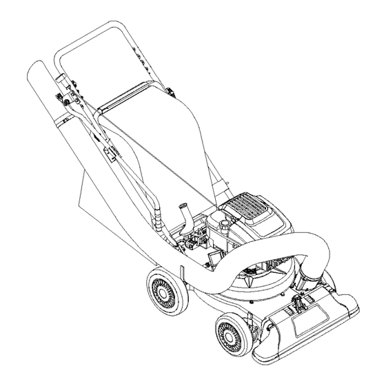
Yard Vacuum
Chi pper/Shredder/
Vacuum/Hose
Model Number
24A-060F063
IMPORTANT:
READ SAFETY RULES AND INSTRUCTIONS
CAREFULLY
Warning:
This unit is equipped with an internal combustion
engine and should not be used on or near any unimproved
forest-
covered, brush-covered
or grass-covered
land unless the engine's exhaust system is equipped with a spark attester
meeting
applicable local or state laws (if any). If a spark arrester is used, it should be maintained in effective working order by the operator.
In the State of California the above is required by law (Section 4442 of the California Public Resources Code). Other states may have
similar laws. Federal laws apply on federal lands. A spark arrester for the muffler is available through your nearest engine authorized
service dealer or contact the service department,
P.O. Box 361131 Cleveland, Ohio 44136-0019.
TROY-BILT
LLC P.O. BOX 361131 CLEVELAND,
OHIO 44136-0019
PRINTED IN U.S.A.
FORM NO. 769-00169
(4/02)
Advertisement

Subscribe to Our Youtube Channel
Related Manuals for Troy-Bilt 24B-060F063


Summary of Contents for Troy-Bilt 24B-060F063
- Page 1 Federal laws apply on federal lands. A spark arrester for the muffler is available through your nearest engine authorized service dealer or contact the service department, P.O. Box 361131 Cleveland, Ohio 44136-0019. TROY-BILT LLC P.O. BOX 361131 CLEVELAND, OHIO 44136-0019 PRINTED IN U.S.A.
- Page 2 You can locate the model number by looking down at the rear of the Yard Vacuum. A sample model plate is explained below. For future reference, please copy the model number and the serial number of the equipment in the space below. Copy the model number here: O11"_.mll"ll'" TROY-BILT Copy the serial number here: mm_az,w_-_mm.m P.O.
- Page 3 SECTION 1: IMPORTANT SAFEOPERATION P RACTICES WARNING: This symbol points out important safety instructions which, if not followed, could endanger the personal safety and/or property of yourself and others. Read and follow all instructions in this manual before attempting to operate this machine. Failure to comply with these instructions may result in personal injury.
- Page 4 i. Never s torethemachine or fuelcontainer Never operate without either the inlet nozzle or insidewhere thereis anopenflame, s park, optional hose attachment properly attached to the or pilotlight(e.g.furnace, w aterheater, machine. Never attempt to attach or change either space heater, c lothes dryer, e tc.) attachment while the engine is running.
- Page 5 understand and follow the warnings and instructions in this manual and on the machine. WARNING - YOUR RESPONSIBILITY: Restrict the use of this power machine to persons who read, ,,," '_%. ,,.._'_ /..SECTION 2: ASSEMBLING YOUR YARD VACUUM IMPORTANT: This unit is shipped without gasoline or oil in the engine.
- Page 6 Attaching TheHandle • Unfold the upper handle until it aligns with the lower handle. Hose • Secure the two handles by tightening the wing nuts (carriage bolts must be seated properly into the handle). See Figure 1 Spring • Remove the hairpin clips from the handle brackets on the Yard Vacuum and remove the carriage bolts and wing nuts from the lower handle.
- Page 7 Attaching TheBlowerChute(IfEquipped) Blower • Grasp blower chute with one hand and slide locking _Chute rod on mounting bracket with other hand toward engine. Use end of mounting bracket as leverage when sliding the locking rod. See Figure 5. • Slip blower chute over rim of the discharge opening Front and release locking rod to secure chute in place.
- Page 8 Chipper Chute HoseHandle Allow twigs and small branches up to 1 1/2" in diameter Used to guide hose assembly when vacuuming. to be fed into the impeller for chipping. Nozzle/HoseVac Handle Blower Chute(if Equipped) The nozzle/hose vac handle is located on top of the When attached to unit the blower chute is used to blow nozzle and it is used to regulate the vacuum between or scatter yard waste such as leaves, pine needles, or...
- Page 9 • Holdbaghandle andbagclipwhileemptying t he contents. Nozzle/Hose Vac Handle • Compress b agopening andfoldinnerflapover (Top Position) opening. • Foldouterflapoverinner flapandinsert b uttons on thebagthrough metal o utlets. Twist t hebuttons t o lockbag. 3u_ons Inner Flap Spring Loaded Pin Bag Handle (First Hole) Outer Flap_ Figure 8...
- Page 10 NozzleHeightAdjustment The nozzle can be adjusted to any six positions, ranging from 5/8" to 4 1/8" ground clearance. The nozzle height has to be adjusted according to the conditions. Move the height adjustment levers forward or backward to adjust the nozzle upwards or downwards.
- Page 11 Maintenance Engine Refer to the separate engine manual for all engine maintenance instructions. • Check engine oil level before each use as instructed in the separate engine manual packed with your unit. Read and follow instructions carefully. • Clean air cleaner every 25 hours under normal conditions or once a season.
- Page 12 • Apply lubricant to the threads of impeller removal tool and then thread the tool into the crankshaft. Stop when the impeller assembly can move on the crankshaft. Housing • Remove the impeller assembly from the crankshaft. Screws\ Unthread the impeller removal tool from the impeller assembly.
- Page 13 SECTION 6: TROUBLESHOOTING Problem Cause Remedy Engine fails to start Spark plug wire disconnected. Connect wire to spark plug. Fuel tank empty or stale fuel. Fill tank with clean, fresh gasoline. Throttle control lever not in correct Move throttle lever to FAST position. starting position.
- Page 14 Model24A-O60F063 16__...
- Page 15 Model24A-O60F063 Ref. Ref. Part No. Part Description Part Description Part No. 712-0161 Hex Lock Nut #10 - 24 710-3025 Hex Cap Screw 5/16-18 x.625 749-0438D Hex Washer Screw 3/8-16 x 1.25 Upper Handle 710-0502A 720-0279 Knob 710-0751 Hex Cap Screw 1/4-20 x .620 712-3004A Flange Lock Nut 5/16-18 731-2484...
- Page 16 Model24A-O60F063 "6 _.dr_ _ _ _22217 __34...
- Page 17 Model24A-O60F063 Ref. Ref. Part No. Part No. Part Description Part Description 664-0095 732-1150 Bag Assembly Torsion Spring RH 681-0154 Nozzle Door Screen Assembly 731-2294 710-1054 Hex Screw 5/16-24 x 1.0 711-1582 Rod .25 x 1.25 Lg 781-0490 Chipper Blade 781-0725A Front Wheel Support Brace 681-0152 Impeller Assembly...
- Page 18 Notes...
- Page 20 LIMITED WARRANTY FOR: TRilI RILT " The limited warranty set forth below is given by Troy-Bilt Troy-Bilt LLC does not extend any warranty for LLC with respect to new merchandise purchased and used products sold or exported outside of the United in the United States, its possessions and territories.
Need help?
Do you have a question about the 24B-060F063 and is the answer not in the manual?
Questions and answers