Advertisement
Advertisement
Table of Contents

Subscribe to Our Youtube Channel
Related Manuals for ProForm XP400 R


Summary of Contents for ProForm XP400 R
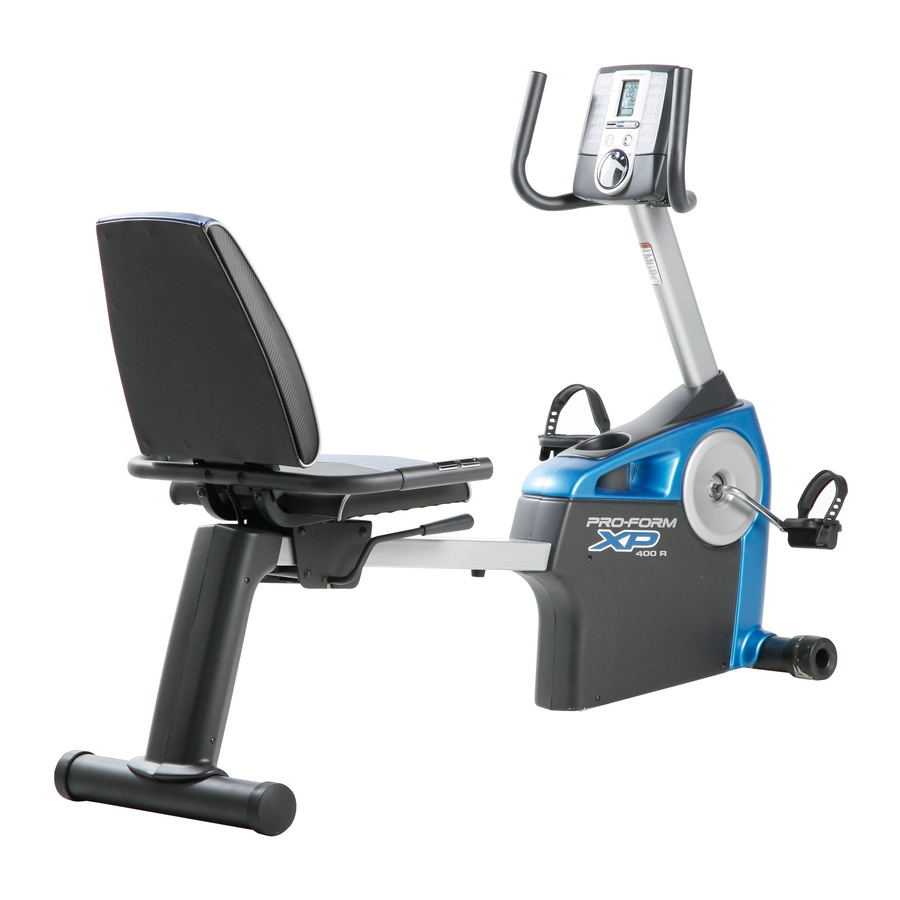
- Page 1 ® Model No. 83t.2t752.0 BIKE EXERCISER Serial No. User's Manual Write the serial number in the space above for reference. Serial Number Decal • Assembly • Operation • Maintenance • Part List and Drawing Sears, Roebuck and Co., Hoffman Estates, IL 60179...
-
Page 2: Table Of Contents
TABLE OF CONTENTS WARNING DECAL PLACEMENT .............. IMPORTANT PRECAUTIONS ..............BEFORE YOU BEGIN ..............ASSEMBLY ................HOW TO USE THE EXERCISE CYCLE ............MAINTENANCE AND TROUBLESHOOTING ........... EXERCISE GUIDELINES ..............PART LIST ................EXPLODED DRAWING ..............ORDERING REPLACEMENT PARTS ..........Back Cover 90 DAY FULL WARRANTY ............ -
Page 3: Important Precautions
IMPORTANT PRECAUTIONS... -
Page 4: Before You Begin
BEFORE YOU BEGIN Congratulations for selecting the new PROFORM ®XP after reading this manual, please see the back cover 400 R exercise cycle. Cycling is one of the most effec- of this manual. To help us assist you, note the product... -
Page 5: Assembly
ASSEMBLY Assembly requires two persons. Place all parts of the exercise cycle in a cleared area and remove the pack- ing materials. Do not dispose of the packing materials until assembly is completed. In addition to the included tools, assembly requires an adjustable wrench o_1_ and a Phillips screwdriver Use the part drawings below to identify the small parts used in assembly. - Page 6 With the help of another person, lift the Frame (1) and place a packing insert (not shown) under the Frame. Have the other person hold the Frame to prevent it from moving from side to side until you complete this step. Attach the Front Stabilizer (3) to the Frame (1) with two M10 x 80ram Patch Screws (47) and two M10 Split Washers (48).
- Page 7 Identify the Right and Left Stabilizer Covers (12, 13), which are marked with "R" and "L" stickers. Attach each Stabilizer Cover (12, 13) to the Rear Stabilizer (2) with two M4 x 16mm Screws (62). Identify the Top Shield (14) and the Upright (4). With the help of another person, slide the Top Shield (14) upward onto the Upright (4).
- Page 8 5. Tip: Avoid pinching the Wire Harness (40) J_Wire Tie during this step. Have another person hold the Upright (4) and the Top Shield (14) near the Frame (1). Locate the wire tie in the Upright and the Wire Harness (40) in the Frame.
- Page 9 The Console (5) can use four 1.5V "D" batteries (not included); alkaline batteries are recom- mended. IMPORTANT: If the Console Battery been exposed to cold temperatures, allow it Cover to warm to room temperature before insert- ing batteries. Otherwise, you may damage the console displays or other electronic...
- Page 10 Tip: Avoid pinching the Pulse Wire (38) during this step. Avoid pinching the Pulse Wire (38) Orient the Pulse Bar (7) as shown. Attach the Pulse Bar to the Seat Carriage (6) with two M10 x 36mm Screws (57) and two M10 Locknuts (58).
- Page 11 11. Orient the Seat (9) as shown. Attach the Seat to the Seat Carriage (6) with four 1/4" x 38ram Patch Screws (61) and four M6 Washers (63). Note: The Patch Screws and the Washers may be preattached to the underside of the Seat.
- Page 12 13. Plug the Pulse Wire (38) into the Pulse Receptacle (39) in the Frame (1). 14. Identify the Right Pedal (44), which is marked with an "R." Using an adjustable wrench, firmly tighten the Right Pedal clockwise into the right side of the Crank (17).
-
Page 13: How To Use The Exercise Cycle
HOW TO USE THE EXERCISE CYCLE HOW TO ADJUST THE PEDAL STRAPS HOW TO MOVE THE EXERCISE CYCLE To adjust the pedal To move the exercise cycle, lift the rear stabilizer until straps, first pull the the exercise cycle can be moved on the front wheels. ends of the straps Carefully move the exercise cycle to the desired loca- Pedal... -
Page 14: Console Diagram
CONSOLE DIAGRAM '9:SB TIME i r'l r'l l U.!_I CALS, WORKOUT START iFitTRAINER RESISTANCE WORKOUTS FEATURES OF THE CONSOLE The console also features the new iFIT Interactive Workout System. The iFIT Interactive Workout System The advanced console offers an array of features enables the console to accept iFIT cards containing designed to make your workouts more effective and workouts designed to help you achieve specific fitness... -
Page 15: How To Use
HOW TO USE THE MANUAL MODE The third section of the display will show Turn on the console. the approximate num- ber of calories you have burned and the To turn on the console, press any button or begin resistance level of the pedaling. -
Page 16: How To Use Trainer Workout
HOW TO USE A TRAINER WORKOUT As you exercise, the display will prompt you Turn on the console. to keep your pedaling pace near the pace To turn on the console, press any button or begin setting for the current pedaling. - Page 17 HOW TO USE A CALORIE GOAL WORKOUT As you exercise, the display will prompt you 1"-- -.,.,,0., b. p Turn on the console. to keep your pedaling pace near the pace To turn on the console, press any button or begin setting for the current pedaling.
- Page 18 HOW TO USE AN IFIT WORKOUT THE INFORMATION MODE The console features an information mode that allows Press any button on the console or begin ped- aling to turn on the console. you to select a unit of measurement for the console and to view usage information for the exercise cycle.
-
Page 19: Maintenance And Troubleshooting
MAINTENANCE AND TROUBLESHOOTING HOW TO ADJUST THE BELT Inspect and tighten all parts of the exercise cycle reg- ularly. Replace any worn parts immediately. If you can feel the pedals slip while you are pedaling, To clean the exercise cycle, use a damp cloth and a even when the resistance is at the highest level, the small amount of mild soap. -
Page 20: Exercise Guidelines
EXERCISE GUIDELINES Burning Fat--To burn fat effectively, you must exer- cise at a low intensity level for a sustained period of time. During the first few minutes of exercise, your body uses carbohydrate calories for energy. Only after the first few minutes of exercise does your body begin to use stored fat calories for energy. -
Page 21: Part List
PART LIST-- Model No. 831.21752.0 R0608A Key No. Qty. Description Key No. Qty. Description Frame Wheel Rear Stabilizer Stabilizer Endcap Front Stabilizer Bumper Upright Right Pedal/Strap Console Left Pedal/Strap M10 x 41 mm Shoulder Screw Seat Carriage Pulse Bar M10 x 80mm Patch Screw Backrest M10 Split Washer Seat... -
Page 22: Exploded Drawing
59 60... -
Page 24: 90 Day Full Warranty
Your Home For repair--in your home--of all major brand appliances, lawn and garden equipment, or heating and cooling systems, no matter made it, no matter who sold For the replacement parts, accessories, and user's manuals that you need to do-it-yourself. For Sears professional installation of home appliances...
Need help?
Do you have a question about the XP400 R and is the answer not in the manual?
Questions and answers
Resistance not working properly, only getting partial resistance. Unhook cable from motor and get about 180 degrees rotation on motor. Appears to be binding issue in the friction housing.
Partial resistance in the ProForm XP400 R could be caused by a binding issue in the friction housing. This may happen if parts like the resistance cable, eddy mechanism, or shoulder screws are misaligned or overtightened. To resolve the binding issue:
1. Inspect the resistance cable (part 51) for proper connection and smooth operation.
2. Check the eddy mechanism (part 16) and pulley/crank (part 17) for any misalignment or obstruction.
3. Ensure shoulder screws (part 46) and other fasteners are not overtightened, which could restrict movement.
4. Adjust or reassemble components as needed to allow free motion of the resistance system.
This should restore full resistance function.
This answer is automatically generated
Can’t get pulse to display heart rate
To fix the heart rate display issue on the ProForm XP400 R, follow these steps:
1. Ensure Proper Grip – Hold the pulse contacts firmly but not too tightly. Gripping too hard may affect readings.
2. Wait for Detection – Keep holding the contacts for at least 15 seconds to allow the heart rate to be detected.
3. Check Positioning – Make sure your hands are positioned correctly on the pulse grips.
4. Clean Contacts – Wipe the pulse grips to remove any sweat or dirt that may interfere with detection.
5. Check for Console Pausing – If the pedals do not move for a few seconds, the console may pause. Resume pedaling to reactivate the display.
6. Restart the Console – If the display does not respond, allow the console to turn off automatically and restart it.
7. Inspect Pulse Sensor Components – Ensure that the pulse wire, pulse receptacle, and connections are secure.
If the issue persists, consider checking the user manual for additional troubleshooting or ordering replacement parts if necessary.
This answer is automatically generated
I need to replace a pedal or both. Prices please