ProForm 390 E User Manual
831.239431
Hide thumbs
Also See for 390 E:
- Manual (28 pages) ,
- Manuel de l'utilisateur (28 pages) ,
- User manual (24 pages)
Table of Contents

Subscribe to Our Youtube Channel
Related Manuals for ProForm 390 E


Summary of Contents for ProForm 390 E
- Page 1 Model No. 831.23943.1 Serial No. ELLIPTICAL Write the serial number in the space above for reference. Manual User's Serial Number Decal • Assembly • Operation • Maintenance • Part List and Drawing Sears, Roebuck and Co. Hoffman Estates, IL 60179...
- Page 2 TABLE OF CONTENTS WARNING DECAL PLACEMENT .............. IMPORTANT PRECAUTIONS ..............BEFORE YOU BEGIN ..............ASSEMBLY ................HOW TO USE THE ELLIPTICAL ............. MAINTENANCE AND TROUBLESHOOTING ........... EXERCISE GUIDELINES ..............PART LIST ................EXPLODED DRAWING ..............ORDERING REPLACEMENT PARTS ..........Back Cover 90 DAY FULL WARRANTY ............
- Page 3 iMPORTANT PRECAUTIONS WARNING: To reduce the risk ofse.ous njory, read a . mportant precaut oos instructions in this manual and all warnings on your elliptical before using your elliptical. Sears assumes no responsibility for personal injury or property damage sustained by or through the use of this product.
-
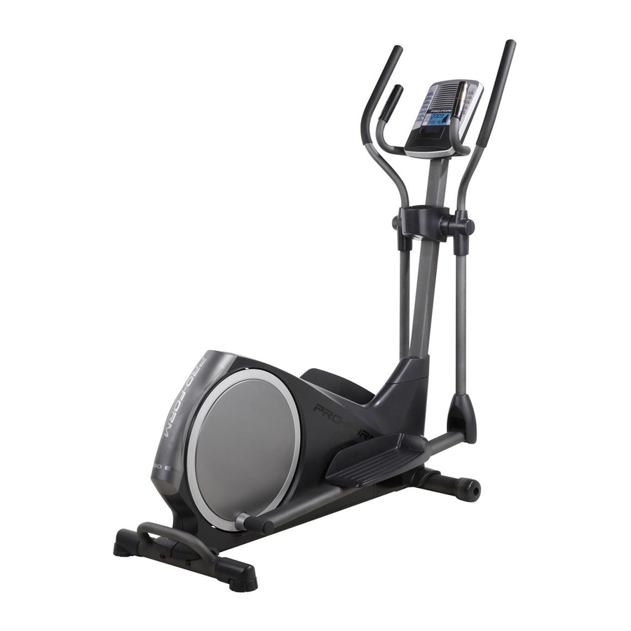
Page 4: Trainer Overview
BEFORE YOU BEGIN Thank you for purchasing the PROFORM ®390 E ellip- manual. To help us assist you, note the product model tical. The 390 E elliptical provides an array of features number and serial number before contacting us. The... - Page 5 ASSEMBLY Assembly requires two persons. Place all parts of the elliptical in a cleared area and remove the packing materials. Do not dispose of the packing materials until assembly is completed. in addition to the included tool(s), assembly requires a Phillips screwdriver _L3======_.
- Page 6 While a second person lifts the rear of the Frame (1), attach the Rear Stabilizer (70) to the Frame with two MIO x 85mm Patch Screws (82). Orient the Front Stabilizer (73) so that the "Front" sticker is facing away from the front of the Frame (1).
- Page 7 Orient the Upright (2) and the Top Shield Cover (37) as shown. Slide the Top Shield Cover upward onto the Upright. Have a second person hold the Upright (2) near Wire the Frame (1). See the inset drawing. Locate the wire tie in the Upright (2).
- Page 8 See the upper drawing. To avoid pinching or damaging the Pulse Wires (28) while you assemble the Handlebar (39), perform the fol- lowing actions: Insert the end of the left Pulse Wire (28) inside the left side of the Handlebar (39). Then, insert the end of the right Pulse Wire (28) inside the right side of the Handlebar (39).
- Page 9 Untie and discard the wire tie attached to the Wire Harness (42). Locate the Pulse Wires (28) inside the left and right sides of the Handlebar (39) and pull them upward out of the Upright (2). While a second person holds the Console (4) near the Upright (2), connect the wires on the Console to the Wire Harness (42) and to the Pulse Wires (28).
- Page 10 Identify the Left and Right Upper Body Arms (8, 9), which are marked with "Left" and "Right" stickers. Orient the Left Upper Body Arm (8) and an Upper Body Leg (6) as shown. Make sure that the hexagonal holes are in the indicated location.
- Page 11 10. Apply a generous amount of the included grease to the axles on the Upright (2). Orient the Left and Right Upper Body Arms (8, 9) as shown, and slide them onto the left and right sides of the Upright (2). Attach each Upper Body Arm (8, 9) with an M8 x 20mm Patch Screw (80) and an M8 Washer (33).
- Page 12 12. See the inset drawing, identify a Pivot Cover A (19), which has hooks, and a Pivot Cover B (22), which has tabs. Press a Pivot Cover A (19) and a Pivot Cover B (22) together around the Right Upper Body Arm (9).
- Page 13 15. Identify the Right Pedal (13), which is marked with a "Right" sticker. Attach the Right Pedal (13) to the Right Pedal Arm (49) with three M10 x 48mm Patch Screws (75) and three M10 Split Washers (78), Make sure to use the center hole and the two outer holes to attach the Right Pedal.
- Page 14 HOW TO USE THE ELLiPTiCAL HOW TO MOVE THE ELLiPTiCAL HOW TO EXERCISE ON THE ELLIPTICAL Due to the size and weight of the elliptical, moving To mount the elliptical, hold the handlebars or the it requires two persons. Stand in front of the ellipti- upper body arms and step onto the pedal that is in the cal, hold the upright, and place one foot against one of lowest position.
- Page 15 C !,...,I L.J '" Mill IIIIII TIME IIIIInnl Iill|llllll mRmm t-t ___ FI mnmm UC,_U HmHJ DISTANCE SPEED RESIST. FEATURES OF THE CONSOLE You can even connect your MP3 player or CD player to the console sound system and listen to your favorite The advanced console offers an array of features music or audio books while you exercise.
-
Page 16: How To Use Manual Mode
HOW TO USE THE MANUAL MODE The lower left display--This display will show the distance (total number of revolutions) that you Turn on the console. have pedaled. Press any button or begin pedaling to turn on the The lower right display--This display will show console. - Page 17 When you are finished exercising, the console tance level is programmed for the next segment, will turn off automatically. the resistance level will flash in the display for a few seconds to alert you. The resistance of the If the pedals do not move for several seconds, a pedals will then change.
- Page 18 MAINTENANCE AND TROUBLESHOOTING Inspect and tighten all parts of the elliptical regularly. Replace any worn parts immediately. To clean the elliptical, use a damp cloth and a small amount of mild soap. IMPORTANT: To avoid damage to the console, keep liquids away from the con- sole and keep the console out of direct sunlight.
- Page 19 HOW TO ADJUST THE REED SWITCH Locate the Reed Switch (58). Loosen, but do not remove, the M4 x 16mm Screw (92). If the console does not display correct feedback, the reed switch should be adjusted. To adjust the reed switch, you must remove the right disc cover and the right pedal disc.
- Page 20 EXERCISE GUiDELiNES Burning Fat--To burn fat effectively, you must exer- cise at a low intensity level for a sustained period of time, During the first few minutes of exercise, your body uses carbohydrate calories for energy, Only after the first few minutes of exercise does your body begin to use stored fat calories for energy, If your goal is to burn fat, adjust the intensity of your exercise until your heart rate is near the lowest number in your training...
-
Page 21: Part List
PART LIST Model No. 831.23943.1 R1010A Key No. Qty. Description Key No. Qty. Description Frame Idler Upright C-magnet Rear Upright Cover Resistance Motor Console Motor Bracket Water Bottle Holder Adjustment Arm Upper Body Leg Clamp Resistance Wheel Reed Switch/Wire Left Upper Body Arm Rear Shield Cover Right Upper Body Arm Foam Grip... - Page 22 r" ._10 77', 92 20 r..o...
- Page 23 /..,, "_ 83_5_. 77 71 ¢o 41" © ¢D © r..o "'-..,,...j 92...
- Page 24 Your Home iiiiiiiiiiiiiiiiiiii; For repair--in your home--of all major brand appliances, lawn and garden equipment, iiiiiiiiiiiiiiiiiii' iiiiiiiiiiiiiiiiiii or heating and cooling systems, no matter who made it, no matter who sold iiiiiiiiiiiiiiiiiii iiiiiiiiiiiiiiiiiii For the replacement parts, accessories, and user's manuals that you need to do-it-yourself. iiiiiiiiiiiiiiiiiii iiiiiiiiiiiiiiiiiii iiiiiiiiiiiiiiiiiii...
Need help?
Do you have a question about the 390 E and is the answer not in the manual?
Questions and answers
where is the reset button on a 390E pro form elliptical located