Table of Contents
Advertisement
Quick Links
Download this manual
See also:
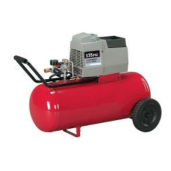
Instruction Manual
Oilfree
Compressors
CPF6020
IMPORTANT
Please make certain that the person who is to use
this equipmer_ earefutty reads and understands
these instructions before starting operations.
The Model and Serial No. p_ate is located on the
frame. Record these numbers in the spaces below
and retain for future r_erence.
Model No,
Type
Serial No.
part No, D20814-004
1iii_!!i%i!!_i!_ii_i_;i_!!i_i_i_i_i;ii_;ii_!_!_!;!!_i_;_!_!_ii_;:_;!;!ii!i!i
¸
Advertisement
Table of Contents

Related Manuals for Porter-Cable CPF4515


Summary of Contents for Porter-Cable CPF4515
- Page 1 Oilfree Compressors CPF6020 IMPORTANT Please make certain that the person who is to use this equipmer_ earefutty reads and understands these instructions before starting operations. The Model and Serial No. p_ate is located on the frame. Record these numbers in the spaces below and retain for future r_erence.
-
Page 2: Safety Instructions
READ AND FOLLOW ALL INSTRUCTIONS, This tool was designed for certain applications. Porter-Cable strongly recommends that this tool NOT be modified and/or used for any application other than for which it was designed. If you have any questions relative to its application DO NOT use the tool until you have written Porter-Cab[e and we have advised you. - Page 3 IMPORTANT SAFETY INSTRUCTIONS (cont'd) SAVE THESE INSTRUCTIONS IMPROPER OPERATION OR MAINTENANCE OF THiS PRODUCT COULD RESULT IN SERIOUS iNJURY PROPERTY DAMAGE, READ UNDERSTAND ALL WARNINGS OPERATING INSTRUCTIONS BEFORE USING THIS EQUIPMENT. HAZARD RISK OF EXPLOSION OR FIRE WHAT CAN HAPPEN HOW TO PREVENT IT IT IS NORMAL FOR ELECTRICAL...
- Page 4 IMPORTANT SAFETY INSTRUCTIONS (cont'd) RISK FROM FLYING OBJECTS HOW TO PREVENT IT WHAT HAPPEN THE COMPRESSED AIR STREAM CAN CAUSE ALWAYS WEAR ANSI Z87.1 APPROVED SAFETY SOFT TISSUE DAMAGE TO EXPOSED SKIN AND GLASSES WITH SIDE SHIELDS WHEN USING THE CAN PROPEL DIRT, CHIPS, LOOSE PARTICLES COMPRESSOR,...
- Page 5 IMPORTANT SAFETY INSTRUCTIONS (cont'd) RISK FROM MOVING PARTS HOW TO PREVENTIT WHAT HAPPEN NEVER OPERATE THE COMPRESSOR WITH MOVING PARTS SUCH PULLEY, GUARDSORCOVERS WHICHAREDAMAGEDOR FLYWHEEL, AND BELT CAN CAUSE SERIOUS REMOVED. INJURY IF THEY COM E INTO CONTACT WITH YOU OR YOUR CLOTHING.
-
Page 6: Duty Cycle
Safety. DUTY CYCLE Porter-Cable air compressors should be operated on not more than a 50% duty cycle. This means an aLrcompressor that pumps air more than 50% of one hour is considered misuse, because the air compressor is undersized for the required air demand. -
Page 7: Description Of Operation
DESCRIPTION OF OPERATION Drain Valve (not shown): The drain valve is located at the base of the air tank and is used to drain condensation at the end of each use. Motor Thermal Overload Protector (not shown): The electric motor has an automatic thermal overload protector. -
Page 8: Installation
INSTALLATION Installing Handles, Wheel, and Rubber Foot (Fig. 2) THE WHEELS AND HANDLE DO NOT PROVIDE ADEQUATE CLEARANCE, STABILITY OR SUPPORT FOR PULLING THE UNIT UP AND DOWN STAIRS OR STEPS. THE UNIT MUST BE LIFTED, OR PUSHED UP A RAMR Submerge handle grip (A) into warm soapy water to make installation easier. - Page 9 Location of the Air Compressor Locate the air compressor in a clean, dry, and well-ventilated area. The air filter must be kept clear of obstructions which could reduce air flow to the air compressor. The air compressor should be located at least 12" away from the wall or other obstructions that will interfere with the flow of air.
- Page 10 GROUNDING INSTRUCTIONS RISK OF ELECTRICAL SHOCK! In the event of a short circuit, grounding reduces the risk of shock by providing an escape wire for the electric current. This air compressor must be properly grounded. If these grounding instructions are not completely understood, or if in doubt as to whether the compressor is propedy grounded, have the installation checked by a qualified electrician.
-
Page 11: Break-In Procedures
BREAK-IN PROCEDURES Serious damage may result if the following break-in instructions are not closely followed, This procedure is required before the air compressor is put into service. (before the hose is installed), the check valve is replaced, or a complete compressor pump is replaced. -
Page 12: Routine Maintenance
MAINTENANCE Unit cycles automatically when power is on. During maintenance, you could be exposed to voltage sources, compressed air, moving parts, or hot surfaces. Personal injuries can occur. Unplug the unit and bleed off all air tank pressure and allow unit to cool before doing any maintenance or repair, Never operate the unit with the belt guard removed. - Page 13 5. Unscrew the check valve using a socket wrench. 6. Check that the valve disc moves freely inside the check valve and that the spring holds the disc in the upper, closed position. The check valve may be cleaned with a strong solvent. 7.
-
Page 14: Troubleshooting
TROUBLESHOOTING GUIDE PERFORMING REPAIRS MAY EXPOSE VOLTAGE SOURCES, MOVING PARTS OR COMPRESSED AIR SOURCES. PERSONAL INJURY MAY OCCUR. PRIOR TO ATTEMPTING REPAIRS, UNPLUG THE AIR COMPRESSOR AND BLEED OFF ALL AIR TANK AIR PRESSURE. PROBLEM CAUSE CORRECTION Excessive tank Pressure switch does not shut Move the pressure switch lever to pressure - safety off motor when compressor... - Page 15 PROBLEM CAUSE CORRECTION Let motor cool off and overload Motor overload protection Motor will not run or restart. switch has tripped. switch will automatically reset. Motor will start automatically when Tank pressure exceeds lressure switch "cut-in" tank pressure drops below "cut-in" pressure of pressure switch.
- Page 16 CAUSE CORRECTION PROBLEM Possibledefectin safetyvalve, Air leak from safety Operate safety valve manually by valve. pulling on ring. If valve still leaks, it should be replaced, Knocking Noise. Malfunctioning check valve. Remove and clean, or reptace. Compressoris Prolonged excessive use of air. Decrease amount of air usage.
-
Page 17: Plumbing Components
ACCESSORIES Accessories can be found at the store from which the unit was purchased or at a local hardware store. FILTERS, REGULATORS, LUBRICATORS UBRICATOR EGULATOR REGULATOR INLINE OILER Regulates air pressure and prlsssur8 downstream removes moisture, oil and into the air line. Controls air other debts from the air line. -
Page 18: Limited Warranty
SERVICE is available by delivering or shipping the defective product or part to any Porter-Cable authorized warranty service location. To determine the nearest authorized warranty service location, call the toll free number, 1-888-559-8550, 24 hours a day, 7 days a week.
Need help?
Do you have a question about the CPF4515 and is the answer not in the manual?
Questions and answers
where is the intake filter located for the cpf4515
The intake filter on the Porter-Cable CPF4515 is part of the air filter kit that includes a new style air filter, head, and o-ring. This assembly has 3/8" threads and should not be used if the compressor head has two holes on the same side.
This answer is automatically generated