LG LMX25964 Series Service Manual
Hide thumbs
Also See for LMX25964 Series:
- Service manual (78 pages) ,
- Owner's manual (44 pages) ,
- Manual del propietario (45 pages)

Related Manuals for LG LMX25964 Series


Summary of Contents for LG LMX25964 Series
- Page 1 REFRIGERATOR SERVICE MANUAL CAUTION BEFORE SERVICING THE UNIT, READ THE SAFETY PRECAUTIONS IN THIS MANUAL. COLOR • STAINLESS MODEL" LMX25964**...
-
Page 2: Table Of Contents
CONTENTS SAFETY PRECAUTIONS ............................... 1. SPECIFICATIONS ................................2. PARTS IDENTIFICATION ..............................3. DISASSEMBLY ................................5-14 REMOVING AND REPLACING REFRIGERATOR DOORS ....................DOOR INSTALLATION ............................... DOOR ....................................TO REMOVE THE DISPENSER ............................DOOR ALIGNMENT ................................FAN AND FAN MOTOR(Evaporator) ..........................ICE FAN SCROLL ASSEMBLY REPLACEMENT ....................... -
Page 3: Specifications
1. SPECIFICATIONS 25 cu. ft ITEMS SPECIFICATIONS ITEMS SPECIFICATIONS DOOR DESIGN Side Rounded VEGETABLE TRAY TransparentDrawer Type COMPRESSOR Linear DIMENSIONS (inches) 353/4X 34 ,/4X 69 3/_ (WXDXH) 25cu.ft EVAPORATOR NET WEIGHT (pounds) 308.65 (25cu.ft) Fin Tube Type COOLING SYSTEM CONDENSER Fan Cooling Spiral Condenser TEMPERATURE... -
Page 4: Parts Identification
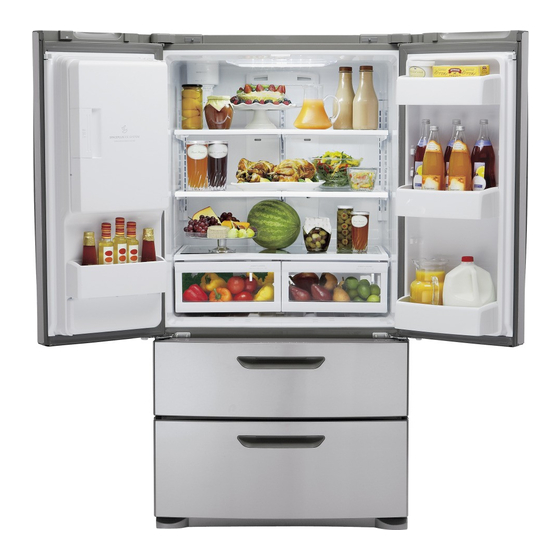
2. PARTS IDENTIFICATION _) ADJUSTABLE REFRIGERATOR SHELVING The refrigerator compartment shelves are adjustable Ice Bank to allow flexibility for storage needs. Ice Door MODULAR DOOR BINS Three interchangeable bins can be arranged to suit your storage needs. _) LED INTERIOR LAMPS _) FIXED DOOR BIN INTERIOR LAMP BOTTLE HOLDER (OPTIONAL) -
Page 5: Disassembly
3. DISASSEMBLY 3=1 REMOVING AND REPLACING REFRIGERATOR DOORS • Removing Refrigerator Door -& CAUTION : Before you begin, unplug the refrigerator. Remove food and bins from doors. 1_Left Door -FIG. 2 1. Disconnect water supply tube by pushing back on the disconnect ring (4).-FIG. 1 2. - Page 6 3-2 DOOR • Door Gasket Replacement 1. Insert gasket bracket clips • Door Gasket Removal 1) Insert gasket bracket edge beneath door frame edge. 1. Remove door frame cover 2) Turn upper gasket bracket spring so that the spring Starting at top of cover and working down, snap cover ends are in the door channel.
-
Page 7: Door Alignment
3-3 DOOR ALIGNMENT 2) Press gasket into channels on the three remaining sides of door. If the space between your doors is uneven, follow the instructions below to align the doors: 1. With one hand, lift up the door you want to raise at middle hinge. -
Page 8: Ice Fan Scroll Assembly Replacement
* Ice Fan Scroll Assembly Replacement LAMP Unplug Refrigerator, or disconnect power at the circuit 1) Remove the plastic guide for slides on left side by breaker. unscrewing phillips head screws. If necessary, remove top shelf or shelves. 2) Pull the grille forward as shown in the second picture. 3) Disconnect wire harness of the grille. -
Page 9: Multi Duct
3-7 MULTI DUCT 3-9 DISPENSER 1) Disconnect funnel and 1. Remove the upper and button assembly by lower Caps by using a pulling down and flat screwdriver, and forward. remove 2 screws. (Figure 16) 2. Disconnect the lead wire on the bottom position. 2) Hold the left and right side Figure 16 of the "Cover Assembly,... - Page 10 3-11 FUNNEL REPLACEMENT 3-14 ICE CORNER DOOR REPLACEMENT 1) Pull up and out on the dispenser cover to remove. 1) Loosen the front screw as shown in the picture. 2) Disconnect the wire harness. 2) Lift up the hinge with one hand. 3) Replace in reverse order.
- Page 11 3-16 AUGER MOTOR COVER 1) After removing the icemaker remove the (5) stainless screws holding the auger motor cover, shown in the picutres below. 2) Grip the bottom of motor cover assembly and pull out it. 3) Disconnect wire harness of motor cover assembly. There is a auger motor on the back, as shown in the picture.
-
Page 12: Door Ice Bin
3-17 HOW TO REMOVE A DOOR ICE BIN 3-18 HOW TO INSERT A DOOR ICE BIN 1) Grip the handles, as shown in the picture. 1) Insert the Ice Bin, slightly tilting it to avoid touching the Icemaker. (especially, ice maker lever) 2) Lift the lower part slightly. -
Page 13: How To Remove And Reinstall The Pullout Drawer
3-19 HOW TO REMOVE AND REINSTALL THE PULLOUT DRAWER 3-19-1 Follow Steps to Remove Step 1) Open the freezer door. Step 2) Remove the top drawer Step 4) Removal of the freezer door is done by lifting clear Step 3) Remove the two screws from the guide rails (one of the rail support. - Page 14 3-19-2 Follow Steps to Reinstall Step 1) Insert both side of supporter cover tv into connector rails, and then screw them. Step 2) (_ Assemble a bar and gear ice with screw. 2_ Push the otherside of the gear to inside of the bar. Step 3) Put gear ice assembled with the bar by screw into connector rail's hole.
- Page 15 Step 5) The rail system will align itself by pushing the rails all the way into the freezer section. Pull the rails back out to full extension. Step 6) Reinstall the freezer door by inserting the rail tabs into the guide rail. * Assemble them like as pictures Step 7) Reinstall the two screws into the guide rails Step 8) Reinstall the top drawer, and close the freezer...
- Page 16 3-20 WATER VALVE DISASSEMBLY METHOD 3-21 FAN AND FAN MOTOR DISASSEMBLY METHOD 1 Turn off the water. Then separate the water line from the 1) Using a short screwdriver, loosen one SCREW in DRAIN valve. PIPE ASSEMBLY and one connected to the MOTOR COVER.
- Page 17 3-22 TOP DRAWER To remove the freezer drawer, pull the drawer open to full extension. Remove the drawer and Ice Bin lifting the basket from the rail system. 3-23 BOTTOM DRAWER To remove the freezer drawer, pull the drawer open to full extension. Remove the lower DuraBase @basket by lifting the basket from the rail system.
-
Page 18: Adjustment
4. ADJUSTMENT 4-1 COMPRESSOR 4-1-4 Compressor protection logic • Since linear Comp conducts linear reciprocating motion, 4-1-1 Role we have protection logic for compressor, motor and PCB The compressor intakes low temperature and low pressure as the below. gas from the evaporator of the refrigerator and compresses this gas to high-temperature and high-pressure gas. - Page 19 III Illlllllllll IIIII Ill C_RCUUT D_AGRAM LG Electronics MEZ64036506 *pIECE DE M_E A LA TERRE REACTEIJR _ARTI PRISE ET OE TERRE CO_pRESSEUR €0 _W(N) ICEMAKER KI- BK(BLACK) : NOIR B_(BLUE):BLEU BN(BROWN) : MARRON BO(BRIG_TORANGE) : ORANGEBRILLANT GY(GRAY): GRIS RD(RED) : ROUGE...
-
Page 20: Troubleshooting
6. TROUBLESHOOTING ERROR CODE on display panel Error Display Error Detection Error Generation Factors Remark Freezer Ref. Category Temperature Temperature Normality None Normal operation of Display Freezer Sensor Short or Disconnection Error Freezer Sensor Short or Disconnection Refrigerator Sensor Error Refrigerator Sensor Each Sensor have to check disconnection... - Page 21 7. PCB Picture 7-1 Main PCB P/No & MFG Picture CON2 CON3 CON1 CON5 EBR73304201 (2011.03~) CON201 CON7 -21 -...
- Page 22 7-2 Display PCB & Sub PCB P/No Picture Display PCB EBR433585 (2010.02~) CON3 CON1 Sub PCB EBR60070706 (2010.02~) CON2 - 22 -...
- Page 23 8. Troubleshootin With Error Dis Freezer Sensor Error (Er FS) Checking flow Result & SVC Action Check for a loose connection. Check the Blue/White iiiiiiiiiiiiiiiiiiiiiiiiiiiiiiiiiiiiiiiiiiiiiiiiiiiiiiiiiiiiiiiiiiiiiiiiiiiiiiiiiiiiiiii_i_;! iiiiiiiiiiiiiiiiiiiiiiiiiiiiiiiiiiiiiiiiiiiiiiiiiiiiiiiiiiii Blue/White. Short Change the sensor Infinite Replace the ohms Open refrigerator Check the Temp and resistance Normal resistance (Table-I)
- Page 24 8-2 Refrigerator Sensor Error (Er rS) Checking flow Result & SVC Action Check for a loose connection. Check the White to White. Short Change the sensor Infinite Replace the ohms Open refrigerator Check the Temp and resistance Normal resistance (Table-2) table <Temperature table-2>...
- Page 25 8-3 Icing Sensor Error (Er IS) Checking flow Result & SVC Action Check for a loose connection. Check the Blue to Blue. 1> Short Change the sensor Check the resistance of the defrost sensor wires back to the main PCB. If they are Infinite Open open between the...
- Page 26 8-4 Defrost Sensor Error (F dS) Checking flow Result & SVC Action Check for a loose connection. Check the Orange to Orange. iiiiiiiiiiiiiiiiiiiiiiiiiiiiiiiiiiiiiiiiiiiiiiiiiiiiiiiiiiiiiiiiiiiiiiiiiiiiiiiiiiiiiiii iiiiiiiiiiiiiiiiiiiiiiiiiiiiiiiiiiiiiiiiiiiiiiiiiiiiiiii Short Change the sensor Infinite Replace the ohms Open refrigerator Check the Temp and resistance Normal resistance (Table-3) table Check the Brown to Brown.
- Page 27 8-5 Defrost Heater Error (Er dH) Checking flow Result & SVC Action Check the Door gasket. Go to the 3 Fuse-M Check the Defrost control part. Other Change Fuse-M Defrost 34~42 _ Goto the 3 Heater Other Change Fuse-M Go to the 3 Check the resistance of the defrost sensor wires Defrost...
- Page 28 8-6 Freezer Fan Error (Er FF) Result & SVC Action Checking flow Reset the unit and Input Test I Mode. (Push the button 1 time) Open the freezer door and Check the air !i!i!i!i!i!i!i!i!iiiiiiiiii ! ii ii ilililili !i ii i!,i!i!i!i!iiii ii'il flow.
- Page 29 8-7 Icing Fan Error (Er IF) Checking flow Result & SVC Action Reset the unit and Input Test 1 Mode. (Push the button 1 time) Open the refrigerator door and Check the iiiiiiiiii ii'ii !i !iv !i !i !i air flow. No airflow Go to the 3,4 While an error code is displayed,...
- Page 30 8-8 Condenser Fan Error (Er CF) Checking flow Result & SVC Action Reset the unit and Input Test I Mode. (Push the button 1 time) Check the fan rotating. !i!i!i!i!i!i!i!i!iiiiiiiiii ! ii ii ilililili !iiii!,i!i!i!i!iiiiiiil While an error code is displayed, No airflow Check motor the fan is not working.
- Page 31 8-9 Communication Error (Er CO) Checking flow Result & SVC Action Check the loose connection. Check the Red to White/Red. 12 V Go to the 3 Check the Hinge Other (loose connection) Change the Main PCB <Display> <CON101> Check the Orange to White/Red. iiiii iiiiii iiiii iiiii iiiiii iiiii ii_i'_,_i_i_i'ii_i!_i!_i...
- Page 32 Troubleshootin Without Error Dis 9-1 Cube mode doesn't work Checking flow Result & SVC Action Check the loose connection. Check the Black to Blue. iiiiiiiiiiiiiiiiiiiiiiiiiiiiiiiiiiiiiii_ii_!_ (While pushing the lever S/W) 112~115V Go to the 3 Activated Other Change PCB 0~2V Go to the 3 activated Other...
- Page 33 9-2 Water mode doesn't work Checking flow Result & SVC Action Check the loose connection. iiiiiiiiiiiiiiiiiiiiiiiiiiiiiiiiiiiiiiiiiiii_i!_iii_iJ_ii_ii_ _ii_ii_ii_ii_ii_ii_ii_il _ii_ii_ii_ii_ii_ii_ii_il _iiiiiiiiiiiiiiiiiiiiiiiiiiiiiiiiiiiiii_ii_!_i Check the Purple to Blue. (While pushing the lever S/W) 112 ~ 115V Go to the 3 Activated Other Change PCB 0~2V Go to the 3 activated...
- Page 34 9-3 Freezer room AC Bulb Lamp doesn't work Checking flow Result & SVC Action Check the Freezer door switch. If feel sticky, Change the door s/w. Check the door S/W resistance. iiiii iiiii iiiiiiiill !_ili_aii_i!i!!i!!i! !i!!i!!i !!i!!i!!i!!i!il iiiiii iiiii iiiii iiiiii iiiii iiiii iiiiii iiiii iiiii iiiiii iiiii iiiii iiiiii...
- Page 35 9-4 Refrigerator room lamp doesn't work Checking flow Result & SVC Action Check the Refrigerator door switch. If feel sticky, Change the door s/w. Check the door S/W resistance. iiiiiiiiiiiiiiiiiiiii ! i ii ii iii!i!i!i!iii!!i Go to the 3 Normal Other Change door S/W Push...
- Page 36 9-5 Poor cooling in Fresh food section Checking flow Result & SVC Action Check R-Sensor resistance. 23°F / -5°C 38 k;2 32°F / 0°C 30 k_2 41 °F / 5°C 24 k_2 50°F/10°C 19.5 k_2 <CON7> 59°F/15°C 16 k_2 R-Sensor is determined by the temperature.
- Page 37 Checking flow Result & SVC Action Damper checking method. Inputting TEST Mode, Check the damper and PCB. 1 Mode Open Damper is normal. (Check the Damper) 2 Mode Closed mode working Change the damper Normal 270 ~330_ (1)to (2) Other Change damper Normal 270 ~330_...
- Page 38 9-6 Poor cooling in Freezer compratment Checking flow Result & SVC Action Check the F Sensor resistance iiiii iiiii iiiiii iiiii iiiii iiiiii iiiii i i ii _iiiiiii_i!i! iiii iiiiiill ili_iill iii lil iii_iiill iiiiii iiiii iiiii iiiiii iiiii iii iii iiii, iiiii iiiii iiiiii iiiii iiiii iiiiii iiiii iiiii iiiiii...
- Page 39 9-7 Over cooling in Fresh food compartment Checking flow Result & SVC Action Check the R Sensor resistance. 23°F / -5°C 38 k_ 32°F / 0°C 30 k_ 41°F / 5°C 24 k_ 50°F/10°C 19.5 k_ <CON7> 59°F/15°C 16 k_ The R Sensor is determined by the temperature.
- Page 40 10. Reference 10=1 TEST MODE and Removing TPA 1. How to enter the TEST MODE If you push the test button on the Main PCB, the refrigerator will be enter the TEST MODE. * 1 time : Comp / Damper / All FAN on (All things displayed) * 2 times : Damper closed (22 22 displayed)
- Page 41 10-2 TEMPERATURE CHART - FREEZER AND ICING SENSOR -39°F (-40°C) 73,29 k_ 4,09 V -30°F (-35°C) 53,63 k_ 3,84 V -21 OF(=30°C) 39,66 k_ 3,55 V -13°F (=25°C) 29,62 k_ 3,23 V -4°F (-20°0) 22.33 k_ 2.89 V 5°F (-15°C) 16.99 k_ 2.56 V 14°F (-10°0)
- Page 42 10-3 TEMPERATURE CHART - REFRIGERATOR AND DEFROST SENSOR 4.48 V -39°F (-40°C) 225.1 k_ 4.33 V -30°F (-35°C) 169.8 k_ 4.16V 129.3 k_ -21 °F (-30°C) 3.95 V 99.30 k_ -13°F (-25°C) 3.734 V -4°F (-20°C) 76.96 k_ 3.487 V 60.13 k_ 5°F (-15°C) 3.22 V...
- Page 43 10-4 How to check the Fan-Error (1) EBR733042 After sending a signal to the fan, the MICOM checks the BLDC fan motor s lock status. If there is no feedback signal from the BLDC fan, the fan motor stops for 10 seconds and then is powered again for 15 seconds.
- Page 44 11. COMPONENT TESTING INFORMATION 11-1 Defrost Controller Assembly Function Controller assembly is consist of 2 kinds of part those are fuse-m and sensor, we can decide part is defect or not when we check the resistance. Fuse-M can cut off the source when defrost heater operate the unusual high temperature. Sensor give temperature information to Micom How to...
- Page 45 11-2 Sheath Heater Function Sheath heater is a part for defrost. How to Measure (1) (2) Measure the 2 pin connected to Sheath Heater. If resistance is between 34 ~ 42 ohms, the heater is normal. If it measures infinite ohms the heater is open and needs to be replaced. Standard Sheath heater (at all temperature) Test Point...
- Page 46 11-3 Door Heater Assembly Function The heater is designed to prevent the exterior moisture on the door. How to Measure Standard Test Point Ressult (1) to (2) 2.3 ~ 2.9_ - 46 -...
- Page 47 11-4 Door Switch Function Senses when the door is opened or closed by sending a signal to the Main PCB. How to <Switch, Freezer> <Switch, Refrigerator> Measure Button (Plunger) Beep Beep Check the resistance between connectors 1,2 and 3, 4. Standard Multimeter beep - Switch F,R Nomal...
- Page 48 11-5 Solenoid Function - Dispenser solenoid : When customer push the dispenser button, Pull duct door and abstract from ice bank. How to Measure Dispenser Solenoid Standard Dispenser Solenoid Test Points Result (1) to (2) 44 ~ 54_ - 48 -...
- Page 49 11-6 AC Motor ASSEMBLY (Geared Motor & Solenoid) Function The Geared Motor of ac motor assembly advances forward the ice by rotating the ice and The solenoid of ac motor assembly selects one of the cube mode or crush mode. - Cube solenoid •...
- Page 50 11-7 Damper Function The damper supplies the cold air from the freezer to the refrigerator section. How to ................ _A4E W Measure Table(I)-" 2L_-- r'er'ing) Table(2): 2-2{ _ 0]XF_£](CW Rotation} Housln_ No. & Step L/Wire Color t- Blue (A) Red (B} White(AT Yellow(E_)
- Page 51 11-8 Light Bulb Socket Function Make sure the light bulb is screwed in tight to the light socket. How to Measure Check the resistance between connector of housing and connector of lamp socket. Standard Test Points Result (1) to (2) and (3) to (4) - 51 -...
-
Page 52: Led Troubleshooting
12. TROUBLESHOOTING PCB Check (Simplify) Protection Logic TEST 1 Mode A-inverter oon2o1 Power Off Power On PCB OK Disconnect Check Voltage about 200V past 30second after turn on Test Mode Comp Ref. Refer Display & sound FC75(A-Inverter) TEST1 Forced Starting TDC (Full Stroke) Display ON, Buzz 1 time Troubleshooting... - Page 53 12-1 Check There is PC Board located in the PCB case. The control driver is PC board for the compressor. This step shows the source voltage of the driver PC board. Step1. Open PCB Cover Step2. Check Driver PCB * Driver PCB located in machine room. - 53 -...
- Page 54 12-2 Check B B1. LED blinks once, then repeats (FCT0 Fault: A-Inverter) Protection Logic Blink OFF Blink - Purpose: Detecting motor current and voltage error - Check voltage at point A (Motor Voltage), point B (Motor Current) and Point C (Capacitor :"...
- Page 55 B3. LED blinks five times, then repeats (Locked Piston: A & E Inverters) Protection Logic Blink Blink Blink Blink Blink OFF Purpose: To detect locked piston Cause: Lack of oil to the cylinder, cylinder or piston damaged and or restricted discharge. A Locked Piston can also be caused by foreign materials inside the compressor.
- Page 56 B5. LED blinks seven times, then repeats (IPM Fault: A & E Inverters) Protection Logic Blink Blink Blink Blink Blink Blink Blink OFF - Purpose: Prevent high current due to IPM Short - Cause: Damaged IPM (Dead Short) - Test for a dead short at Point A with a VOM. - Logic: Compressor is forced off and tries to restart in 20 minutes.
- Page 57 12-3 Check C 01. Harness Connection Check Check Process 02. Capacitor Specifications C3. Compressor Check Step 1. Power off. Step 2. Check capacitor spec. (table1). Step& Check resistance of point A Step 4. Check wire harness (INF ohm). Step 5. Check resistance at point B. Step 6. Point D. Connecting Harness Compressor...
- Page 58 12-4 Check D DI. Activate Protection logic Cycle check with protection logic - We have to check Condenser fan and Freezer fan before performing Check D - Locked Piston, Current trip and stroke trip can be activated by other problems then the driver or compressor. _-_When process tine on compressor is opened, and refrigerant is not expetled High Pressure...
- Page 59 Step 1) Open PWB cover Step 2) Check for blinking frequency of LED, PWB If compressor is normal, it does not blink : Refer to the next page to find out what actions to take according to how many times LED blink - 59 -...
- Page 60 Cause LED operating condition Service guideline Please check, Whether connector of PCB Parts compressor is attached defect or rightly or not. after LED two - time repetiton (Stroke Trip) Compress power off After the first action, Connector You check on normal miss operation of •...
-
Page 61: Service Diagnosis Chart
12-2 SERVICE DIAGNOSIS CHART COMPLAINT POINTS TO BE CHECKED REMEDY No Cooling. • Is the power cord unplugged from the outlet? • Plug into the outlet. • Check if the power switch is set to OFF. • Set the switch to ON. •... -
Page 62: Refrigeration Cycle
12-3 REFRIGERATION CYCLE T Troubleshooting Chart TEMPERATURE STATE OF STATE OF THE OFTHE CAUSE REMARKS THE UNIT EVAPORATOR COMPRESSOR PARTIAL Freezer Low flowing sound of A little higher than Refrigerant level is low due LEAKAGE ambient to a leak. compartment and Refrigerant is heard and frost forms in Refrigerator don't... - Page 63 12-3-1 SEALED SYSTEM DIAGNOSIS "Not Cooling" Complaint All components operating, No airflow problems, Not frosted up as a defrost problem problem has been isolated to sealed system area None Test Very Slow "_ Very Fast g--a:m soCap T ube Hotter than Normal Faint "%1 None to Weak...
- Page 64 13.OPERATION PRINCIPLE A NDREPAIR METHOD OFICEMAKER 13-1 OPERATION PRINCIPLE 13-1-1 Operation Principle of IceMaker • Adjusts EJECTOR to Start Position with power on. • Waits until water becomes ICE after starting the icemaking operation. • Runs MOTOR to drop ice from the tray into the ICE BIN. (During harvest mode, check if the ice bin is full) •...
- Page 65 13-2 ICE MAKER FUNCTIONS 13-2-1 Icemaking Mode 1. Icemaking refers to the freezing of supplied water in the ice tray. Complete freezing is assured by measuring the temperature of the Tray with Icemaking SENSOR. 2. Icemaking starts after completion of the water fill operation. 3.
- Page 66 13-2-5 Function TEST 1. This is a forced operation for TEST, Service, cleaning, etc. It is operated by pressing and holding the Fill Key for 3seconds. 2. The test works only in the Icemaking Mode. It cannot be entered from the Harvest or Fill mode. 3.
- Page 67 14. DESCRIPTION OF FUNCTION & CIRCUIT OF MICOM 14-1 FUNCTION 14-1-1 Function 1. When the appliance is plugged in, it is set to 37°F for Refrigerator and O°F for freezer. You can adjust the Refrigerator and the Freezer control temperature by pressing the ADJUST button.
- Page 68 14-1-5 ICE PLUS selection Please select this function for quick freezing. • Function is repeat ICE PLUS Icon whenever pressing ICE PLUS button. • ICE PLUS function automatically turns off after a fixed time passes. 14-1-6 Dispenser use selection You can select water or ice. ;_ Select water or ice cubes by cycling through the selections when pressing the DISPENSER button,...
- Page 69 14-1-10 ICE PLUS 1. The purpose of this function is to intensify the cooling speed of freezer and to increase the amount of ice. 2. Whenever selection switch is pressed, selection/release, the LCD will turn ON or OFF. 3. If there is a power outage and the refrigerator is powered on again, ICE PLUS will be canceled. 4.
- Page 70 14-1-13 Defrosting (removing frost) 1. Defrosting starts each time the COMPRESSOR running time Betwee 7-50 hours. 2. For initial power on or for restoring power, defrosting starts when the compressor running time reaches 4 hours. 3. Defrosting stops if the sensor temperature reaches 46.4°F(8°C) or more.
-
Page 71: Exploded View & Replacement Parts List
13. EXPLODED VIEW & REPLACEMENT PARTS LIST CASE PARTS CAUTION " Use the part number to order part, not the position number. (310B;,... - Page 72 FREEZER PARTS CAUTION • Use the part number to order part, not the position number.
- Page 73 REFRIGERATOR PARTS CAUTION • Use the part number to order part, not the position number.
- Page 74 DOOR PARTS CAUTION • Use the part number to order part, not the position number. ,230B ,231B /24i • 244A $25 ) _:i!iii!i!i}!!!::, 250A _201Bt 249J...
- Page 75 DISPENSER PARTS CAUTION • Use the part number to order part, not the position number. I" ""...
- Page 76 ICE & MAKER PARTS CAUTION • Use the part number to order part, not the position number. 623B 16J: 616D...
- Page 77 ICE BANK PARTS CAUTION • Use the part number to order part, not the position number.
- Page 78 LG El÷ n_cs into P/No. MFL48178836 MAY., 2011 Printed in Korea...
Need help?
Do you have a question about the LMX25964 Series and is the answer not in the manual?
Questions and answers