Table of Contents
Advertisement
Quick Links
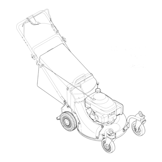
Operator's Manual
21" Self-Propelled
Mower
Model 986
IMPORTANT:
Read safety rules and instructions
carefully
Warning:
This unit is equipped with an internal combustion engine and should not be used on or near any unimproved forest-covered,
brush-covered
or grass-covered
land unless the engine's exhaust system is equipped with a spark arrester meeting applicable local or state
laws (if any), If a spark arrester is used, it should be maintained
in effective working order by the operator, In the State of California
the
above is required by law (Section 4442 of the California Public Resources
Code), Other states may have similar laws, Federal laws apply
on federal lands, A spark arrester for the muffler is available through your local dealer or contact the service department,
P,O, Box 361131
Cleveland, Ohio 44136-0019,
MTD LLC.,P.O. Box361131,Cleveland,Ohio 44136-0019
PRINTED IN U.S.A.
Form No.769-01642
(3/2005)
Advertisement
Table of Contents

Related Manuals for MTD 12A-986Q795


Summary of Contents for MTD 12A-986Q795
- Page 1 Code), Other states may have similar laws, Federal laws apply on federal lands, A spark arrester for the muffler is available through your local dealer or contact the service department, P,O, Box 361131 Cleveland, Ohio 44136-0019, MTD LLC.,P.O. Box361131,Cleveland,Ohio 44136-0019 PRINTED IN U.S.A. Form No.769-01642 (3/2005)
- Page 2 You can locate the model plate by standing at the operating position and looking down at the rear of the deck. This information will be necessary to use the manufacturer's web site and/or help from the Customer Support Department or an authorized MTD Products dealer.
- Page 3 SECTION 1: IMPORTANT SAFEOPERATION P RACTICES WARNING: This symbol points out important safety instructions which, if not followed, could endanger the personal safety and/or property of yourself and others. Read and follow all instructions in this manual before attempting to operate this machine. Failure to comply with these instructions may result in personal injury.
- Page 4 Children 16. Mowindaylight o r good artificial l ight; w alk, n otrun. 17. Stop thebladewhen crossing gravel d rives, Tragic accidents can occur if the operator is not alert to walkways o rroads. the presence of children. Children are often attracted to 18.
- Page 5 11. Replace gasoline c apandtighten securely. Keep all nuts, bolts, and screws tight to be sure the 12. If gasoline isspilled, w ipeitofftheengine and equipment is in safe working condition. equipment. Moveunit t oanother a rea. W ait5 Never tamper with safety devices. Check their minutes b efore starting theengine.
- Page 6 SIGHT AND HOLD THIS LEVEL WITH A VERTICAL TREE i,II A POWER POLE A CORNER OFA BUILDING >, OR A FENCE POST >, >, 15 ° WARNING Do not mow on inclines with a slope in excess of 15 degrees (a rise of approximately 2-1/2 feet every 10 feet).
- Page 7 SECTION 3: ASSEMBLING YOUR LAWNMOWER Removing UnitFromCarton SettingUpYourLawnMower • Remove staples, break glue on top flaps, or cut AssemblingHandle tape at carton end and peel along top flap to open • Lift up and pull back on the upper handle to raise carton.
- Page 8 Fasten the cable to the lower handle with the two cable ties found on the lower handle. Pull the cable Grass Bag Adapter ties tight and trim off the excess. See Figure 5. Cable Tie Lower Handle Nuts Figure 5 Figure 7 Attaching S tarterRope •...
- Page 9 SECTION 4: KNOW YOUR LAWNMOWER Drive Clutch Control Height Adjustment Control Handle Lever Grass Catcher Recoil Trail Shield Side-Discharge ....... Chute Mulching Plui Figure 10 Read this operator's manual and safety rules before CuttingHeightAdjustmentLever operating your lawn mower. Compare the illustration in The cutting height adjustment lever is located above Figure 10 with your lawn mower to familiarize yourself the left rear wheel.
- Page 10 SECTION 5: OPERATING Y OUR LAWNMOWER WARNING: Be sure no one other than the ARNING" operator is standing near the lawn mower while Read, understand, and follow all instructions and warnings on the machine and starting engine or operating mower. in this manual before operating.
- Page 11 Using Your LawnMower For effective mulching, do not cut wet grass. New or thick grass may require a narrower cut. If the grass has grown in excess of 4", mulching is not recommended. Mow using the side discharge to reduce the grass ARNING"...
- Page 12 DriveClutchControl CasterLockAdjustment The casters can be locked in a straight ahead position The adjustment wheel is located in the drive clutch or position to swivel freely. See Figure 13. control handle housing and is used to tighten or loosen the drive belt. You will have to adjust the drive clutch •...
- Page 13 SECTION 7: MAINTAINING YOUR LAWNMOWER Inspect muffler periodically, and replace if necessary. Damaged mufflers or spark arresters can create a fire hazard. Make sure to avoid muffler ARNING" Always stop the engine and disconnect the spark plug wire before performing any maintenance work or and surrounding areas while the mower engine is adjustments on your lawn mower.
- Page 14 SECTION 8: SERVICING YOUR LAWNMOWER • Place the blade on the adapter. Be certain the WARNING: Always stop the engine and blade is aligned and seated on the blade adapter disconnect the spark plug wire before flanges. performing any maintenance work or •...
- Page 15 • Remove the hex bolt from the rear of unit holding • Slide the belt out from between the belt keeper the transmission to the mower housing. bracket and the idler pulley. See Figure 19. See Figure 18. • Place the new belt over the transmission pulley. Start the belt in the pulley groove and rotate the pulley until the belt is seated in transmission pulley.
- Page 16 SECTION 10: TROUBLESHOOTING Problem Cause Remedy Engine fails to start Blade control handle disengaged. Engage blade control handle. Spark plug wire disconnected. Connect wire to spark plug. Fuel tank empty or stale fuel. Fill tank with clean, fresh gasoline. Choke lever not in the "On" position Place choke lever to the "On"...
- Page 17 NOTES...
- Page 18 SECTION 11: PARTS LISTFORMODEL 986 IMPORTANT: proper working machine, use Factory Approved Parts. V-BELTS are specially designed to engage disengage safely. A substitute (non OEM) V-Belt be dangerous disengaging completely.
- Page 19 Model986 PartNo. Ref. Pa_ No. Ref. Description Description Control Handle 756-04161 647-0004 Half Pulley: Upper 25mm x 2.62 736-0250 Flat Washer 1.00 x 1.75 x .107 731-1057 Upper Control Housing Control Lever 736-04173 731-0620 Spring Washer 1.005 x 1.825x .048 748-04082 731-1058 Lower Control Housing...
- Page 20 Model986...
- Page 21 Model986 Ref. Ref. Part No. Part No. Part Description Part Description 731-1901A Trail Shield 714-0474 Cotter Pin 732-0842 Trail Shield Wire 682-3053 Handle Bracket Assembly - LH 736-0264 Flat Washer.330 ID x.630 OD 682-3052 Handle Bracket Assembly - RH 714-0104 Cotter Pin 725-0157 Cable Tie...
- Page 22 NOTES...
- Page 23 NOTES...
- Page 24 MANUFACTURER'S LIMITED WARRANTY FOR: rized service dealer. The limited warranty set forth below is given by MTD LLC with respect to new merchandise purchased and used in the United MTD does not extend any warranty for products sold States, its possessions and territories.
Need help?
Do you have a question about the 12A-986Q795 and is the answer not in the manual?
Questions and answers