Advertisement
Quick Links
Safety • Assembly • Operation • Tips & Techniques • Maintenance • Troubleshooting • Parts Lists • Warranty
OPERATOR'S MANUAL
21" Self-Propelled Mower — Model Series 989
IMPORTANT
READ SAFETY RULES AND INSTRUCTIONS CAREFULLY BEFORE OPERATION
Warning: This unit is equipped with an internal combustion engine and should not be used on or near any unimproved forest-covered, brush-
covered or grass-covered land unless the engine's exhaust system is equipped with a spark arrester meeting applicable local or state laws (if any).
If a spark arrester is used, it should be maintained in effective working order by the operator. In the State of California the above is required by law
(Section 4442 of the California Public Resources Code). Other states may have similar laws. Federal laws apply on federal lands. A spark arrester
for the muffler is available through your nearest engine authorized service dealer or contact the service department, P.O. Box 361131 Cleveland,
Ohio 44136-0019.
FORM NO. 770-02331
PRINTED IN U.S.A.
MTD LLC, P.O. BOX 361131 CLEVELAND, OHIO 44136-0019
01/2006
Advertisement

Related Manuals for MTD Yard-Man 989 Series


Summary of Contents for MTD Yard-Man 989 Series
- Page 1 (Section 4442 of the California Public Resources Code). Other states may have similar laws. Federal laws apply on federal lands. A spark arrester for the muffler is available through your nearest engine authorized service dealer or contact the service department, P.O. Box 361131 Cleveland, Ohio 44136-0019. FORM NO. 770-02331 PRINTED IN U.S.A. MTD LLC, P.O. BOX 361131 CLEVELAND, OHIO 44136-0019 01/2006...
-
Page 2: Table Of Contents
You can locate the model plate by standing at the operating position and looking down at the rear of the deck . This information will be necessary to use the manufacturer’s web MTD LLC site and/or obtain assistance from the Customer Support P. O. BOX 361131 Department or an authorized service dealer. -
Page 3: Slope Gauge
Use this page as a guide to determine slopes where you may not operate safely. Do not operate your lawn mower on such slopes. Slope Gauge WARNING Do not mow on inclines with a slope in excess of 15 degrees (a rise of approximately 2-1/2 feet every 10 feet). -
Page 4: Safe Operation Practices
WARNING: Engine Exhaust, some of its constituents, and certain vehicle compo- nents contain or emit chemicals known to State of California to cause cancer and birth defects or other reproductive harm. DANGER: This machine was built to be operated according to the rules for safe operation in this manual. - Page 5 after the engine is shut off. Never place any part of the body accumulate in the area. in the blade area until you are sure the blade has stopped 9. Never remove gas cap or add fuel while engine is hot or rotating.
-
Page 6: Setup And Adjustment
1. Remove any packing material which may be between upper and lower handles. a. Pull up and back on upper handle as shown in Figure 3-1. Make certain the lower handle is seated securely into the handle mounting brackets. b. Tighten hand knobs to secure upper handle to Setup and lower handle. - Page 7 5. The mower was shipped with the mulching cover installed on the unit. For bagging purposes, you will need to attach the discharge chute and grass bag in place of the mulching baffle. a. Remove three wing nuts holding the mulching cover in place and remove the cover.
-
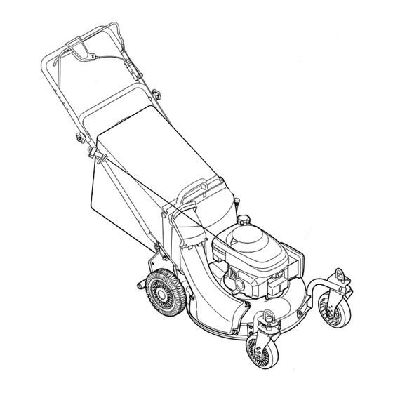
Page 8: Operating Your Lawn Mower
Know Your Lawn Mower Blade Control Drive Control Operating Height Adjustment Lever Your Lawn Mower Recoil Starter Gasoline Fill Side Discharge Chute WARNING Mulch Cover Discharge Chute The blade control is a Figure 4-1: The major components on the mower. safety device. - Page 9 WARNING: The operation of any lawn mower can result in foreign objects being thrown into the eyes, which can damage your eyes severely. Always wear safety glasses while operating or maintaining the mower. Starting Engine Operating WARNING: Be sure no one other than the op- erator is standing near the lawn mower while Your Lawn starting engine or operating mower.
-
Page 10: Maintaining Your Lawn Mower
Lubrication • Lubricate pivot points on the blade control at least once a season with light oil. The blade control must operate freely in both directions, Figure 5-1. Lubricate these • Lubricate the wheels at least once a season with points before light oil (or motor oil). - Page 11 Belt Care Blade Care When removing the cutting blade or when WARNING: When removing cutting blade sliding the belt around it, protect your hands for sharpening or replacement, protect your with a pair of heavy gloves. hands with a pair of heavy gloves or use a heavy rag to hold blade.
- Page 12 8. Loosen the belt keeper bolt and lock nut half a turn, Figure 5-6. 9. Using a pair of pliers, pull back and rotate belt keeper from the slot on the idler bracket, Figure 5-7. 10.Slide the belt out from between the belt keeper and the idler bracket.
- Page 13 Off-Season Storage The following steps should be taken to prepare your lawn mower for storage. • Clean and lubricate mower thoroughly as described in the lubrication instructions. Do not use a pressure washer or garden hose to clean your unit. Maintaining �...
-
Page 14: Trouble Shooting
Problem Remedy Cause Engine fails to start 1. Blade control disengaged. 1. Engage blade control. 2. Spark plug wire disconnected. 2. Connect wire to spark plug. 3. Fuel tank empty or stale fuel. 3. Fill tank with clean, fresh gasoline. 4. - Page 15 Safety Labels Found On Your Lawn Mower �� ������ ��� ���� �� ������� �� ��� ������� ������ ��������� ����� �� ����� ������� �� �� ��� ������ ������ �� �������� ������� ������������ Safety Labels WARNING DO NOT remove safety (or any) labels from •...
-
Page 17: Parts List
Ref. Part Description Ref. Part Description Number Number Parts List 747-0824 Control Lever 736-04173 Spring Washer 1.005 x 1.825 x .048 753-05096A Control Lever Assembly 748-04082 Blade Adapter Kit 746-0711B Drive Cable 51” 736-0524B Blade Bell Support 712-0324 Top Lock Nut 1/4-20 710-1257 Hex Bolt 3/8-24 x 2.5 746-0883... - Page 18 49 52...
- Page 19 Parts List Ref. Part Number Description Ref. Part Number Description 731-1901A Trail Shield 29 682-7528 Chain Cover Assembly 732-0842 Trail Shield Wire 30 741-0324A Flange Bearing .506 ID x .590 Lg 736-0264 Flat Washer.330 ID x.630 OD 31 682-7526 Transmission Axle Assembly 714-0104 Cotter Pin 32 618-0263A...
-
Page 20: Warranty
MANUFACTURER’S LIMITED WARRANTY FOR The limited warranty set forth below is given by MTD LLC with respect to outside of the United States, its possessions and territories, new merchandise purchased and used in the United States, its posses- except those sold through MTD’s authorized channels of export sions and territories.
Need help?
Do you have a question about the Yard-Man 989 Series and is the answer not in the manual?
Questions and answers