Table of Contents
Advertisement
Quick Links
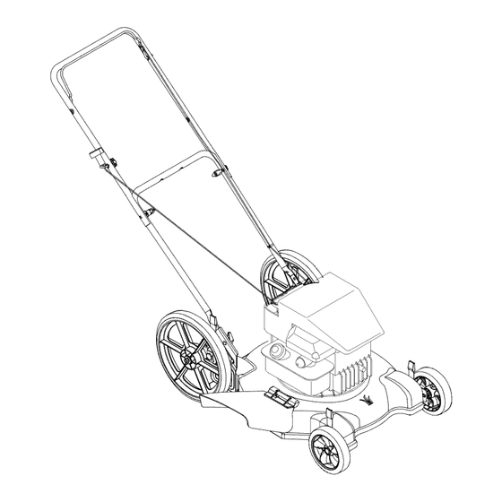
Operator's Manual
22" Rotary Mower
Model Series 050
IMPORTANT:
Read safety rules and instructions
carefully
before operating
equipment.
Warning:
This unit is equipped with an internal combustion engine and should not be used on or near any unimproved forest-
covered, brush-covered
or grass-covered
land unless the engine's exhaust system is equipped with a spark arrester meeting
applicable
local or state laws (if any). If a spark arrester is used, it should be maintained in effective working order by the operator.
In the State of California the above is required by law (Section 4442 of the California Public Resources Code). Other states may have
similar laws. Federal laws apply on federal lands. A spark arrester for the muffler is available through your nearest engine authorized
service dealer or contact the service department,
P.O. Box 361131 Cleveland, Ohio 44136-0019.
MTD LLC, P.O.BOX361131CLEVELAND,OHIO44136-0019
PRINTED IN U.S.A.
FORM NO. 769-00991
(11/2003)
Advertisement
Table of Contents

Related Manuals for MTD 11A-052A731


Summary of Contents for MTD 11A-052A731
- Page 1 Federal laws apply on federal lands. A spark arrester for the muffler is available through your nearest engine authorized service dealer or contact the service department, P.O. Box 361131 Cleveland, Ohio 44136-0019. MTD LLC, P.O.BOX361131CLEVELAND,OHIO44136-0019 FORM NO. 769-00991 PRINTED IN U.S.A.
-
Page 2: Customer Support
TABLEOFCONTENTS Content Page Content Page Customer Support Making Adjustments Important Safe Operation Practices Maintaining Your Lawn Mower Slope Gauge Troubleshooting Parts List Assembling Your Lawn Mower Operating Your Lawn Mower Warranty FINDINGMODELNUMBER This Operator's Manual is an important part of your new lawn mower. It will help you assemble, prepare and maintain the unit for best performance. -
Page 3: Section 1: Important Safeoperation P Ractices
SECTION 1: IMPORTANT SAFEOPERATION P RACTICES WARNING" This symbol points out important safety instructions which, if not followed, could endanger the personal safety and/or property of yourself and others. Read and follow all instructions in this manual before attempting to operate this machine. Failure to comply with these instructions may result in personal injury. - Page 4 Never fuel machine indoors because flammable vapors will accumulate in the area. Slopes are amajor factor related toslip and fall a ccidents which can Never remove gas cap or add fuel while the engine is hot or result insevere injury. Operation onslopes requires extra c aution.
- Page 5 SIGHT AND HOLD THIS LEVEL WITH A VERTICAL TREE A POWER POLE Iq I A CORNER OF A BUILDING >_ 15 ° WARNING Do not mow on inclines with a slope in excess of 15 degrees (a rise of approximately 2-1/2 feet every 10 feet). A riding mower could overturn and cause serious injury.
-
Page 6: Section 3: Assembling Your Lawnmower
SECTION 3: ASSEMBLING YOUR LAWNMOWER LooseParts Once the carton is opened, you will find several loose parts like the wheels, handles, and chute deflector. A hardware pack is also included in the carton. Make sure to remove all loose parts before discarding the carton. Follow instructions below to attach these loose parts to your mower safely and properly for best performance. - Page 7 Ila@i l Lows Ha iI® Lower Handle Lift the rear of the deck and place it on a block securely. Place the lower handle, with the pointed end face down, Nuts over the handle bracket assemblies and position each handle bracket assembly stud into the bottom hole in the lower handle.
- Page 8 Attaching"Z" Fitting Hold the cable end near the left side of the upper handle and hook the "Z" end of the brake cable into the blade control handle from the inside to outside. See Figure 7A. SecuringBrake Cable Lower WARNING: The cable must be routed properly to avoid contact with all sharp edges Handle...
-
Page 9: Section 4: Operating Y Our Lawnmower
SECTION 4: OPERATING Y OUR LAWNMOWER g owyo law Now that you have set up your lawn mower for Blade Control Handle operation, get acquainted with its controls and features. These are described below and illustrated in Figure 11. This knowledge will allow Upper Handle you to use your new equipment to its fullest potential. - Page 10 ARNING: Be sure no one other than the operator is standing near the lawn mower while starting engine or operating mower. Never run engine indoors or in enclosed, poorly ventilated areas. Engine exhaust contains carbon monoxide, an odorless and deadly gas. Keep hands, feet, hair and loose clothing away from any moving parts on engine and lawn mower.
-
Page 11: Section 5: Making Adjustments
SECTION 5: MAKING ADJUSTMENTS ARNING: adjustments. Always stop engine, disconnect spark plug, and ground against engine before performing 8 Ii £ Hei£1t Height Adjustment Each wheel has a height adjustment lever to change the cutting height of the mower. Depress the lever towards the wheel and slide the lever assembly to desired position for a change in cutting height. -
Page 12: Section 6: Maintaining Your Lawnmower
SECTION 6: MAINTAINING YOUR LAWNMOWER 88s® alSe88mmssdatis s • Always observe safety rules when performing any maintenance. • The warranty on this lawn mower does not cover items that have been subjected to operator abuse or negligence. To receive full value from the warranty, operator must maintain the lawn mower as instructed here. •... - Page 13 Blade8a e ARNING: When removing the cutting blade for sharpening or replacement, protect your hands with a pair of heavy gloves or use a heavy rag to hold the blade. Periodically inspect the blade adapter for cracks, especially if you strike a foreign object. Replace when necessary.
-
Page 14: Section 7: Troubleshooting
SECTION 7: TROUBLESHOOTING Engine fails to start Blade control handle disengaged. Engage blade control handle. Spark plug wire disconnected. Connect wire to spark plug. Fuel tank empty or stale fuel. Fill tank with clean, fresh gasoline. Blocked fuel line. Clean fuel line. Faulty spark plug. - Page 15 NOTES...
- Page 16 SECTION 8: PARTS LISTFORSERIES 050...
- Page 17 Series050 Ref. Ref. Part No. Part Description Part No. Part Description 747-1161A Blade Control Handle 736-0741 Bell Washer.760 ID x 1.25 OD 687-02080 749-1092A Rear Pivot Arm Assembly - RH Upper Handle 687-02079 720-0279 Rear Pivot Arm Assembly - LH Wing Nut 734-04082 Rear Wheel 12 x 1.8...
- Page 18 NOTES...
- Page 19 NOTES...
- Page 20 MANUFACTURER'S LIMITED WARRANTY FOR: The limited warranty set forth below is given by MTD LLC with MTD does not extend any warranty for products sold or respect to new merchandise purchased and used in the exported outside of the United States, its possessions United States, its possessions and territories.
Need help?
Do you have a question about the 11A-052A731 and is the answer not in the manual?
Questions and answers