MTD 54M Operator's Manual
Push mower
Hide thumbs
Also See for 54M:
- Operator's manual (61 pages) ,
- Operator's manual (28 pages) ,
- Operator's manual (48 pages)
Table of Contents
Advertisement
Available languages
Available languages
Safe Operation Practices • Set-Up • Operation • Maintenance • Service • Troubleshooting • Warranty
O
'
M
peratOr
s
anual
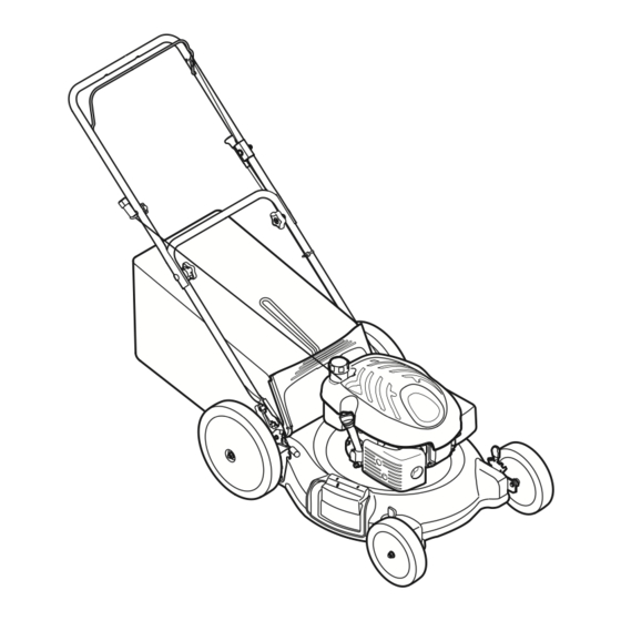
Push Mower — Model 54M
WARNING
READ AND FOLLOW ALL SAFETY RULES AND INSTRUCTIONS IN THIS MANUAL
BEFORE ATTEMPTING TO OPERATE THIS MACHINE.
FAILURE TO COMPLY WITH THESE INSTRUCTIONS MAY RESULT IN PERSONAL INJURY.
MTD LLC, P.O. BOX 361131 CLEVELAND, OHIO 44136-0019
Printed In USA
Form No. 769-03430
(September 6, 2007)
Advertisement
Table of Contents

Subscribe to Our Youtube Channel
Related Manuals for MTD 54M


Summary of Contents for MTD 54M
- Page 1 READ AND FOLLOW ALL SAFETY RULES AND INSTRUCTIONS IN THIS MANUAL BEFORE ATTEMPTING TO OPERATE THIS MACHINE. FAILURE TO COMPLY WITH THESE INSTRUCTIONS MAY RESULT IN PERSONAL INJURY. MTD LLC, P.O. BOX 361131 CLEVELAND, OHIO 44136-0019 Printed In USA Form No. 769-03430...
-
Page 2: Table Of Contents
Choose from the options below: ◊ Visit us on the web at www.mtdproducts.com ◊ Call a Customer Support Representative at (800) 800-7310 or (330) 220-4683 ◊ Write us at MTD LLC • P.O. Box 361131 • Cleveland, OH • 44136-0019... -
Page 3: Safe Operation Practices
Important Safe Operation Practices WARNING: This symbol points out important safety instructions which, if not followed, could endanger the personal safety and/or property of yourself and others. Read and follow all instructions in this manual before attempting to operate this machine. Failure to comply with these instructions may result in personal injury. - Page 4 A missing or damaged discharge cover can cause blade When starting engine, pull cord slowly until resistance contact or thrown object injuries. is felt, then pull rapidly. Rapid retraction of starter cord (kickback) will pull hand and arm toward engine faster than Many injuries occur as a result of the mower being pulled you can let go.
- Page 5 Service Check the blade and engine mounting bolts at frequent intervals for proper tightness. Also, visually inspect blade Safe Handling Of Gasoline: for damage (e.g., bent, cracked, worn) Replace blade with the original equipment manufacture’s (O.E.M.) blade only, To avoid personal injury or property damage use extreme listed in this manual.
-
Page 6: Spark Arrestor
Spark Arrestor Average Useful Life WARNING: According to the Consumer Products Safety Commission This machine is equipped with an (CPSC) and the U.S. Environmental Protection Agency (EPA), internal combustion engine and should not be used this product has an Average Useful Life of seven (7) years, or 140 on or near any unimproved forest-covered, brush hours of operation. - Page 7 2 — i ectiOn MpOrtant peratiOn ractices...
-
Page 8: Assembly & Set-Up
Assembly & Set-Up Contents of Carton • One Lawn Mower • One Lawn Mower Operator’s Manual • One Bottle of Oil • One Grass Catcher • One Hardware Pack • One Side Discharge Chute Assembly Locate the hairpin clip on the weld pin on each side of lower handle. - Page 9 The rope guide is attached to the right side of the upper Place rear of the mower deck on raised blocks. handle. See Fig. 3-3. Loosen the wing nut which secures the Remove lock nut from pivot arm assembly (on select rope guide.
- Page 10 Follow the steps below to attach the grass catcher: Slide two hooks of side discharge chute under hinge pin on mulching plug assembly. Lower the mulching plug. Do not Lift rear discharge door. See Fig. 3-6. remove side mulching plug at any time, even when you are not mulching.
-
Page 11: Controls & Features
Controls and Features Blade Control Choke Control Recoil Starter Grass Catcher Side Discharge Chute Mulch Plug Cutting Height Adjustment Levers Figure 4-1 Grass Catcher Blade Control The grass catcher, located at the rear of the mower, is used to bag The blade control is attached to the upper handle of the mower. -
Page 12: Operation
Operation Starting Engine WARNING: Be sure no one other than the operator is standing near the lawn mower while starting engine or operating mower. Never run engine indoors or in enclosed, poorly ventilated areas. Engine exhaust contains carbon monoxide, an odorless and deadly gas. -
Page 13: Maintenance & Adjustment
Maintenance & Adjustments Maintenance Lubricate the wheels at least once a season with light oil (or motor oil). If wheels are removed for any reason, lubricate General Recommendations surface of the pivot arm and inner surface of the wheel with light oil. See Fig. 6-1. •... - Page 14 Replacing Rear Flap Engine Care NOTE: Refer to the engine operation and maintenance sections To remove rear flap, lift rear door, and press flap in on in this manual for detailed instructions. either side to remove from hole. See Fig. 6-2. •...
-
Page 15: Service
Service Blade Care WARNING: An unbalanced blade will cause excessive vibration when rotating at high speeds. It WARNING: When removing the cutting blade for may cause damage to mower and could break sharpening or replacement, protect your hands with causing personal injury. a pair of heavy gloves or use a heavy rag to hold the Lubricate the engine crankshaft and the inner surface of blade. -
Page 16: Troubleshooting
Troubleshooting Problem Cause Remedy Engine Fails to start Blade control disengaged. Engage blade control. Spark plug boot disconnected. Connect wire to spark boot. Fuel tank empty or stale fuel. Fill tank with clean, fresh gasoline. Engine not primed (if equipped with primer). Prime engine as instructed in the Operation section. -
Page 17: Engine Operation
Engine Operation Fuel Cap Air Cleaner Starter Grip Oil Fill Oil Drain Spark Plug Figure 10-1 Pre-Operation Check Oil Recommendations NOTE: This engine is shipped without gasoline or oil in the engine. Running the engine with insufficient oil can cause serious engine damage and void the engine warranty. -
Page 18: Starting The Engine
Check Oil Level Check Fuel Level NOTE: Be sure to check the engine on a level surface with the Clean around fuel fill before removing cap to fuel. engine stopped. Fill tank to approximately 1-inch below lowest portion of Remove the oil filler cap and wipe the dipstick clean. See neck to allow for fuel expansion. -
Page 19: Engine Maintenance
Engine Maintenance WARNING: Periodic inspection and adjustment of the engine is essential Shut off the engine before performing if high level performance is to be maintained. Regular any maintenance. To prevent accidental start-up, maintenance will also ensure a long service life. The required disconnect the spark plug boot. - Page 20 Oil Service Air Cleaner Service • Check oil level regularly. Paper filters cannot be cleaned and must be replaced once a year or every 100 operating hours; more often if used in extremely • Be sure correct oil level is maintained. Check every five dusty conditions.
- Page 21 Spark Plug Service Measure the plug gap with a feeler gauge. Correct as necessary by bending side electrode. See Fig. 10-4. The gap should be set to 0.030 in. WARNING: DO NOT check for spark with spark plug removed. DO NOT crank engine with spark plug removed.
-
Page 22: Removing From Storage
Fuel Filter Service Storage The fuel filter cannot be cleaned and must be replaced once a Engines stored between 30 and 90 days need to be treated with year or every 100 operating hours; more often if run with old a gasoline stabilizer and engines stored over 90 days need to be gasoline. - Page 23 Notes...
-
Page 24: Illustrated Parts List
Model 54M... - Page 25 Model 54M Part Number Description Part Number Description 747-1161A Blade Control 738-04266 Shoulder Scr., .5D x .385 - RH Rear 749-1092A Upper Handle 732-0404 Front Spring Lever 720-0426 Height Adjust Knob 746-04299 Control Cable 710-0599 TT Screw, 1/4-20 x .500 726-0240 Cable Tie 736-0270...
- Page 26 Engine Model - 1P65...
- Page 27 Engine Model - 1P65 Part Number Description 951-10337 Fuel Tank 951-10336 Flywheel Shroud 951-10335 Rubber Fuel Tank Mounting Washer 951-10334 Oil Filler Tube Assembly 951-10333 Dipstick Assembly 951-10406 Cylinder Head Complete 951-10407 Short Block Assembly 951-10320 Stop Switch and Brake Assembly 951-10319 Recoil Spring and Pulley Assembly 951-10314...
-
Page 28: Emission Control System Warranty Statement
Elsewhere in the United States, new non-road, spark-ignition engines certified for model 2005 and later, must meet similar standards set forth by the U. S. EPA. MTD must warranty the emission control system on your engine for the period of time listed below, provided there has been no abuse, neglect or improper maintenance of your small off-road engine. - Page 29 (c) MTD will include a copy of the following emission warranty parts list with each new engine, using those portions of the list applicable to the engine.
-
Page 30: Warranty
MANUFACTURER’S LIMITED WARRANTY FOR The limited warranty set forth below is given by MTD LLC with c. Service completed by someone other than an authorized service respect to new merchandise purchased and used in the United States dealer. and/or its territories and possessions, and by MTD Products Limited d. -
Page 31: Spanish
LEA Y SIGA TODAS LAS INSTRUCCIONES DE ESTE MANUAL ANTES DE PONER EN FUNCIONAMIENTO ESTA MÁQUINA. SI NO RESPETA ESTAS INSTRUCCIONES PUEDE PROVOCAR LESIONES PERSONALES. MTD LLC, P.O. BOX 361131 CLEVELAND, OHIO 44136-0019 Impreso en Estados Unidos de América Formulario No. 769-03430... - Page 32 Elija entre las opciones que se presentan a continuación: ◊ Visite nuestro sitio web en www.mtdproducts.com ◊ Llame a un representante de Asistencia al Cliente al (800) 800-7310 ó (330) 220-4683 ◊ Escríbanos a MTD LLC • P.O. Box 361131 • Cleveland, OH • 44136-0019...
- Page 33 Medidas importantes de seguridad ADVERTENCIA: La presencia de este símbolo indica que se trata de instrucciones importantes de seguridad que se deben respetar para evitar poner en peligro su seguridad personal y/o material y la de otras personas. Lea y siga todas las instrucciones de este manual antes de poner en funcionamiento esta máquina.
- Page 34 No ponga las manos o los pies cerca de las piezas rotatorias control de la cuchilla y otros dispositivos de seguridad o en la tolva de la cortadora. El contacto con las cuchillas y protección en su lugar y funcionando. Nunca opere la puede producir la amputación de manos y pies.
- Page 35 Mantenga a los niños fuera del área de trabajo y bajo Limpie la gasolina derramada sobre el motor y el equipo. estricta vigilancia de un adulto responsable además del Traslade la máquina a otra zona. Espere 5 minutos antes de operador.
- Page 36 Guardachispas manual. “La utilización de partes que no cumplan con las especificaciones de equipos originales podría tener como ADVERTENCIA:ESTA resultado un rendimiento incorrecto y además la seguridad máquina está equipada con podría estar comprometida” un motor de combustión interna y no debe ser utilizada en o cerca de un terreno agreste cubierto No cambie la configuración del regulador del motor ni por bosque, malezas o hierba excepto si el sistema...
- Page 37 2 — M ectiOn edidas iMpOrtantes de seguridad...
- Page 38 Montaje y Configuración Contenido de la caja • Una Podadora • Uno Colector de Césped • Uno Botella del Aceite • Uno Manual de Operador • Uno Paquete de Hardware • Uno Canal de Descarga Lateral Montaje Localice el pasador de horquilla que se encuentra en el pasador soldado a cada lado de la manija inferior.
- Page 39 La guía de la cuerda está unida al costado derecho de la El reverso de lugar del cortacésped adorna en bloques manija superior. Afloje la tuerca de mariposa que sujeta la levantados. guía de la cuerda, Fig. 3-3. Quite la tuerca de cerradura de la asamblea de brazo de pivote (en modelos escogidos, éstos pueden ser incluidos por separado en una bolsa de plástico).
- Page 40 Levante la puerta de descarga posterior, Fig. 3-6. En el costado de la podadora, levante el adaptador para abono. Deslice los dos ganchos del canal de descarga lateral debajo del pasador de bisagra sobre el montaje del adaptador para abono. Baje el adaptador para abono. No extraiga la clavija para abono lateral en cualquier momento, aún cuando no esté...
- Page 41 Controles Y Características Control de cuchilla Perilla de Estárter Arrancador de retroceso Colector de Césped Canal de Descarga Lateral Clavija para abono Palanca de ajuste de altura de corte (en cada rueda) Figura 4-1 Colector de Césped Control de Cuchilla El colector de césped, localizado en el reverso del cortacésped, El control de la cuchilla está...
- Page 42 Funcionamiento Encendido del Motor ADVERTENCIA: Asegúrese que ninguna persona aparte del operador permanezca cerca de la podadora mientras arranca el motor u opera la misma. Nunca encienda un motor en espacios cerrados o en una zona con poca ventilación. El escape del motor contiene monóxido de carbono, un gas inodoro y letal.
- Page 43 Mantenimiento Y Ajustes Mantenimiento Lubrique el resorte de torsión y el punto de pivote de la puerta trasera de descarga y clavija de abono lateral Recomendaciones Generales periódicamente con aceite ligero para prevenir la oxidación, Fig. 6-1. • Respete siempre las reglas de seguridad cuando realice Siga la sección de Mantenimiento de Motor para lista de tareas de mantenimiento.
- Page 44 Reemplazo de alerón trasero Para quitar la tapa trasera, levante la puerta trasera, y la tapa de prensa en a ambos lados para quitar del agujero. Ver la Fig. 6-2. Quite la tapa del agujero de enfrente y sustituya por la nueva tapa en la orden de enfrente y la manera del retiro.
- Page 45 Servicio Cuidado de la Cuchilla Lubrique el cigüeñal del motor y la superficie interna del adaptador de la cuchilla con aceite ligero. Deslice el ADVERTENCIA: adaptador de la cuchilla sobre el cigüeñal del motor. Instale Cuando saque la cuchilla de corte para afilarla o reemplazarla, protéjase las manos la cuchilla con el lado marcado “Bottom”...
- Page 46 Solución de problemas Problema Causa Remedio El motor no arranca El control de lámina se retiró. Contratar el control de lámina. Alambre de bujía desconectado. Unir el alambre a la bujía. Depósito de combustible combustible vacío Llenar el tanque de la gasolina limpia, fresca. o añejo.
- Page 47 Problema Causa Remedio Demasiada vibración Cuchilla floja o desequilibrada. Apriete la cuchilla y el adaptador. Equilibre la cuchilla. Cuchilla abollada. Consulte a un distribuidor autorizado. La podadora no abona Césped húmedo. No corte el césped cuando está mojado, el césped espere hasta que sea más tarde para hacerlo.
- Page 48 Funcionamiento de Motor Tapón de combustible Depurador de aire Empuñadura del arranque Tapón de llenado de aceite Tubo de drenaje Bujía de encendido Silenciador Figura 10-1 Control Previo al Funcionamiento Recomendaciones Sobre el Aceite IMPORTANTE: Este motor se despacha sin gasolina ni aceite en el motor.
- Page 49 Verifique el Nivel de Combustible Antes de sacar la tapa para cargar combustible, limpie alrededor. Llene el tanque hasta aproximadamente 1 pulgada debajo de la parte más baja del cuello para permitir la expansión del combustible. Tenga cuidado de no llenar en exceso. Tapón de llenado IMPORTANTE: Antes de cargar, deje que el motor se enfríe /varilla del nivel...
- Page 50 Mantenimiento de Motor La inspección y los ajustes periódicos del motor son esenciales ADVERTENCIA: Apague el motor antes de realizar si se desea mantener un alto nivel de desempeño. El el mantenimiento. Para evitar una puesta en marcha mantenimiento regular también garantizará una prolongada accidental, desconecte la funda de la bujía.
- Page 51 Mantenimiento del aceite NOTA: Elimine el aceite del motor usado de la manera que sea compatible con el medio ambiente. Sugerimos que lo • Inspeccione el nivel de aceite regularmente. coloque en un recipiente sellado y lo lleve a la estación de servicio local para su recuperación.
- Page 52 Mantenimiento de Bujía Mida la separación de bujía con un calibrador. Corrija de ser necesario torciendo el electrodo lateral. Vea la fig. 10-4. ADVERTENCIA: NO pruebe la chispasi no está la La separación debe establecerse en 0,030 pulg. bujía de encendido. NO de arranque al motor si no está...
- Page 53 Servicio con Filtro de Combustible Almacenamiento El filtro de combustible no puede ser limpiado y debe ser Los motores almacenados entre 30 y 90 días tienen que sustituido una vez al año o cada 100 horas de operaciones; más a ser tratados con un estabilizador de gasolina y los motores menudo de ser dirigido con vieja gasolina.
- Page 54 California y en otra parte en la Cobertura de Garantía de Defectos de Control de Emisión de los Estados Unidos El Bordo de Recursos de Aire de California (CARB), la U. S. EPA y MTD se complacen en explicar la garantía del sistema de control de emisiones de su motor para equipo todo terreno, modelo, año 2005 y versiones posteriores.
- Page 55 (c) MTD incluirá una copia de la siguiente lista de piezas bajo garantía contra emisiones con cada nuevo motor, utilizando las partes de la lista aplicables al motor.
- Page 56 El daño resultante por la instalación o el personas o personas jurídicas, incluidos los distribuidores o uso de piezas, accesorios o uniones no aprobados por MTD para su los minoristas con respecto a los productos, obligará a MTD.
Need help?
Do you have a question about the 54M and is the answer not in the manual?
Questions and answers