Table of Contents
Advertisement
Operator's
Manual
CRRFTSMRH
26" SNOW THROWER
Model No. 247.889703
CAUTION:
Before
using
this product,
read this
manual
and follow
all
safety
rules
and operating
instructions.
o SAFETY
ASSEMBLY
OPERATION
MAINTENANCE
PARTS LIST
o ESPANOL
Sears Brands Management
Corporation,
Hoffman Estates, IL 60179, U.S.A.
Visit our website:
www.craftsman.com
FORMNO.769-05136E
7/26/2011
Advertisement
Table of Contents

Related Manuals for Craftsman 247.889703


Summary of Contents for Craftsman 247.889703
- Page 1 Model No. 247.889703 o SAFETY ASSEMBLY OPERATION MAINTENANCE PARTS LIST CAUTION: Before using o ESPANOL this product, read this manual and follow safety rules and operating instructions. Sears Brands Management Corporation, Hoffman Estates, IL 60179, U.S.A. Visit our website: www.craftsman.com FORMNO.769-05136E 7/26/2011...
- Page 2 This warranty isvoid ifthis product isever used w hile providing commercial services orifrented toanother person. w arrantycoverage details to obtain repairor replacement, v isit the website: www.craftsman.com This warranty covers ONLYdefects in material and workmanship. Warranty coverage does NOT include: •...
- Page 3 This machinewas builtto be operatedaccordingto the safeopera- This symbolpointsout importantsafetyinstructionswhich,if not tion practicesin this manual.As with anytype of powerequipment, followed,couldendangerthepersonalsafetyand/orpropertyof carelessnessor error on the partof the operatorcan resultin serious yourselfand others. Readand followall instructionsin this manual injury.This machineis capableof amputatingfingers,hands,toes beforeattemptingto operatethis machine.Failureto complywith and feet and throwingdebris.Failureto observethe followingsafety these instructionsmay resultin personalinjury.Whenyou seethis...
- Page 4 Safe Handling of Gasoline • Exerciseextremecautionwhenoperatingon or crossinggravel surfaces.Stay alertfor hidden hazardsor traffic. Toavoidpersonalinjuryor propertydamageuseextremecare in handlinggasoline.Gasolineis extremelyflammableand the vaporsare • Exercisecautionwhenchangingdirectionand whileoperatingon explosive.Seriouspersonalinjurycan occurwhengasolineis spilled slopes.Do notoperateon steep slopes. on yourselfor yourclotheswhichcan ignite.Washyour skin and • Planyoursnow-throwing patternto avoiddischargetowards changeclothesimmediately.
- Page 5 MAINTENANCE & STORAGE DO NOT MODIFY ENGINE • Nevertamperwith safetydevices.Checktheirproperoperation Toavoidseriousinjuryor death,do not modifyengine in any way. regularly.Referto the maintenance and adjustmentsectionsof Tampering with the governorsettingcanlead to a runawayengineand this manual. cause it to operateat unsafespeeds.Nevertamperwithfactory setting of engine governor. •...
- Page 6 SAFETY SYMBOLS This pagedepictsand describessafetysymbolsthat mayappear on this product. Read,understand,and followall instructionson the machine beforeattemptingto assembleand operate. READ THE OPERATOR'S MANUAL(S) Read, understand, and follow all instructions in the manual(s) before attempting to assemble operate WARNING-- ROTATING BLADES Keep hands out of inlet and discharge openings while machine is running.
- Page 7 Thispage leftintentionally blank.
- Page 8 NOTE:References to rightor left sideof the snowthrowerare determined from behindthe unit in the operatingposition(standing directlybehindthe snow thrower,facingthe handlepanel). Chute Control Head REMOVING FROM CARTON _ort Cut the cornersof thecarton and lay the sidesflat on the ground. Bracket Removeand discard all packinginserts. Movethe snowthrowerout of thecarton.
- Page 9 Placechuteontochute baseand ensurechutecontrol rod is Chute Controlf positionedunder handlepanel.Installhex boltpreviouslyremoved but do notsecurewith wing nutat this time.See Figure4. Squeezethetriggeron the handlepaneljoystickand rotatethe chute byhand to face forward.The holesin the chutecontrol inputwill be facing up. See Figure5. NOTE:The chutewill not rotatewithoutsqueezing the triggeron the joystick.
- Page 10 Makesureall cablesare routedto the left of the chute control rod.Line up the hole in the rod with thearrowon the inputshaft /i _ and insertthe rod into the inputshaftbelowjoystickon handle panel.See Figure7. NOTE:The chutecontrol rodwill fit snugglyintothe inputshaft. Supportthe rearof the dashpanel withone handwhile insertingthe rod with yourother handto ensurethe rod isinserted allthe wey into the input shaft.
- Page 11 ,iiiiiii!,! ii_ili iiii 10. Checkthat all cables are properlyroutedthroughthecable guide on theengine.See Figure10. NOTE: if the chutecontrol is notassembledcorrectlyit will not move freelynor will it movefully to the rightand left. 11. Theextensioncord forthe electricstarteris fastenedwith a cabletie to the rearof the auger housingfor shippingpurposes. Cutthe cabletie and removecord beforeoperatingthe unit.
- Page 12 Chute Clean=Out Tool A chute clean-out tool is fastenedto the top of the augerhousing with a mountingclip. See Figure12.The tool is designedto cleara chuteassemblyof ice and snow.This item is fastenedwith a cabletie at the factory.Cut thecable tie beforeoperatingthe snowthrower. Chute Clean=out Tool loff ving parts h ave...
- Page 13 Auger Control Priorto operatingyoursnowthrower,carefullyread and followall instructionsbelow.Performall adjustments to verifyyoursnow throweris operatingsafelyand properly. Checktheadjustmentof the augercontrolas follows: Whentheauger controlis releasedand in the disengaged"up" position,the cableshouldhavevery little slack. It shouldNOTbe tight. In a well-ventilated area,start the snowthrowerengine.Refer to Startingthe Enginein the Operationsection.Makesurethe throttleis set in the FASTposition.
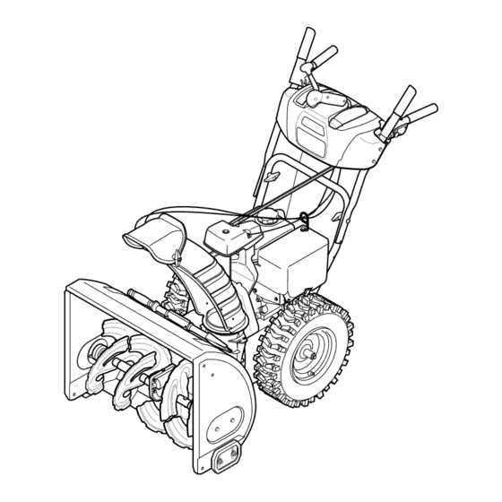
- Page 14 Shift Lever Drive Control / Four=Way Chute Control" (Joystick) Auger Control Gas Cap Chute Assembly Mumer Recoil Starter Handle Clean Out Tool Primer ___. FUEL LEVEL Throttle Control Choke Control Electric Starter Button Oil Drain Electric Starter Outlet Augers Skid Shoe Figure15 Nowthat youhaveset up yoursnowthrower,it's importantto become acquainted with its controlsand features.Referto Figure15.
- Page 15 THROTTLE CONTROL DRIVE CONTROL/AUGER CONTROL LOCK DRIVE CONTROL Thethrottlecontrolis locatedon the rearof the engine.It regulatesthe speedof theengine and will shutoff the enginewhenmovedintothe STOPposition. Depressingthe primerforcesfuel directlyinto the engine'scarburetorto aid in cold-weather The drivecontrolis locatedon the righthandle.Squeezethe control starting. grip againstthe handleto engagethe wheeldrive. Releaseto stop. The drivecontrolalso lockstheauger controlso youcan operate RECOIL STARTER...
- Page 16 CLEAN-OUT TOOL • Refuelin a well-ventilated area with the enginestopped.Do not smokeor allowflamesor sparksin the areawherethe engineis refueledor wheregasolineisstored. Neveruse yourhandsto cleara cloggedchute assembly.Shut • Donot overfillthe fueltank.After refueling,makesurethe tank off engineand remainbehindhandlesuntilall movingpartshave cap is closed properlyand securely. stoppedbeforeusingthe clean-outtoolto clear thechute assembly. •...
- Page 17 2. Move t hrottle control toFAST (rabbit) _ position. TO ENGAGE DRIVE I,"1 pos t /co d 3. Move c hoke tothe CHOKE engine start). If With the throttlecontrolin the Fast(rabbit) '_ position,move engineis warm,placechokein RUNposition. shiftleverintoone of thesix forward(F) positionsor two reverse Pushprimerthree (3) times, makingsureto covervent hole when (R) positions.Selecta speedappropriatefor the snowconditions pushing.If engine iswarm,push primeronlyonce.
- Page 18 MAINTENANCE SCHEDULE Beforeperforming anytypeof maintenance/service, disengage all Followthe maintenanceschedulegivenbelow.This chart describes controls and stoptheengine.Waituntilall moving partshavecometo serviceguidelinesonly. Usethe ServiceLog columnto keeptrackof a complete stop.Disconnect sparkplugwireandgrounditagainstthe completedmaintenance tasks.To locate the nearest Sears Service enginetoprevent u nintended starting. A lways wearsafety glassesduring Centeror to scheduleservice,simplycontactSears at 1-800-4-MY-HOME®.
- Page 19 Changing Engine Oil NOTE:Changethe engineoil after the first 5 hoursof operationand oncea seasonor every 50 hoursthereafter. Drainfuelfrom tank by runningengineuntilthe fuel tank is empty. Be surefuel fill cap is secure. Placesuitableoil collectioncontainerunderoil drain plug. Removeoil drain plug.See Figure18. Tip engineto drainoil intothe container.Usedoil mustbe disposedof at a propercollectioncenter.
- Page 20 Measurethe plug gap with a feelergauge.Correctas necessary by bendingsideelectrode.See Figure20. Thegap shouldbe set to .02-.03inches (0.60-0.80ram). Checkthat thespark plug washeris in good conditionand thread the sparkplug in by handto preventcross-threading. Afterthe sparkplug is seated,tightenwith a spark plugwrenchto compressthe washer. NOTE:Wheninstallinga newsparkplug,tighten 1/2-turnafter the spark plugseatsto compressthe washer.Whenreinstalling a used spark plug,tighten 1/8-to 1/4-turn after the sparkplug seatsto compressthe washer.
- Page 21 SHAVE PLATE AND SKiD SHOES Theshaveplateand skid shoeson the bottomof the snowthrowerare subjectto wear.They shouldbe checkedperiodicallyand replaced whennecessary. NOTE:Theskid shoes on this machinehavetwo wearedges.When one sidewearsout, theycan be rotated1800 to usethe otheredge. Toremoveskid shoes: Removethefour carriagebolts and hexflangenuts which secure them tothe snowthrower.
- Page 22 Chute Control Toachievemorechute control rodengagementin the inputshaft under the handlepanel,thechute controlrod will haveto be adjusted.Refer to Figure26. Toadjustthis rod,proceedas follows: Removethe cotter pin fromthe hole closestto the chutecontrol headon the chutecontrolinput. Pull out thechute controlrod until thehole in it linesup with the otherhole in thechute controlinput.
- Page 23 4. Carefully pivot the snow thrower upand forward so that i trests o n the auger housing. 5. Remove the frame c over from the underside ofthe snow thrower byremoving the self-tapping screws which s ecure it.See Figure 6. Remove the belt a sfollows. Refer toFigure 30. a.
- Page 24 Drive Belt To removeand replaceyoursnow thrower'sdrivebelt, proceedas follows: Topreventspillage,removeall fuel fromtank by runningengine until it stops. Removethe plasticbelt coveron the front of the engineby remov- ing the two self-tappingscrews.See Figure27 on previouspage. Removethe beltfrom enginepulleyas follows.Referto Figure32. Rollthe auger beltoff theengine pulley. Use a wrenchto pivotthe idler pulleytowardthe right.
- Page 25 Carefullyremovethe hexnut and washerwhich securesthehex shaftto the snowthrowerframeand lightlytap the shaft'send to dislodgethe ball bearingfrom the rightsideof the frame.See Figure35. NOTE:Be carefulnot to damagethe threadson the shaft. Carefullypositionthe hexshaftdownwardand to the left before carefullyslidingthe frictionwheelassemblyoff the shaft. See Figure36. NOTE: If you'rereplacingthe frictionwheelassemblyas a whole, discardthe wornpartand slidethe newpart ontothe hexshaft.
- Page 26 If the snowthrowerwillnot be usedfor30 daysor longer,or if it is the end of the snowseasonwhenthe last possibilityof snowis gone,the equipmentneedsto be storedproperly.Followstorageinstructionsbelowto ensuretop performance from the snowthrowerfor manymoreyears. PREPARING SNOW THROWER PREPARING ENGINE Whenstoringthe snowthrowerin an unventilatedor metal stor- Enginesstoredover30 days need to be drainedof fuel to prevent age shed,careshouldbe taken to rustprooftheequipment.Using deterioration and gumfrom formingin fuel systemor on essential a light oil or silicone,coat theequipment,especiallyanychains,...
- Page 27 Enginefails to start Chokecontrolnot in CHOKEposition. Movechokecontrolto CHOKEposition. Sparkplugwire disconnected. Connectwireto sparkplug. Faultysparkplug. Clean,adjustgap,or replace. Fueltank emptyor stalefuel. Filltank with clean,freshgasoline. Enginenot primed. Primeengineas instructedin the OperationSection. Keynot inserted. Insertkeyfully intothe switch. Connectone end of the extensioncordto the electric Extensioncordnot connected(when usingelectricstartbutton,on modelsso starteroutletand the otherend to a three-prong equipped).
- Page 28 Craftsman Snow Thrower Model 247.889703 _39_ - _' ',_ 1;f...
- Page 29 Craftsman Snow Thrower IViodel 247.889703 931-2643 Clean-OutTool 741-0663 FlangeBearing 710-0642 Screw,1/4-20x 0.75 712-04065 FlangeLockNut 756-04224 Fiat idler Pulley 790-00087A-0637 BearingHousing 710-0347 Hex Bolt,3/8-16x 1.75 721-0325 Plug 736-3084 Fiat Washer 790-00080A-0637 Augerldler Bracket 736-0174 WaveWasher 715-04021 DowelPin 938-0281 ShoulderScrew 684-04108-0637 SpiralAssembly-RH...
- Page 30 Craftsman Snow Thrower IViodel 247.889703 _'.'X 'J2_\ < ........,_!: ......¢o_ ....
- Page 31 Craftsman Snow Thrower Model 247.889703 684-04112B HandleEngagement A ssemblyRH 984-04338 4-WayChuteControl Assembly 749-04191A-0637 UpperHandleLH _ 738-04367 _ FlangeShoulderScrew 731-04894D Lock Plate 710-04326 Screw,#8-16x 0.50 684-04250 PivotRod 732-04219C ClutchLockSpring 935-0199A RubberBumper 712-3087 WingNut, 1/4-20 714-04040 BowTie CotterPin 710-3069 Screw,1/4-20x .500 731-04896B...
- Page 32 Craftsman Snow Thrower Model 247.889703 i,73/ <...
- Page 33 Craftsman Snow Thrower IViodel 247.889703 656-04055 DiscAssembly,FrictionWheel 735-04099 Plug,3/8 ID 710-0809 Hex Screw,1/4-20,1.25,Gr5 684-04153 FrictionWheelAssembly,5.50D 710-0191 Hex Screw,3/8-24, 1.25,Gr8 L684-04154B-0637_Supp°rt Bracket, F riction Wheel 684-04156A Shift Assembly,Rod 710-0672 Hex Screw,5/16-24,1.25,Gr5 710-0627 Hex Screw,5/16-24,.750,Gr5 710-0654A Screw,Seres,3/8-16,1.00 710-0788 Screw,1/4-20,1.000 710-1245B Hex Screw,5/16-24,.875,Gr8 710-1652 Screw,1/4-20x .625...
- Page 34 Craftsman Engine IViodel 270=SU=11 For Snow IViodel 247.889703 951-11282 MufflerAssembly 710-04911 StudM8x36 951-10657 MufflerStudAssembly 951-11285 ExhaustPipe Gasket 712-04214 Nut,M8 951-11111 ExhaustPipe Shield 710-04914 Bolt M6xl0 710-04915 Bolt M6x12 951-10642A MufflerShield...
- Page 35 Craftsman Engine Model 270=SU=11 For Snow Model 247.889703 951-11897 Carburetor GasketPlate 951-11112 ChokeControl 951-10634 EngineShroud 712-04213 951-11284 ChokeKnob 951-10757 ThrottleControlKnob 951-10637 IgnitionSwitchAssembly 731-05632 951-10640 Choke PushRod 951-10635 HeaterBox 710-04919 Bolt M6x25...
- Page 36 Craftsman Engine IViodel 270=SU=11 For Snow IViodel 247.889703...
- Page 37 Craftsman Engine IViodel 270=SU=11 For Snow IViodel 247.889703 951-12111 PistonRingSet 951-11283 Oil FillPlugAssembly 951-11632 PistonPin Snap Ring 951-11577 O-Ring15.8x2.5 951-12007 Piston 951-11368 Oil Seal,25x41.25x6 951-11633 PistonPin 951-11249 CrankcaseKit 710-04915 Bolt M6x12 (Incl.61,64,76,77,81) 951-11113 Air Shield 951-11350 Oil DrainPipe Assy. 951-11573...
- Page 38 Craftsman Engine IViodel 270=SU-11 For Snow IViodel 247.889703...
- Page 39 Craftsman Engine IViodel 270=SU=11 For Snow IViodel 247.889703 710-04744 Bolt M6x16 951-11054A ValveCover 731-07059 BreatherHose 726-04101 Hose Clamp 951-11565 ValveCoverGasket 951-12000 Retainer,In.Valve Spring 951-11892 RockerArmAssembly 751-11124 Nut, PivotLocking 751-11123 AdjustingNut ,Valve 951-11893 RockerArm 710-04902 Bolt, Pivot 951-12002 Adjuster,ExhValve 951-12003 Retainer,Ex.Valve Spring...
- Page 40 Craftsman Engine IViodel 270=SU=11 For Snow IViodel 247.889703...
- Page 41 Craftsman Engine IViodel 270=SU=11 For Snow IViodel 247.889703 710-04939 Stud M6x117 710-04910 Stud M6x105 951-11567 CarburetorInsulatorGasket 951-11896 CarburetorInsulator 951-11569A CarburetorGasket 951-10639A PrimerAssembly 951-11824 PrimerBulb 951-10638A Carburetor Assembly 951-11897 CarburetorGasketPlate ChokeShaft ChokePlate ThrottleShaft ThrottlePlate Screw M3x5 Lock Washer Gasket,ThrottlePlate IdleJet Assembly...
- Page 42 Craftsman Engine IViodel 270-SU-11 For Snow IViodel 247.889703. _130 94 _ _'91 94.4 _95 951-10646 IgnitionCoil Assembly 951-11110 Air FlowShield 710-04940 BoltM6xlO 710-04919 BoltM6x25 951-12416 Flywheel 951-10909 Fan,Cooling 951-10911 Pulley,Starter 712-04209 Nut,Special,M14x1.5 710-04915 BoltM6x12 951-10663A BlowerHousing 736-04455 Gasket6 710-04974 BoltM6xlO...
- Page 43 Craftsman Engine IViodel 270=SU=11 For Snow IViodel 247.889703. 951-10758 951-10662 ThrottleControlAssemlby Engine/ DipstickCover 710-04928 BoltM6x12 710-04905 Bolt 951-11108 710-04915 Bolt M6x12 GovernorSystemShield 951-11935 951-11381 GovernorSpring Oil FillTubeO-Ring 951-10664 951-11913 ThrottleLinkageSpring Oil FillTubeAssembly 951-10665 951-11904 ThrottleLinkage Dipstick O-Ring 951-11106 GovernorArm 951-12482...
- Page 44 Craftsman Engine Model 270=SU=11 For Snow Model 247.889703. 777S33610 777122991 777123026 777122990 777122992...
- Page 45 Craftsman Snow Thrower IViodel 247.889703 777S32636 777D16339 1001 lno-Nv:=lo 7VflNV_ S,HOIVU3dO QV3U 7; "S]OVJHflS 1]AVH9 NO 9NIIVH3dO N3HM NOIlflV9 V91X3 389 "$830NV18t8 IV ]98VHOSIO 103810 H]A]H '$31UflrNI $133r80 NMOUH1 QIOAV 01 "t' '3NIHOVVJ 9NI31^EG8 EIO 9NI99013Nn ]H0_38 O3dd01S 3AVH $1HVd ONIAO_ ]lV lllNfl S]3QNVH ONIH38 NIV_3U ONV '3NIgN] d018 '$U]A31 HOlfllO 39VgN]$10 "8...
- Page 46 MTD CONSUMER GROUP INC (MTD), the California Air Resources Board (CARB) and the United States Environment Protection Agency (U. S. EPA) Emission Control System Warranty Statement (Owner's Defect Warranty Rights and Obligations) EMISSION CONTROLSYSTEM COVERAGE IS APPLICABLE TOCERTIFIEDENGINESPURCHASED IN CALIFORNIA IN 2005 ANDTHERE- AFTER,WHICHARE USEDIN CALIFORNIA, A NDTO CERTIFIED MODELYEAR2005 AND LATERENGINESWHICHARE PURCHASED AND USEDELSEWHERE IN THE UNITEDSTATES.
- Page 47 (4)Repair orreplacement ofany warranted part under the warranty provisions ofthis article m ust beperformed atnocharge tothe owner ata warranty station. (5)Notwithstanding the provisions ofSubsection (4) above, warranty services orrepairs must beprovided atallMTD distribution centers that are franchised toservice the subject engines. (6)The owner must not b echarged fordiagnostic labor that l eads tothe determination that a warranted...
- Page 48 Look For Relevant Emissions Durability Period and Air index information On Your Engine Emissions Label Engines that are certified to meet the California Air Resources Board (CARB) Tier 2 Emission Standards must display information regarding the Emissions Durability Period and the Air Index. Sears Brands Management Corporation makes this information available to the consumer on our emission...
- Page 49 Congratulations on making a smart purchase. Your new Craftsman® product is designed manufactured for years of dependable operation. But like all products, it may require repair from time to time. That's when having a Repair Protection Agreement can save you money and aggravation.
- Page 50 La presentegarantiase anula si se utilizaeste productoalguna vezpara prestarservicioscornerciales o si se Ioalquilaa otra persona. Paraobtener informaci6n sobre el alcance de la garantiay solieitar la reparaci6no el reemplazo, v isite el sitio Web: www.craftsman.com Esta garantia cubre0NICAMENTElos defectos en los rnateriales y en la rnano de obra. Esta garantia NOcubre: •...
- Page 51 Esta rn_.quina r ue construidapara seroperadade acuerdocon La presenciade este sfrnboloindicaque setrata de instrucciones las reglasde seguridadcontenidasen este manual.AI igualque irnportantesde seguridadque se deben respetarpara evitar concualquiertipo de equipo rnotorizado, u n descuidoo error por poner en peligrosu seguridadpersonaly/o materialy la de otras partedel operadorpuedeproducirlesionesgraves.Esta rn_.quina personas.Lea y siga todaslas instruccionesde este manualantes es capazde arnputarrnanosy piesy de arrojarobjetoscon gran...
- Page 52 Manejo seguro de la gasolina • Nuncaoperela rn_.quina si falta un rnontajedel canalo si el rnisrnoest,. daSado.Mantengatodos losdispositivosde seguri- Paraevitar lesiones personales 0 daSosrnateriales tengarnucho dad en su lugaryen funcionarniento. cuidadocuandotrabajecon gasolina.La gasolinaes surnarnente inflarnabley sus vaporespuedencausarexplosiones. S i se derrarna •...
- Page 53 • Paraencenderel motor,jale de la cuerdalentarnente hasta que • SegOn la Cornisi6nde Seguridad de Productosparael Consurni- sienta resistencia,luegojale r_.pidarnente. El replieguer_.pido de dor de los EstadosUnidos(CPSC)y la Agenciade Protecci6n la cuerdade arranque(tensi6nde retroceso)le jalar_,la rnanoy Arnbiental d e los EstadosUnidos(EPA),este productotieneuna el brazohaciael motor rn_.s r_.pido de Io que usted puedesoltar.
- Page 54 SiMBOLOS DE SEGURIDAD Esta p_ginadescribelossimbolosy figurasde seguridadinternacionales que puedenapareceren este producto.Lea el manualdel operador )araobtenerla informaci6n terminadasobreseguridad,reunirse,operaci6ny mantenimiento y reparaci6n. LEA EL MANUAL DEL OPERADOR (S) Lea, entienda, y siga todas las instrucciones en el manual (es) antes de intentar reunirse y funcionar.
- Page 55 NOTA:las referencias al lade derechoo y ciertosde la rn_.quina quitanievese deterrninan desdela parteposteriorde la unidaden posici6nde operaci6n(perrnaneciendo directarnente detr_.s de la rn_.quina quitanieve,rnirandohaciael panelde la rnanija). EXTRACCION DE LA UNIDAD DE LA CAJA de Soporte del Canal Corte lasesquinasde la cajade cart6ny exti6ndalaen el piso Quitey descartetodoslos insertosde ernpaque.
- Page 56 4. Ubique elcanal sobre l abase d el m ismo ygarantizar lavarilla h ex agonal est,. situado bajo elpanel manejar. Instalar elperno hexagonal previamente eliminado, pero n oseguro con tuerca de mariposa eneste momento. Vea lafigura 4 . 5. Apriete eldisparador enlapalanca decontrol ygire elcanal manualmente para q ue mire hacia d elante.
- Page 57 7. Inserte la varilla hexagonal dentro del engranaje del pih6n por debajo de la palanca de control. Asegurese de alinear el orificio en la varilla hexagonal con la flecha en el engranaje del piB6n. Vea la figura 7. NOTA:El orificioes una referenciaparaalinear la varillacon la flecha indicadoraen el engranaje del pi56n.
- Page 58 10. Controleque todos loscables est_nadecuadarnente dirigidosa "" "" travesde la gufa de cablesen el motor.Veala figura10. NOTA:Para rn_.s suavefuncionarniento, l oscables debenestar a la izquierdade la varillahexagonal. 11. El prolongadorparael arrancadorel_ctricoseajusta rnediante una uni6nde cablea la parteposteriorde la caja de la barrena parael ernbarque.Corte la uni6nde cabley refirelaantesde operarla rn_.quina quitanieve.
- Page 59 Herramienta de Limpieza del Canal Hay una herrarnienta de Nrnpieza del canal iajustada a la parte superiorde la caja de la barrenaconun pasadorde ensarnNado.Vea la figura12.La herrarnienta est,. diseSadaparaNrnpiar e l hMo y la nievedel rnontajede un canal. Este productose sujetarnedianteuna uni6nde cableen la f_.brica.
- Page 60 NOTA:Si tieneque usar la rn_.quina q uitanievesobregrava,rnantenga la zapata antideslizante en la posici6nrn_.s elevadapara Iograruna separaci6nrn_.xirna entreel pisoy la pbca de raspado. Paraajustar laszapatasantideslizantes: Aflojelas cuatrostuercashexagonales (dosen cada lado)y los pernosdel carro. Muevalas zapatasantideslizantes a la posici6n deseada.Vea la figura 13. Cornpruebe que toda la superficieinferiorde laszapatas antideslizantes est_contra el sueloparaevitar un desgaste desparejode los rnisrnos.
- Page 61 MONTAJE DEL CANAL La nieveretiradaal interiorde la cajade la barrenase descargaen el rnontajedel canal. Curnple con los estandares de seguridad de ANSi LasrnAquinas quitanievede Craftsman curnplen conlosestAndares d e seguridad del instituto estadounidense d e estAndares n acionales (ANSI).
- Page 62 CONTROL DEL ESTRANGULADOR CONTROL LA BARRENA El controldel estrangulador est,. ubicadoen el motor.Regulala velocidaddel motor,y Io apagacuandornuevael controla la posici6n STOP. CEOAOOR AI.presionarel cebadorse enviacombustible ,_ '9<_ dlrectarnente al carburadordel motor para CONTROL DE LA TRANSMISION/CONTROL ayudaral encendidocuandoel clirnaes frio. DE LA BARRENA DE CERRADURA MANIJA...
- Page 63 • Carnbiarla direcci6nen la cual la nievees lanzada,apret6nel NOTA:NoIo Ileneen exceso.El Ilenadoexcesivode aceite puede bot6nen la palancade rnandoy pivotela palancade rnandoa la hacerque el motorgenere hurno,quecuestearrancarloo fallasen la derechao a la izquierda. bujia. Vuelvaa colocarel tap6n/la varillade aceitey ajusteconfirrneza • Paracarnbiarel _.ngulo/distancia q u_ nievees lanzada,gire la antes de arrancarel motor.
- Page 64 Arr_ Muevala palancadel cebadorhasta la posici6nCHOKE IJl (encendidocon el motoren frio). Si el motorya est,. caliente, ubiqueel cebadoren la posici6nRUN. El arrancadorel_ctricoopcionalest,. equipadocon un cable de ali- Presioneel cebadortres (3) veces,asegur_.ndose d e cubrirel rnentaci6n y un enchufede tres terrninalesconectados a tierray est,. orificiode ventilaci6ncuandoIo haga.Si el motorest,.
- Page 65 LISTA DE MANTENIMIENTO Antesde realizarcualquiertipo del rnantenirniento/servicio, suelte Siga la lista de rnantenirniento dadaabajo.Esta carta describepautas todos los rnandosy pare el motor.Esperehastaque todas las partes de servicios61o. U sela cohrnnade Troncode Servicioparaguardar de rnovirniento hayanvenidoa una paradacornpleta.Desconecte el la pista de tareasde rnantenirniento cornpletadas. L ocalizarel rn_.s alarnbrede bujia y b_.selo contrael motorpara prevenirel cornienzo cercanoCharnuscael Centrode Servicioo prograrnar el servicio,sirn- invohntario.
- Page 66 4. Ajuste firmemente lavarilla demedici6n antes d earrancar el motor. Cambio de aceite del motor NOTA: Cambie elaceite d espu_s delas5primeras horas d e operaci6n ydespu_s decada 50horas d eoperaci6n ouna vez por temporada. 1. Vacfe e lcombustible del t anque haciendo funcionar elmotor hasta q ue eltanque decombustible est_ vacfo.
- Page 67 Midala separaci6nde bujia con un calibrador.Corrijade ser necesariotorciendoel electrodolateral.Vea la Figura19.La separaci6n debe establecerseentre0,02y 0,03 pulgadas(0,60- Electrodo 0,80ram). Verifiqueque la arandelade la bujia est_en buenascondiciones y enr6squelamanualmenteparano estropearla rosca. Unavez que la bujfaest_ colocada,apri_telacon una Ilavepara comprimirla arandela. NOTA:Cuandoinstaieuna bujia nueva,una vez colocadala bujia apriete1/2vuelta paracomprimirla arandela.Cuandovuelvaa co[ocar 0,02= 0,03 puigadas una bujfausada,una vez colocadala bujia apriete1/8- 1/4de vuelta...
- Page 68 2, Monte lasnuevas zapatas antideslizantes con cuatros pernos decarro (dos e ncada lado) ylastuercas debrida h exagonales, Consulte lafigura22. Para refirarla placade raspado: Quitelospernosde carroy las tuercashexagonales que la sujetana la caja de la rn_.quina quitanieve, Montela placade raspadonueva,asegur_.ndose d e que las cabezasde lospernosde carro seencuentrendel ladointeriorde la caja,Ajuste bien,Consultela figura22, AJUSTES...
- Page 69 Varila de control del canal ParaIograruna mayorengagrnent v ariNa hexagonal e n el pii6n de artes en el marcodel panel de rnanejar, e s necesarioajustar la variNa de controldel canal. Paraajustareste variNa, p rocedade la siguienternanera: Retireel pasadorde chavetadel orificio rn&scercanoal conjunto del canal sobreel rnontajede rotaci6ndel canal.
- Page 70 Aflojey retireel tornillocon rebordeque actOacomoguarda de la correa.Vea la figura29. Desenganche el resortede la m_nsulade soportedel marco. Retirela correade alrededorde la poleade la barrenay deslice la mismaentre la m_nsulade soportey la polea de la barrena. Vea la figura30. Pararealizarel reensamblado de la correade la barrenasiga las instruccionesen orden inverso.
- Page 71 6, Detr_.s laparada seescapa para aumentar laautorizacbn entre e l disco d erueda d efricci6n yrueda d efricci6n, Vea lafigura 3 2, 7, Deslice lacorrea delatransmM6n fuera d elapolea y deentre l a rueda d efriccbn y eldisco d elarueda d efriccbn, Vea lafigura 8, Retire yreemplace lacorrea enelorden i nverso, AsegQrese volver ainstalar elperno d eparada,...
- Page 72 NOTA:Tengacuidadode no daSarlas roscasdel eje. "" "" Concuidado,ubiqueel eje hexagonalhaciaabajoy haciala izquierdaantesde deslizarcon precauci6nel rnontajede la rueda de fricci6nfueradel eje.Vea la figura35. NOTA:Cuandosedesea reernplazar e l conjuntode la ruedade fricci6ncornpleto,descartela piezadesgastaday deslicela nueva piezaen el eje hexagonal. Parareensarnblar l os cornponentes siga lospasosanterioresen orden inverso.
- Page 73 Si no sevaa utiliza el equipo durante30 dfaso rn_.s, o sies el finalde la ternporada de nievey ya noexisteposibilidad deque nieve, e s necesario alrnacenar e l equipo de rnanera adecuada. S igalasinstrucciones d e alrnacenarniento quese indicana continuaci6n p aragarantizar e l rendirniento rn_.xirno d e la rn_.quina q uitanieve durante rnuchos a_os.
- Page 74 El motorno arranca La palancade obturaci6nno est,. en la Pongael interruptor en la posici6nCHOKE(obtura- posici6nON (encendido) ci6n). Se ha desconectado el cablede la bujia Conecteel cablea la bujfa. La bujia nofunciona correctamente Limpie,ajustela distanciadisruptivao cambie. El tanquede combustibleest,. vado o el Lleneel tanquecongasolinalimpiay fresca.
- Page 75 Dernasiada vibraci6n Hay piezasque est_.n fiojas o la barrena Detengael motorde inrnediatoy desconecteel est,. dafiada cablede la bujia.Ajuste todoslos pernosy las tuercas.Si la vibraci6ncontinQa. I levela unidada reparara un centrode partesy reparaci6nSears. Perdidade potencia El cable de la bujfaest,. flojo Conectey ajusteel cablede la bujfa.
- Page 76 MTD CONSUMER GROUP, iNC. (MTD), el Bordo de Recursos de Aire de California (CARB) y la Agencia de Protecci6n Medioambiental de Estados Unidos (U. S. EPA) Declaraci6n de Garantia del Sistema de Control de Emisiones (Derechos y obligaciones del propietario seg_n la garantia contra defectos) LA COBERTURADESISTEMADECONTROLDEEMISIONES APLICABLE A MOTORES CERTIFICADOS COMPRADOS ENCALIFORNIA EN2005 Y A PARTIRDE ENTONCES, QUESON USADOS EN CALIFORNIA, Y HASTA ANO2005 DE MODELOCERTIFICADO Y MOTORES POSTERIORES QUESON COMPRADOS Y USADOSENOTRAPARTEEN LOSESTADOS UNIDOS.
- Page 77 reernplazada segQn lagarantia segarantizar_, por e lresto d el p eriodo degarantia. (3) Cualquier pieza g arantizada que est_ prograrnada para reernplazo segQn elrnantenirniento requerido deconforrnidad con lasinstruc- clones escritas delaSubsecci6n (c)segarantiza por e lperiodo detiernpo anterior alaprirnera fecha d ereernplazo prograrnada para e sa pieza.
- Page 78 Busque el periodo de duraci6n de emisiones importantes yla informaci6n de clasificaci6n de aire en la etiqueta de emisiones de su motor Los motores cuyo cumpiimiento con los estAndares de emisi6n Tier 2 de la Comisi6n de Recursos Ambientales de California (CARB) est6 certificado deben exhibir la informaci6n relacionada con el periodo de duraci6n de ias emisiones y la clasificaci6n de aire.
- Page 79 Felicitaciones por haber realizado una adquisici6n inteligente. El producto Craftsman® que ha adquirido esta diseSado y fabricado para brindar muchos aSos de funcionamiento confiable. Pero como todos los productos a veces puede requerir de reparaciones. Es en ese momento cuando...
- Page 80 Your Home For troubleshooting, product manuals and expert advice: managernylife www.managemylife.com For repair - in your home - of all major brand appliances, lawn and garden equipment, or heating and cooling systems, no matter who made it, no matter who sold it! For the replacement parts, accessories owner's manuals that you need to do-it-yourself.
Need help?
Do you have a question about the 247.889703 and is the answer not in the manual?
Questions and answers