Table of Contents
Advertisement
Available languages
Available languages
Operator's Manual
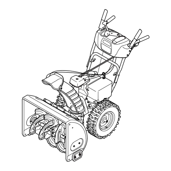
26" SNOW THROWER
Model No. 247.889703
CAUTION: Before using
this product, read this
manual and follow all
safety rules and operating
instructions.
Sears Brands Management Corporation, Hoffman Estates, IL 60179, U.S.A.
®
Visit our website: www.craftsman.com
• SAFETY
• ASSEMBLY
• OPERATION
• MAINTENANCE
• PARTS LIST
• ESPAÑOL
FORM NO. 769-05136D
6/06/2011
Advertisement
Chapters
Table of Contents

Related Manuals for Craftsman 31AS63TF799


Summary of Contents for Craftsman 31AS63TF799
- Page 1 • MAINTENANCE • PARTS LIST CAUTION: Before using • ESPAÑOL this product, read this manual and follow all safety rules and operating instructions. Sears Brands Management Corporation, Hoffman Estates, IL 60179, U.S.A. Visit our website: www.craftsman.com FORM NO. 769-05136D 6/06/2011...
-
Page 2: Table Of Contents
This warranty is void if this product is ever used while providing commercial services or if rented to another person. For warranty coverage details to obtain repair or replacement, visit the web site: www.craftsman.com This warranty covers ONLY defects in material and workmanship. Warranty coverage does NOT include: •... -
Page 3: Safe Operation Practices
SAFETY INSTRUCTIONS WARNINg DANgER This machine was built to be operated according to the safe opera- This symbol points out important safety instructions which, if not tion practices in this manual. As with any type of power equipment, followed, could endanger the personal safety and/or property of carelessness or error on the part of the operator can result in serious yourself and others. - Page 4 SAFETY INSTRUCTIONS Safe Handling of Gasoline • Exercise extreme caution when operating on or crossing gravel surfaces. Stay alert for hidden hazards or traffic. To avoid personal injury or property damage use extreme care in handling gasoline. Gasoline is extremely flammable and the vapors are •...
- Page 5 SAFETY INSTRUCTIONS MAINTENANCE & STORAgE DO NOT MODIFY ENgINE • Never tamper with safety devices. Check their proper operation To avoid serious injury or death, do not modify engine in any way. regularly. Refer to the maintenance and adjustment sections of Tampering with the governor setting can lead to a runaway engine and this manual.
- Page 6 SAFETY INSTRUCTIONS SAFETY SYMBOLS This page depicts and describes safety symbols that may appear on this product. Read, understand, and follow all instructions on the machine before attempting to assemble and operate. Symbol Description READ THE OPERATOR’S MANUAL(S) Read, understand, and follow all instructions in the manual(s) before attempting to assemble and operate WARNING—...
- Page 7 This page left intentionally blank.
-
Page 8: Assembly
ASSEMBLY NOTE: References to right or left side of the snow thrower are determined from behind the unit in the operating position (standing directly behind the snow thrower, facing the handle panel). Chute Control Head REMOVINg FROM CARTON Chute Support Cut the corners of the carton and lay the sides flat on the ground. - Page 9 ASSEMBLY Place chute onto chute base and ensure chute control rod is Chute Control positioned under handle panel. Install hex bolt previously removed Top View Input but do not secure with wing nut at this time. See Figure 4. Squeeze the trigger on the handle panel joystick and rotate the chute by hand to face forward.
- Page 10 ASSEMBLY 7. Make sure all cables are routed to the left of the chute control rod. Line up the hole in the rod with the arrow on the input shaft and insert the rod into the input shaft below joystick on handle panel.
- Page 11 ASSEMBLY 10. Check that all cables are properly routed through the cable guide on the engine. See Figure 10. NOTE: If the chute control is not assembled correctly it will not move freely nor will it move fully to the right and left. 11.
- Page 12 ASSEMBLY Chute Clean-Out Tool A chute clean-out tool is fastened to the top of the auger housing with a mounting clip. See Figure 12. The tool is designed to clear a chute assembly of ice and snow. This item is fastened with a cable tie at the factory.
- Page 13 ASSEMBLY Auger Control WARNINg Prior to operating your snow thrower, carefully read and follow all instructions below. Perform all adjustments to verify your snow thrower is operating safely and properly. Check the adjustment of the auger control as follows: When the auger control is released and in the disengaged “up” position, the cable should have very little slack.
-
Page 14: Operation
(2) is the faster. and aids in starting the engine. CHUTE ASSEMBLY Snow drawn into the auger housing is discharged out the chute assembly. Meets ANSI Safety Standards Craftsman Snow Throwers conform to the safety standard of the American National Standards Institute (ANSI). - Page 15 OPERATION THROTTLE CONTROL DRIVE CONTROL/ AUgER CONTROL LOCk DRIVE CONTROL The throttle control is located on the rear of the engine. It regulates the speed of the engine and will shut off the engine when moved into the STOP position. PRIMER Depressing the primer forces fuel directly into the engine’s carburetor to aid in cold-weather...
- Page 16 OPERATION CLEAN-OUT TOOL • Refuel in a well-ventilated area with the engine stopped. Do not smoke or allow flames or sparks in the area where the engine is WARNINg refueled or where gasoline is stored. Never use your hands to clear a clogged chute assembly. Shut •...
- Page 17 OPERATION TO ENgAgE DRIVE Move throttle control to FAST (rabbit) position. Move choke to the CHOKE position (cold engine start). If With the throttle control in the Fast (rabbit) position, move engine is warm, place choke in RUN position. shift lever into one of the six forward (F) positions or two reverse Push primer three (3) times, making sure to cover vent hole when (R) positions.
-
Page 18: Service &Maintenance
SERVICE AND MAINTENANCE MAINTENANCE SCHEDULE WARNINg Before performing any type of maintenance/service, disengage all Follow the maintenance schedule given below. This chart describes controls and stop the engine. Wait until all moving parts have come to service guidelines only. Use the Service Log column to keep track of completed maintenance tasks. - Page 19 SERVICE AND MAINTENANCE Changing Engine Oil NOTE: Change the engine oil after the first 5 hours of operation and once a season or every 50 hours thereafter. Drain fuel from tank by running engine until the fuel tank is empty. Be sure fuel fill cap is secure.
- Page 20 SERVICE AND MAINTENANCE Measure the plug gap with a feeler gauge. Correct as necessary by bending side electrode. See Figure 20. The gap should be set to .02-.03 inches (0.60-0.80 mm). Electrode Check that the spark plug washer is in good condition and thread the spark plug in by hand to prevent cross-threading.
- Page 21 SERVICE AND MAINTENANCE SHAVE PLATE AND SkID SHOES The shave plate and skid shoes on the bottom of the snow thrower are subject to wear. They should be checked periodically and replaced when necessary. NOTE: The skid shoes on this machine have two wear edges. When one side wears out, they can be rotated 180°...
- Page 22 SERVICE AND MAINTENANCE Chute Control Rod To achieve more chute control rod engagement in the input shaft under the handle panel, the chute control rod will have to be adjusted. Refer to Figure 26. To adjust this rod, proceed as follows: Remove the cotter pin from the hole closest to the chute control head on the chute control input.
- Page 23 SERVICE AND MAINTENANCE Carefully pivot the snow thrower up and forward so that it rests on the auger housing. Remove the frame cover from the underside of the snow thrower by removing the self-tapping screws which secure it. See Figure Remove the belt as follows.
- Page 24 SERVICE AND MAINTENANCE Drive Belt To remove and replace your snow thrower’s drive belt, proceed as follows: To prevent spillage, remove all fuel from tank by running engine until it stops. Remove the plastic belt cover on the front of the engine by remov- ing the two self-tapping screws.
- Page 25 SERVICE AND MAINTENANCE Carefully remove the hex nut and washer which secures the hex shaft to the snow thrower frame and lightly tap the shaft’s end to dislodge the ball bearing from the right side of the frame. See Figure 35. NOTE: Be careful not to damage the threads on the shaft.
-
Page 26: Off-Season Storage
OFF-SEASON STORAGE If the snow thrower will not be used for 30 days or longer, or if it is the end of the snow season when the last possibility of snow is gone, the equipment needs to be stored properly. Follow storage instructions below to ensure top performance from the snow thrower for many more years. PREPARINg SNOW THROWER PREPARINg ENgINE •... -
Page 27: Troubleshooting
TROUBLESHOOTING Problem Cause Remedy Engine fails to start Choke control not in CHOKE position. Move choke control to CHOKE position. Spark plug wire disconnected. Connect wire to spark plug. Faulty spark plug. Clean, adjust gap, or replace. Fuel tank empty or stale fuel. Fill tank with clean, fresh gasoline. -
Page 28: Parts List
PARTS LIST Craftsman Snow Thrower Model 247.889703... - Page 29 PARTS LIST Craftsman Snow Thrower Model 247.889703 Ref. No. Part No. Description Ref. No. Part No. Description 931-2643 Clean-Out Tool 741-0663 Flange Bearing 712-04065 Flange Lock Nut 710-0642 Screw, 1/4-20 x 0.75 756-04224 Flat Idler Pulley 790-00087A-0637 Bearing Housing 710-0347 Hex Bolt, 3/8-16 x 1.75...
- Page 30 PARTS LIST Craftsman Snow Thrower Model 247.889703...
- Page 31 PARTS LIST Craftsman Snow Thrower Model 247.889703 Ref. No. Part No. Description Ref. No. Part No. Description 684-04112B Handle Engagement Assembly RH 984-04338 4-Way Chute Control™ Assembly 738-04367 Flange Shoulder Screw 749-04191A-0637 Upper Handle LH 731-04894D Lock Plate 710-04326 Screw, #8-16 x 0.50...
- Page 32 PARTS LIST Craftsman Snow Thrower Model 247.889703...
- Page 33 PARTS LIST Craftsman Snow Thrower Model 247.889703 Ref. No. Part No. Description Ref. No. Part No. Description 656-04055 Disc Assembly, Friction Wheel 735-04099 Plug, 3/8 ID 684-04153 Friction Wheel Assembly, 5.5 OD 710-0809 Hex Screw, 1/4-20, 1.25, Gr5 684-04154B-0637 Support Bracket, Friction Wheel 710-0191 Hex Screw, 3/8-24, 1.25, Gr8...
- Page 34 PARTS LIST Craftsman Snow Thrower Model 247.889703 777S32636 777D16339 777S32236 777I22339 777D16338 777D16341 OVERHEAD VALVE 777I22363 777D16340 777X43688 777I22435 AUGER CONTROL DRIVE CONTROL 777D16357 ” CLEARING WIDTH ELECTRIC START ELECTRIC START...
- Page 35 NOTES...
- Page 36 MTD CONSUMER gROUP INC (MTD), the California Air Resources Board (CARB) and the United States Environment Protection Agency (U. S. EPA) Emission Control System Warranty Statement (Owner’s Defect Warranty Rights and Obligations) EMISSION CONTROL SYSTEM COVERAGE IS APPLICABLE TO CERTIFIED ENGINES PURCHASED IN CALIFORNIA IN 2005 AND THERE- AFTER, WHICH ARE USED IN CALIFORNIA, AND TO CERTIFIED MODEL YEAR 2005 AND LATER ENGINES WHICH ARE PURCHASED AND USED ELSEWHERE IN THE UNITED STATES.
- Page 37 (4) Repair or replacement of any warranted part under the warranty provisions of this article must be performed at no charge to the owner at a warranty station. (5) Notwithstanding the provisions of Subsection (4) above, warranty services or repairs must be provided at all MTD distribution centers that are franchised to service the subject engines.
- Page 38 Look For Relevant Emissions Durability Period and Air Index Information On Your Engine Emissions Label Engines that are certified to meet the California Air Resources Board (CARB) Tier 2 Emission Standards must display information regarding the Emissions Durability Period and the Air Index. Sears Brands Management Corporation makes this information available to the consumer on our emission labels.
-
Page 39: Repair Protection Agreement
REPAIR PROTECTION AGREEMENT Congratulations on making a smart purchase. Your new Craftsman® Once you purchase the Agreement, a simple phone call is all that it product is designed and manufactured for years of dependable opera- takes for you to schedule service. You can call anytime day or night, or tion. -
Page 40: Español
La presente garantía se anula si se utiliza este producto alguna vez para prestar servicios comerciales o si se lo alquila a otra persona. Para obtener información sobre el alcance de la garantía y solicitar la reparación o el reemplazo, visite el sitio Web: www.craftsman.com Esta garantía cubre ÚNICAMENTE los defectos en los materiales y en la mano de obra. -
Page 41: Prácticas Operación Seguras
INSTRUCCIONES DE SEGURIDAD ADVERTENCIA PELIgRO Esta máquina fue construida para ser operada de acuerdo con La presencia de este símbolo indica que se trata de instrucciones las reglas de seguridad contenidas en este manual. Al igual que importantes de seguridad que se deben respetar para evitar con cualquier tipo de equipo motorizado, un descuido o error por poner en peligro su seguridad personal y/o material y la de otras parte del operador puede producir lesiones graves. - Page 42 INSTRUCCIONES DE SEGURIDAD Manejo seguro de la gasolina • Nunca opere la máquina si falta un montaje del canal o si el mismo está dañado. Mantenga todos los dispositivos de seguri- Para evitar lesiones personales o daños materiales tenga mucho dad en su lugar y en funcionamiento.
- Page 43 INSTRUCCIONES DE SEGURIDAD • Para encender el motor, jale de la cuerda lentamente hasta que • Según la Comisión de Seguridad de Productos para el Consu- sienta resistencia, luego jale rápidamente. El repliegue rápido de midor de los Estados Unidos (CPSC) y la Agencia de Protección la cuerda de arranque (tensión de retroceso) le jalará...
- Page 44 INSTRUCCIONES DE SEGURIDAD SÍMBOLOS DE SEgURIDAD Esta página describe los símbolos y figuras de seguridad internacionales que pueden aparecer en este producto. Lea el manual del operador para obtener la información terminada sobre seguridad, reunirse, operación y mantenimiento y reparación. Símbolo Descripción LEA EL MANUAL DEL OPERADOR (S)
-
Page 45: Montaje
MONTAJE NOTA: las referencias al lado derecho o y ciertos de la máquina quitanieve se determinan desde la parte posterior de la unidad en Cabezal de posición de operación (permaneciendo directamente detrás de la Control del máquina quitanieve, mirando hacia el panel de la manija). Canal Ménsula ExTRACCIóN DE LA UNIDAD DE LA CAjA... - Page 46 MONTAJE 4. Ubique el canal sobre la base del mismo y garantizar la varilla hex Cabezal de agonal está situado bajo el panel manejar. Instalar el perno Control del Vista desde Arriba hexagonal previamente eliminado, pero no seguro con tuerca de Canal mariposa en este momento.
- Page 47 MONTAJE 7. Inserte la varilla hexagonal dentro del engranaje del piñón por debajo de la palanca de control. Asegúrese de alinear el orificio en la varilla hexagonal con la flecha en el engranaje del piñón. Vea la figura 7. NOTA: El orificio es una referencia para alinear la varilla con la flecha indicadora en el engranaje del piñón.
- Page 48 MONTAJE 10. Controle que todos los cables estén adecuadamente dirigidos a través de la guía de cables en el motor. Vea la figura 10. NOTA: Para más suave funcionamiento, los cables deben estar a la izquierda de la varilla hexagonal. 11.
- Page 49 MONTAJE Herramienta de Limpieza del Canal Hay una herramienta de limpieza del canal iajustada a la parte superior de la caja de la barrena con un pasador de ensamblado. Vea la figura 12. La herramienta está diseñada para limpiar el hielo y la nieve del montaje de un canal.
- Page 50 MONTAJE NOTA: Si tiene que usar la máquina quitanieve sobre grava, mantenga la zapata antideslizante en la posición más elevada para lograr una separación máxima entre el piso y la placa de raspado. Para ajustar las zapatas antideslizantes: Afloje las cuatros tuercas hexagonales (dos en cada lado) y los pernos del carro.
-
Page 51: Operación
La nieve retirada al interior de la caja de la barrena se descarga en el montaje del canal. Cumple con los estándares de seguridad de ANSI Las máquinas quitanieve de Craftsman cumplen con los estándares de seguridad del instituto estadounidense de estándares nacionales (ANSI). - Page 52 OPERACIÓN CONTROL DEL ESTRANgULADOR CONTROL DE LA BARRENA El control del estrangulador está ubicado en el motor. Regula la velocidad del motor, y lo apaga cuando mueva el control a la posición STOP. CEBADOR Al presionar el cebador se envía combustible directamente al carburador del motor para CONTROL DE LA TRANSMISIóN/ CONTROL ayudar al encendido cuando el clima es frío.
- Page 53 OPERACIÓN NOTA: No lo llene en exceso. El llenado excesivo de aceite puede • Cambiar la dirección en la cual la nieve es lanzada, apretón el botón en la palanca de mando y pivote la palanca de mando a la hacer que el motor genere humo, que cueste arrancarlo o fallas en la derecha o a la izquierda.
- Page 54 OPERACIÓN Arrancador eléctrico Mueva la palanca del cebador hasta la posición CHOKE ADVERTENCIA (encendido con el motor en frío). Si el motor ya está caliente, ubique el cebador en la posición RUN. El arrancador eléctrico opcional está equipado con un cable de ali- Presione el cebador tres (3) veces, asegurándose de cubrir el mentación y un enchufe de tres terminales conectados a tierra y está...
-
Page 55: Servicio Y Mantenimiento
SERVICIO Y MANTENIMIENTO LISTA DE MANTENIMIENTO ADVERTENCIA Antes de realizar cualquier tipo del mantenimiento/servicio, suelte Siga la lista de mantenimiento dada abajo. Esta carta describe pautas todos los mandos y pare el motor. Espere hasta que todas las partes de servicio sólo. Use la columna de Tronco de Servicio para guardar de movimiento hayan venido a una parada completa. - Page 56 SERVICIO Y MANTENIMIENTO Ajuste firmemente la varilla de medición antes de arrancar el motor. Cambio de aceite del motor NOTA: Cambie el aceite después de las 5 primeras horas de operación y después de cada 50 horas de operación o una vez por temporada.
- Page 57 SERVICIO Y MANTENIMIENTO Mida l a separación de bujía con un calibrador. Corrija de ser necesario torciendo el electrodo lateral. Vea la Figura 19. La separación debe establecerse entre 0,02 y 0,03 pulgadas (0,60- Electrodo 0,80 mm). Verifique que la arandela de la bujía esté en buenas condiciones y enrósquela manualmente para no estropear la rosca.
- Page 58 SERVICIO Y MANTENIMIENTO Monte las nuevas zapatas antideslizantes con cuatros pernos de carro (dos en cada lado) y las tuercas de brida hexagonales. Consulte la figura 22. Para retirar la placa de raspado: Quite los pernos de carro y las tuercas hexagonales que la sujetan a la caja de la máquina quitanieve.
- Page 59 SERVICIO Y MANTENIMIENTO Varilla de control del canal Para lograr una mayor engagment varilla hexagonal en el piñón de artes en el marco del panel de manejar, es necesario ajustar la varilla de control del canal. Para ajustar este varilla, proceda de la siguiente manera: Retire el pasador de chaveta del orificio más cercano al conjunto del canal sobre el montaje de rotación del canal.
- Page 60 SERVICIO Y MANTENIMIENTO Afloje y retire el tornillo con reborde que actúa como guarda de la correa. Vea la figura 29. Desenganche el resorte de la ménsula de soporte del marco. Retire la correa de alrededor de la polea de la barrena y deslice la misma entre la ménsula de soporte y la polea de la barrena.
- Page 61 SERVICIO Y MANTENIMIENTO 6. Detrás la parada se escapa para aumentar la autorización entre el disco de rueda de fricción y rueda de fricción. Vea la figura 32. 7. Deslice la correa de la transmisión fuera de la polea y de entre la rueda de fricción y el disco de la rueda de fricción.
- Page 62 SERVICIO Y MANTENIMIENTO NOTA: Tenga cuidado de no dañar las roscas del eje. Con cuidado, ubique el eje hexagonal hacia abajo y hacia la izquierda antes de deslizar con precaución el montaje de la rueda de fricción fuera del eje. Vea la figura 35. NOTA: Cuando se desea reemplazar el conjunto de la rueda de fricción completo, descarte la pieza desgastada y deslice la nueva pieza en el eje hexagonal.
-
Page 63: Almacenamiento Fuera De Temporada
ALMACENAMIENTO FUERA DE TEMPORADA Si no se va a utiliza el equipo durante 30 días o más, o si es el final de la temporada de nieve y ya no existe posibilidad de que nieve, es necesario almacenar el equipo de manera adecuada. Siga las instrucciones de almacenamiento que se indican a continuación para garantizar el rendimiento máximo de la máquina quitanieve durante muchos años . -
Page 64: Solución De Problemas
SOLUCIÓN DE PROBLEMAS Problema Causa Remedio El motor no arranca La palanca de obturación no está en la Ponga el interruptor en la posición CHOKE (obtura- posición ON (encendido) ción). Se ha desconectado el cable de la bujía Conecte el cable a la bujía. La bujía no funciona correctamente Limpie, ajuste la distancia disruptiva o cambie. - Page 65 SOLUCIÓN DE PROBLEMAS Problema Causa Remedio Pérdida de potencia El cable de la bujía está flojo Conecte y ajuste el cable de la bujía. El orificio de ventilación del tapón de Retire el hielo y la nieve del tapón de llenado del llenado del combustible está...
- Page 66 MTD CONSUMER gROUP, INC. (MTD), el Bordo de Recursos de Aire de California (CARB) y la Agencia de Protección Medioambiental de Estados Unidos (U. S. EPA) Declaración de garantía del Sistema de Control de Emisiones (Derechos y obligaciones del propietario según la garantía contra defectos) LA COBERTURA DE SISTEMA DE CONTROL DE EMISIÓN ES APLICABLE A MOTORES CERTIFICADOS COMPRADOS EN CALIFORNIA EN 2005 Y A PARTIR DE ENTONCES, QUE SON USADOS EN CALIFORNIA, Y HASTA AÑO 2005 DE MODELO CERTIFICADO Y MOTORES POSTERIORES QUE SON COMPRADOS Y USADOS EN OTRA PARTE EN LOS ESTADOS UNIDOS.
- Page 67 reemplazada según la garantía se garantizará por el resto del período de garantía. Cualquier pieza garantizada que esté programada para reemplazo según el mantenimiento requerido de conformidad con las instruc- ciones escritas de la Subsección (c) se garantiza por el período de tiempo anterior a la primera fecha de reemplazo programada para esa pieza.
- Page 68 Busque el período de duración de emisiones importantes yla información de clasificación de aire en la etiqueta de emisiones de su motor Los motores cuyo cumplimiento con los estándares de emisión Tier 2 de la Comisión de Recursos Ambientales de California (CARB) esté...
-
Page 69: Acuerdo De Protección Para Reparaciones
Felicitaciones por haber realizado una adquisición inteligente. El Una vez adquirido el Acuerdo, puede programar el servicio con producto Craftsman® que ha adquirido está diseñado y fabricado tan sólo realizar una llamada telefónica. Puede llamar en cualquier para brindar muchos años de funcionamiento confiable. Pero como momento del día o de la noche o programar un servicio en línea. - Page 70 NOTAS...
- Page 71 NOTAS...
- Page 72 Get it fixed, at your home or ours! Your Home For troubleshooting, product manuals and expert advice: www.managemylife.com For repair – in your home – of all major brand appliances, lawn and garden equipment, or heating and cooling systems, no matter who made it, no matter who sold it! For the replacement parts, accessories and owner’s manuals that you need to do-it-yourself.
Need help?
Do you have a question about the 31AS63TF799 and is the answer not in the manual?
Questions and answers