Table of Contents
Advertisement
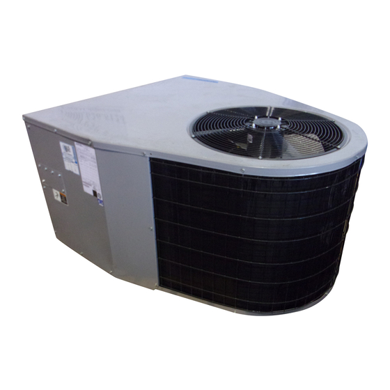
Installation Instructions
I
DIRECT
DRIVE BLOWER
Three Phase
PA55/PAPA SERI ES
SINGLE PACKAGE AIRCONDITIONERS
ELECTRIC
/
@
ELECTRIC HEAT (OPTIONAL)c
TABLEOF CONTENTS
1, Safety Labelingand Signal Words ..........................
2
Danger, Warning and Caution
...................................
2
2. Safe Installation
Requirements
.....................
2
3. Locating The Unit ..................................
2
Clearances
...................................................
2
Dimensions
...................................................
2
Minimum Clearances
to ComLJstibte Construction
3
Installation
...................................................
3
Installing Duct Collars
.. 3
_'ondensate Drain
,1
4. Electrical
Wiring
..................................
4
Ground Connections
...........................................
4
Line Voltage Wiring
............................................
4
Unit Disconnect
...............................................
4
Converting
230M tJnils to 208V
...................................
4
Low Voltage Wiring
...........................................
4
Thermostat
Connections
........................................
5
Field Installed
Equipment
........................................
5
5. Electric
Heat Installation
.............................
6
General Information
..........................................
6
Adjustinc Thermostat
Anticipator
.......
6
Limit Controls
.......
6
Operation
........
6
Install Heater .................................................
6
Heater Wiring
.................................................
6
Grounding
.....................
6
Installing Wrong
6
Unit Disconnect
Breaker
.........................................
8
Rain Shield Installation
........................................
8
6. Air Distribution
System
..............................
8
Ductwork ....................................................
8
DuctworkInsulation.. .....
8
DactwerkConnections........
8
Filters ........................................................
8
7. Start-up
Procedul'es
................................
9
Final Electrical Check ...........................................
9
Circulating Air Blower .........................................
9
DeterminingE ower Speed .........
g
BDeedTai3s ..................
9
Cooling and AuxiliaryElectric StripHeat ............................
9
Check Before Starting ..........................................
9
CirculatingAir Blower
.........
10
Cooling
.....................................
10
Auxiliary _ea[mg .........................
10
Temperature Rise Check .....
i,,.
................................
10
Sequence of Operation ,
....................................
10
Cooling Mode:Energizan RGY'_) De_ene_gized(NA
...............
10
8. Operation
............................................
11
ScrollAnti-Cycle Timer {Wh_reApplicai:31e} .........................
11
Turning The UnitOff ...............................................
11
ThermostatFanSwitch Operation...,,
...........................
11
AdjustingRoom Temperatures ....
..,
...........................
11
13, Maintenance
......................................
11
MonthlyMaintenanceand Inspection Checks .......................
11
Air Fitters
.
11
Cooling Season Checks (Monthly} ................................
11
CondenserCo
.....
11
CondensateDrain...
11
Annual Maintenance and inspection ..............................
1t
Condenser Fan Motor
11
CircaiatingAir Blower
12
Printed in U.S.A.
426 O1 1OO5 CO
1o/15/Ol
Advertisement
Table of Contents

Related Manuals for ICP PA55 Series


Summary of Contents for ICP PA55 Series
- Page 1 Installation Instructions DIRECT DRIVE BLOWER Three Phase PA55/PAPA SERI ES SINGLE PACKAGE AIRCONDITIONERS ELECTRIC ELECTRIC HEAT (OPTIONAL)c TABLEOF CONTENTS 1, Safety Labelingand Signal Words ......6. Air Distribution System ......Ductwork ............ Danger, Warning and Caution ........DuctworkInsulation..2. Safe Installation Requirements .....
-
Page 2: Safety Labeling And Signal Words
1. Safety Labeling and Signal Words CAUTION Danger, Warning and Caution Do NOT operate unit in a corrosive atmosphere containing The signal words DANGER, WARNING and CAUTION are used chlorine, fluorine, or any other corrosive chemicals. to identify levels of hazard seriousness. -
Page 3: Installation
Minimum Clearances to Combustible Construction ..SERVICE ACCESS CLEARANCES Blower Access Pane! Side ....30" (762mm) Electrical Access Panel Side ....30" (762mm) OPERATIONAL CLEARANCES Combustible Base (Wood or Class A, B or C roof covering material) ....0" Supply and Return Air Ducts ...... -
Page 4: Electrical Wiring
Condensate Drain FIGURE 4 J Condensate Drain Information* 3/4" (19.1mm) The condensate drain outlet is (19.1 mm) threaded female a 3/4" Threaded Female PVC connection located at the bottom of the unit to the left of the PVC Fitting evaporator access panel. -
Page 5: Low Voltage Wiring
Thermostat Connections Field Installed Equipment Wiring to be done in the field between the unit and other devices, The location of the thermostat has an important effect on the op- or between separate devices which are field installed and located, eration of the unit. -
Page 6: Electric Heat Installation
5. Electric Heat Installation General Information FIGURE 8 Electric Heat Accessory Adjusting Thermostat Anticipator Set the heat anticipator of the thermostat to the proper value. See instructions provided with the thermostat before making this ad- justment. Model Number Anticipator Setting AMMH10AHB :Z_ ii i AMMH15AHB... - Page 7 1. Shut OFF electric power at unit disconnect or service panel. 5. Connect the black wire with terminal from the heater wire harness to the loose black wire at the unit blower or appropri- ate speed tap if lower speed is desired in electric heat mode.
-
Page 8: Air Distribution
6. Air Distribution System For airflow data (blower performance data, blower speed tap set- Refer to unit rating plate for proper Electric Heat Accessory sizing tings, etc.) see the Technical Data Sheet attached to the unit.. and see the Temperature Rise Check section in the Electric Heat... -
Page 9: Final Electrical Check
7. Start-up Procedures applied to the unit, it is the responsibility of the installing dealer contractor to select the proper speed taps for the application when the unit is installed. Electrical shock hazard. Motor Speed Taps IO.ow., Use extreme care during all of the following checks and pro- cedures. -
Page 10: Cooling
NOTE: The temperature rise can be adjusted by changing the Circulating Air Blower speed tap at the unit's blower terminal block. Refer to the unit's Installation Instructions for airflow information. 1. Be sure electric power is OFF. A temperature rise greater than 60°F (33.3°C) is not recom- mended. -
Page 11: Operation
8. Operation Turning The Unit Off Electrical shock hazard. 1. Set the thermostat selector switch to OFF and set the fan switch to AUTO. To restart, set thermostat selector switch Turn OFF electric power supply at disconnect switch or ser- COOL or HEAT and set thermostat to temperature... - Page 12 Circulating Air Blower mulation is excessive on blower wheel, or does not easily remove, it may be necessary to remove and disassemble To access or remove the blower motor use the following steps. blower assembly for proper cleaning. 1. Turn electric power OFF. 6.
- Page 13 INTERNATIONAL COMFORT PRODUCTS LIMITED WARRANTY CERTIFICATE For Cooling & Heating Products SAVE THIS CERTIFICATE. It gives you specific legal rights, and you may also have other rights which may vary from state to state and province to province. If your unit needs servicing, contact a qualified dealer or qualified service technician of your choice. When requesting service, please have the model and serial number from each unit in your heating and/or cooling system readily available.
- Page 14 ADDITIONAL TERMS FOR RESIDENTIAL APPLICATIONS ONLY The Additional Terms for the components listed below are in addition to, and subject to, the General Terms on the reverse side of this page. Warranty coverage is limited to parts that fail due to defect in materials or workmanship during the specified term.
Need help?
Do you have a question about the PA55 Series and is the answer not in the manual?
Questions and answers
how much does it weigh