
Subscribe to Our Youtube Channel
Related Manuals for Vizio XMA500


Summary of Contents for Vizio XMA500
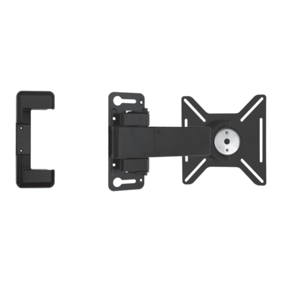
- Page 1 FULL ARTICULATING MOUNT UNIVERSAL FOR 26” - 37” TVS UP TO 50 LBS XMA500 - QUICK INSTALL GUIDE...
-
Page 2: Important Safety Information
IMPORTANT SAFETY INFORMATION Read the Important Safety Information on this page before installing or using this mounting system. Always follow the instructions in this Quick Install Guide. VIZIO is not liable for damage or injury caused by incorrect mounting, assembly, or use. -
Page 3: Step 1 - Before You Begin
STEP 1 - BEFORE YOU BEGIN TWO-PERSON JOB Before you begin the installation, ensure you have all of the items listed on this page. Do not begin the installation unless you have all of the following items. Mounting a TV requires power tools. If you are unfamiliar with safe power tool use, consult a professional installer. - Page 4 Before you begin, ensure all parts are included and undamaged. To prevent loss, do not unpack the small parts until they are required. If any parts are missing or damaged, contact VIZIO Customer Service (877) 698-4946. Quick Install Guide &...
- Page 5 MISC ANCHOR...
- Page 6 STEP 3 - CHOOSE THE DIRECTION OF SWING ARM The mount features an arm designed to swing away from the wall like a door. Like a door, the mount can swing open to the left or to the right. Before you begin the installation, you must decide which direction you want the arm to swing–to the left or to the right.
- Page 7 If you want the mount to swing to the right: 1. Lay the mount on the floor. Using the screwdriver, remove the 2 philips-head screws as shown. 2. Hold down the mount as shown and swing the arm away from the mount.
- Page 8 4. Gently separate the arm from the mount. Separate Arm from Mount 5. Flip the arm over, then gently reattach the arm to the mount. Flip Over Then Reattach 6. Using the phillips-head screwdriver, replace the 5 phillips-head screws.The arm is ready to swing to the right. •...
- Page 9 STEP 4A - MOUNTING TO A WALL WITH WOOD STUDS The mount can be attached to walls with wood studs. The wall covering (drywall, lath, plaster, etc.) may not be thicker than 1/2”. 1. Use the electronic stud finder to locate a stud in the wall. Use the pencil to mark the areas of the wall where the studs are located.
- Page 10 3. Using the power drill and the 7/32” drill bit, drill into the top template hole. Drill about 1/2” into the stud. Remove the template from the wall. 4. Remove 1 lag bolt and 1 large washer from the pouch labelled LAG.
- Page 11 5. Hold down the mount and swing the arm away from the mount. Use the philips-head screwdriver to remove the 2 screws as shown, then remove the plastic cover from the mount. Save the plastic cover. It will be reattached. 6.
- Page 12 7. Ensure the mount is level. Make any necessary adjustments, then use a pencil to mark the location of the remaining 3 holes as shown. Ensure the other lag bolt hole (#3 in diagram at right) is over the stud and aligned with the top lag bolt. Ensure lag bolt hole is over stud...
- Page 13 9. Remove the 2 small screws and 2 small washers from the pouch labeled LAG. Using a screwdriver, insert the 2 small screws and 2 small washers into the small holes on the mount. The small screws should be inserted completely into the plastic anchors. 10.
- Page 14 11. Put the plastic mount cover back into place and insert the 2 small screws as shown. Tighten the screws with the screwdriver. The mount is attached to the wall. Go to Step 5 on page 19.
- Page 15 STEP 4B - MOUNTING TO A CONCRETE WALL 1. Hold the template against the wall, using the level to level the Level template. When the template is level, tape it in place. 2. Using the power drill and the 1/2” drill bit, drill into the top template hole as shown.
- Page 16 3. Remove 1 metal anchor from the pouch labelled ANCHOR. Push the anchor into the hole you just drilled. Ensure the anchor is completely inserted and flush with the wall. 4. Remove 1 lag bolt and 1 large washer from the pouch labeled LAG.
- Page 17 5. Hold down the mount and swing the arm away from the mount. Use the philips-head screwdriver to remove the 2 screws as shown, then remove the plastic cover from the mount. Save the plastic cover. It will be reattached. 6.
- Page 18 7. Ensure the mount is level. Make any necessary adjustments, then use a pencil to mark the location of the remaining 3 holes as shown. 8. Swing the mount up and away from the marks you just made. Using the power drill and the 1/2” drill bit, drill into the lag bolt mark (#3 above).
- Page 19 9. Remove 2 plastic anchors from the pouch labeled ANCHOR. Push the 2 plastic anchors into the small holes as shown. Remove a metal anchor from the pouch labeled ANCHOR. Push the metal anchor into the large hole as shown. Ensure all anchors are inserted completely and are flush with the wall.
- Page 20 11. Remove the lag bolt and large washer from the pouch labeled LAG. Using a wrench, insert the lag bolt into the metal anchor. Tighten it completely. Tighten the top lag bolt completely. 12. Put the plastic mount cover back into place and insert the 2 small screws as shown.
- Page 21 STEP 5 - ATTACHING THE BACKPLATE TO YOUR TV 1. Using the screwdriver, remove the 4 screws from the swing arm as shown. There are 2 screws on the top and 2 inside the wire management canal on the bottom. Save the 4 screws.
- Page 22 Using the screwdriver, insert the screws, small washers, and large washers as shown. Because each TV is different, your VIZIO TV mount includes screws of different lengths. Use screws that can be inserted completely. Do not use a short screw if a longer screw can be [6, 7, 8] inserted completely.
- Page 23 STEP 6 - HANGING THE TV ON THE MOUNT This step requires lifting the TV. To prevent injury to yourself or damage to your TV, perform this step with the help of another person. Holes Facing Up 1. Swing the arm away from the mount. Swing Arm Away 2.
- Page 24 3. Align the screw holes according to the size of your TV: • For 26” TVs, use the innermost holes. • For 32” TVs, use the middle holes. • For 37” TVs, use the outermost holes. If your TV is wider than usual due to side speakers or a large frame/bezel, use holes set for a larger TV.
-
Page 25: Step 7 - Final Adjustments
STEP 7 - FINAL ADJUSTMENTS Using the included zip-ties, you can bundle and hide your TV’s cables. 1. To bundle and hide your TV’s cables, take the 4 zip-ties and 4 sticky mounts from the pouch labelled Sec X2. Bundle the cables together and wrap them with zip-ties. Before closing the zip-ties, lace each one through a sticky mount as shown. - Page 26 If necessary , you can adjust both the swivel and tilt of the TV. Remove the allen wrench from the pouch labeled Sec X2. 1. Using the allen wrench, adjust the swivel tension by adjusting the top and bottom screws as shown. 2.
-
Page 27: Warranty
IMPLIED WARRANTIES, INCLUDING ANY IMPLIED WARRANTY OF MERCHANTABILITY AND FITNESS VIZIO provides a warranty to the original purchaser of a new Product against defects in materials and FOR A PARTICULAR PURPOSE, SHALL BE LIMITED IN DURATION TO THE PERIOD OF TIME SET FORTH workmanship for a period of one year of non-commercial usage and ninety (90) days of commercial ABOVE. - Page 28 TRADEMARKS SHOWN ARE THE PROPERTY OF THEIR RESPECTIVE OWNERS. IMAGES USED ARE FOR ILLUSTRATION PURPOSES ONLY. VIZIO, THE V LOGO, WHERE VISION MEETS VALUE, AND OTHER VIZIO TRADEMARKS ARE THE INTELLECTUAL PROPERTY OF VIZIO INC. PRODUCT FEATURES AND SPECIFICATIONS ARE SUBJECT TO CHANGE WITHOUT NOTICE.
Need help?
Do you have a question about the XMA500 and is the answer not in the manual?
Questions and answers