
Related Manuals for Nvidia TF650i Ultra-A7


Summary of Contents for Nvidia TF650i Ultra-A7
- Page 1 User Guide TF650i Ultra-A7 Motherboard for Intel Processor Installation and Configuration...
-
Page 2: Table Of Contents
Installing and Configuring the TF650i Ultra-A7 Motherboard Table of Contents Before You Begin… ..................viii Parts NOT in the Kit..................viii Intentions of the Kit ..................ix Introduction ..................... 1 Features ......................1 Ultimate Overclocking ..................1 Guaranteed FSB speeds .................1 High-speed Memory..................1 Comprehensive Overclocking Tools ..............1 NVIDIA nTune Utility..................2 NV BIOS ....................2 True x16 PCI Express Support ................2... - Page 3 Preparing the Motherboard ................11 Installing the CPU..................11 Installing the CPU Fan..................12 Installing Memory DIMMs ................12 Installing the Motherboard................13 Installing the I/O Shield ................13 Securing the Motherboard into the Chassis............13 Connecting Cables and Setting Switches ............14 Power Connections ..................15 24-pin ATX Power (PWR1)................15 4-pin ATX 12V Power (PWR2) ..............16 Connecting IDE Hard Disk Drives..............16 Connecting Serial ATA Cables ...............16...
- Page 4 Installing and Configuring the TF650i Ultra-A7 Motherboard Main Menu......................25 Standard CMOS Features Menu ................28 Date and Time.....................29 IDE Channel and SATA Channel..............29 Drive A......................31 Halt On .......................31 Memory ......................32 Advanced BIOS Features..................33 Removable Device Priority................34 Hard Disk Boot Priority.................34 Network Boot Priority...................34 CPU Internal Cache..................34 Quick Power On Self Test................35 First/Second/Third Boot Device..............35...
- Page 5 NVMEM Memory Test...................48 Load Timing/Voltage Set ................48 Save Timing/Voltage Set ................49 System BIOS Cacheable ................49 HPET Function.....................49 NVIDIA GPU Ex ...................49 Integrated Peripherals Menu ................50 IDE Function Setup..................51 RAID Config ....................52 USB Config....................52 MAC Config ....................53 HD Audio ....................53 IDE HDD Block Mode ...................53 Onboard FDC Controller ................53 Onboard Serial Port 1...................53 Power Management Setup Menu ..............54...
- Page 6 Installing and Configuring the TF650i Ultra-A7 Motherboard PCI/VGA Palette Snoop ................58 Maximum Payload Size.................58 System Monitor Menu..................59 Dynamic Fan Control..................60 Index....................... 62...
- Page 7 List of Figures Figure 1. TF650i Ultra-A7 Motherboard Layout............8 Figure 2. Chassis Backpanel Connectors .............9 Figure 3. PWR1 Motherboard Connector............15 Figure 4. Expansion Slots ................22 Figure 5. BIOS CMOS Setup Utility Main Menu ..........26 Figure 6. Standard CMOS Features Menu ............28 Figure 7.
-
Page 8: Before You Begin
Before You Begin… Parts NOT in the Kit This kit contains all the hardware necessary to install and connect your new TF650i Ultra-A7 motherboard. However, it does not contain the following items that must be purchased separately to make the motherboard functional. Intel microprocessor: Intel Core 2 Extreme, Intel Core 2 Quad, Intel Core 2 Dual, Pentium Cooling fan for the microprocessor... -
Page 9: Intentions Of The Kit
Before You Begin Intentions of the Kit This kit provides you with the motherboard and all connecting cables necessary to install the motherboard into a PC cabinet. If you are building a PC, you will use most of the cables provided in the kit. If however, you are replacing a motherboard, you will not need many of the cables. -
Page 11: Introduction
Introduction Thank you for buying the TF650i Ultra-A7 Motherboard. This motherboard offers the tools and performance PC users’ demand. Features Ultimate Overclocking Unleash the underlying hardware. With comprehensive overclocking tools to push the limits on front side bus (FSB) speed and support for higher memory speeds, the NVIDIA nForce 650i Ultra MCPs were designed for overclocking. -
Page 12: Nvidia Ntune Utility
Installing and Configuring the TF650i Ultra-A7 Motherboard NVIDIA nTune Utility NVIDIA nTune is a Windows-based utility that has added access to more ™ settings. Adjust CPU and memory speeds without rebooting. You can also access most BIOS settings from inside Windows without having to go into the BIOS. -
Page 13: Diskalert System
Introduction DiskAlert System The event of a disk failure, MediaShield users see an image that highlights which disk has failed to make it easier to identify, replace, and recover. RAID Morphing MediaShield allows users to change their current RAID set-up to another configuration in a one-step process called morphing. -
Page 14: High Definition Audio (Hda)
Installing and Configuring the TF650i Ultra-A7 Motherboard High Definition Audio (HDA) High definition audio brings consumer electronics quality sound to the PC delivering high quality sound from multiple channels. Using HDA, systems can deliver 192 kHz/32-bit quality for eight channels, supporting new audio formats. USB 2.0 USB 2.0 is standard plug-and-play interface that provides easy-to-use connectivity for USB devices. -
Page 15: Motherboard Specifications
Introduction Motherboard Specifications Size ATX form factor of 12 inch x 9.6 inch Microprocessor support Intel Core 2 Extreme, Intel Core 2 Quad, Intel Core 2 Dual, Pentium Operating systems: Supports Windows XP 32bit/64bit and Windows Vista 32bit/64bit Contains NVIDIA nForce 650i Ultra MCP and SPP System Memory support Supports dual channel JEDEC DDR2-800. - Page 16 Installing and Configuring the TF650i Ultra-A7 Motherboard PCI Express x16 Support Supports 4 GB/sec (8 GB/sec concurrent) bandwidth Low power consumption and power management features Green Function Supports ACPI (Advanced Configuration and Power Interface) Supports S0 (normal), S1 (power on suspend), S3 (suspend to RAM), S4 (Suspend to disk - depends on OS), and S5 (soft - off) Expansion Slots Three PCI slots...
-
Page 17: Tf650I Ultra-A7 Motherboard
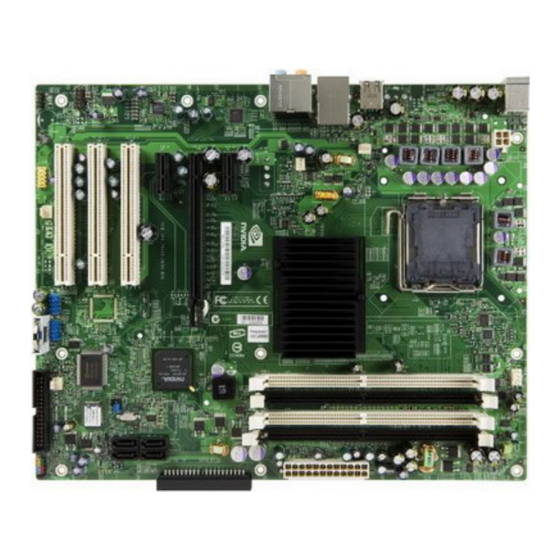
TF650i Ultra-A7 Motherboard The TF650i Ultra-A7 motherboard with the NVIDIA nForce 650i Ultra SPP and MCP processors is a PCI Express motherboard. Figure 1 shows the motherboard and Figures 2 shows the back panel connectors. -
Page 18: Figure 1. Tf650I Ultra-A7 Motherboard Layout
Installing and Configuring the TF650i Ultra-A7 Motherboard 1. CPU Socket 8. Serial-ATA connectors 15. PCI slots 2. NVIDIA SPP 9. Front panel connector 16. Front Panel Audio connector 3. CPU fan connector 10. Floppy drive connector 17. PCI Express x1 slot 4. -
Page 19: Figure 2. Chassis Backpanel Connectors
Introduction 1. PS/2 Mouse Port 2. PS/2 Keyboard Port 3. USB 2.0 ports (two) 4. Lan Port with LEDs to indicate status. • Yellow/Light Up/Blink = 10 Mbps/Link/Activity • Yellow and Green/Light Up/Blink = 100 Mbps/link/Activity • Green/Light Up/Blink = 1000 Mbps/Link/Activity 5. -
Page 20: Hardware Installation
Hardware Installation This section will guide you through the installation of the motherboard. The topics covered in this section are: Preparing the motherboard Installing the CPU Installing the CPU fan Installing the memory Installing the motherboard Connecting cables and setting switches Safety Instructions To reduce the risk of fire, electric shock, and injury, always follow basic safety precautions. -
Page 21: Preparing The Motherboard
Hardware Installation Preparing the Motherboard The motherboard shipped in the box does contain a CPU or memory. You need to purchase a CPU, a CPU fan assembly, and memory to complete this installation. Installing the CPU Be very careful when handling the CPU. Make sure not to bend or break any pins on the back. -
Page 22: Installing The Cpu Fan
Installing and Configuring the TF650i Ultra-A7 Motherboard Installing the CPU Fan There are many different fan types that can be used with this motherboard. Follow the instruction that came with you fan assembly. Be sure that the fan orientation is correct for your chassis type and your fan assembly. Installing Memory DIMMs Your new motherboard has four 1.8V 240-pin slots for DDR2 memory. -
Page 23: Installing The Motherboard
Hardware Installation Installing the Motherboard The sequence of installing the motherboard into the chassis depends on the chassis you are using and if you are replacing an existing motherboard or working with an empty chassis. Determine if it would be easier to make all the connections prior to this step or to secure the motherboard and then make all the connections. -
Page 24: Connecting Cables And Setting Switches
Installing and Configuring the TF650i Ultra-A7 Motherboard Connecting Cables and Setting Switches This section takes you through all the connections and switch settings necessary on the motherboard. This will include: Power Connections 24-pin ATX power ( PWR1 4-pin ATX 12V power ( PWR2 Internal Headers Front panel... -
Page 25: Power Connections
Hardware Installation Power Connections This motherboard requires an ATX power supply. Make sure you have enough power to cover all the expansion cards you will be installing. To determine what you power requirements are for your specific configuration, refer to www.slizone.com. -
Page 26: 4-Pin Atx 12V Power (Pwr2)
Installing and Configuring the TF650i Ultra-A7 Motherboard 4-pin ATX 12V Power (PWR2) , the 4-pin ATX 12V power connection, is used to provide power to the PWR2 CPU. Align the pins to the connector and press firmly until seated. Backpanel connector edge. Connecting IDE Hard Disk Drives The IDE connector supports Ultra ATA 133/100/66 IDE hard disk drives. - Page 27 Hardware Installation There are four serial ATA connectors on the motherboard that support RAID 0, RAID 1, RAID 5, RAID 0+1 and JBOD configurations. SATA 4 SATA 3 SATA 2 SATA 1 1. Connect the locking cable end to the motherboard connector.
-
Page 28: Connecting Internal Headers
Installing and Configuring the TF650i Ultra-A7 Motherboard Connecting Internal Headers Front Panel Header The front panel header on this motherboard is one connector used to connect the following four cables: PWRLED Attach the front panel power LED cable to HD_LED Connect RESET these two pins of the connector. - Page 29 Hardware Installation Table 2. Front Panel Header Pins Signal In/Out Description HD_PWR Hard disk LED pull-up to +5V HD_LED HDA# Hard disk active LED HDR_BLNK_GRN Front panel green light PWRLED HDR_BLNK_YEL Front panel yellow light Ground RESET FP_RESET# Reset switch SWITCH_ON# Power switch PWRSW...
-
Page 30: Usb Headers
Installing and Configuring the TF650i Ultra-A7 Motherboard USB Headers This motherboard contains four (4) USB 2.0 ports that are exposed on the rear panel of the chassis. The motherboard also contains two 10-pin internal header connectors onboard that can be used to connect an optional external bracket containing four (4) more USB 2.0 ports. -
Page 31: Fan Connections
Hardware Installation Fan Connections There are two fan connections, the system fan and the CPU fan. The fan speed can be detected and viewed in the PC Health Status section of the CMOS Setup. Both fans are automatically turned off after the system enters S3, S4 and S5 CPU fan connector mode. -
Page 32: Expansion Slots
Installing and Configuring the TF650i Ultra-A7 Motherboard Expansion Slots The TF650i Ultra-A7 motherboard contains six expansion slots, one PCI Express slot and three PCI slots. For a full list of PCI Express x16 graphics card supported by this motherboard, go to www.nvidia.com/estore. 1 –... -
Page 33: Pci Express X1 Slot
Hardware Installation PCI Express x1 Slot There are two PCI Express x1 slots that are designed to accommodate less bandwidth-intensive cards, such as a modem or LAN card. The x1 slot provides 250 MB/sec bandwidth. PCI Express x16 Slots There is one PCI Express x16 slot that is reserved for a graphics or video card. The bandwidth of the x16 slot is up to 4GB/sec (8GB/sec concurrent). -
Page 34: Configuring The Bios
Configuring the BIOS This section discusses how to change the system settings through the BIOS Setup menus. Detailed descriptions of the BIOS parameters are also provided. This section includes the following information: Enter BIOS Setup Main Menu Standard CMOS Features Advanced BIOS Features Advanced Chipset Features Integrated Peripherals... -
Page 35: Enter Bios Setup
Configuring the BIOS Enter BIOS Setup The BIOS is the communication bridge between hardware and software. Correctly setting the BIOS parameters is critical to maintain optimal system performance. Use the following procedure to verify/change BIOS settings. 1. Power on the computer, 2. -
Page 36: Figure 5. Bios Cmos Setup Utility Main Menu
Installing and Configuring the TF650i Ultra-A7 Motherboard Phoenix – AwardBIOS CMOS Setup Utility Standard CMOS Features System Monitor Advanced BIOS Features Load Defaults Advanced Chipset Features Set Password Save & Exit Setup Integrated Peripherals Power Management Setup Exit Without Saving PnP/PCI Configurations Esc : Quit : Select Item... - Page 37 Configuring the BIOS The following items on the CMOS Setup Utility main menu are commands rather than submenus: Load Defaults Load default system settings. Set Password Use this command to set, change, and disable the password used to access the BIOS menu.
-
Page 38: Standard Cmos Features Menu
Installing and Configuring the TF650i Ultra-A7 Motherboard Standard CMOS Features Menu The Standard CMOS Features menu is used to configure the standard CMOS information, such as the date, time, HDD model, and so on. Use the Page Up keys to scroll through the options or press to display the Page Down Enter... -
Page 39: Date And Time
Configuring the BIOS Date and Time Using the arrow keys, position the cursor over the month, day, and year. Use keys to scroll through dates and times. Note that Page Up Page Down the weekday (Sun through Sat) cannot be changed. This field changes to correspond to the date you enter. - Page 40 Installing and Configuring the TF650i Ultra-A7 Motherboard Press Enter to auto-detect IDE and SATA channels in the system. Once the channel is detected, the values for Capacity, Cylinder, Heads, Precomp, Landing Zone, and Sector are automatically filled in. None There is no HDD installed or set. Auto The system can auto-detect the hard disk when booting up.
-
Page 41: Drive A
Configuring the BIOS Drive A option allows you to select the kind of FDD to install. Drive A Options are: Press ENTER to display sub-menu Drive A [1.44, 3.5 in.] Halt On [All , But Keyboard] None Drive A 360K, 5.25 in. None .. -
Page 42: Memory
Installing and Configuring the TF650i Ultra-A7 Motherboard All, But Diskette The system boot does not stop for a diskette error but will stop for all other errors. All, But Disk/Key The system boot does not stop for a keyboard or disk error, but will stop for all other errors. -
Page 43: Advanced Bios Features
Configuring the BIOS Advanced BIOS Features Access the Advanced BIOS Features menu from the CMOS Utility Setup screen. Use the Page Up Page Down keys to scroll through the options or press to display the sub-menu. Use the arrow keys to position the Enter selector in the option you choose. -
Page 44: Removable Device Priority
Installing and Configuring the TF650i Ultra-A7 Motherboard Removable Device Priority Use this option to select the priority for removable device startup. Press Enter to see the list of removable devices in your system. Use the arrow keys to go to the various devices. Then use the keys to move the device priority up –... -
Page 45: Quick Power On Self Test
Configuring the BIOS Quick Power On Self Test Enabling this option allows the system to skip certain test while booting, which reduces the time needed to boot the system. Use the Page Up Page Down keys to toggle between Enable Disable First/Second/Third Boot Device Use this option to set the priority sequence of the devices booted at power on. -
Page 46: Security Option
Installing and Configuring the TF650i Ultra-A7 Motherboard Security Option The Security Options allows you to require a password every time the system boots or only when you enter setup. Select to require a password to gain Setup access to the CMOS Setup screen. Select to require a password to System access the CMOS Setup screen and when the system boots. -
Page 47: Advanced Chipset Features
Configuring the BIOS Advanced Chipset Features Select from the CMOS Setup Utility menu and Advanced Chipset Features press to display the functions of the Advanced Chipset Functions menu. Enter Phoenix – AwardBIOS CMOS Setup Utility Advanced Chipset Features System Clocks [Press Enter] Item Help FSB &... -
Page 48: System Clocks
Installing and Configuring the TF650i Ultra-A7 Motherboard System Clocks Select from the Advanced Chipset Features menu and press System Clocks to display the System Clocks menu. From this menu, you are able to Enter specify frequency settings, HT multipliers, and Spread Spectrum settings. Note that in Figure 9, all of the options are listed. -
Page 49: Frequency Settings
Configuring the BIOS Frequency Settings CPU Freq, MHz This value is set by the CPU Multiplier (value cannot be changed by the user). FSB Reference Clock. MHz This value is set by the system (value cannot be changed by the user). To change the FSB memory, and memory timing, go to the FSB &... -
Page 50: Ht Multiplier
Installing and Configuring the TF650i Ultra-A7 Motherboard HT Multiplier nForce SPP > nForce MCP — — Use the keys to scroll through the HT multiplier Page Up Page Down options and set the link speed from the SPP chip to the MCP chip. Values are through [1 x] [5 x]. -
Page 51: Fsb & Memory Config
Configuring the BIOS FSB & Memory Config Select from the Advanced Chipset Features menu and FSB & Memory Config press to display the FSB & Memory Config menu. This menu provides Enter the means to set FSB and memory timing. Phoenix –... - Page 52 Installing and Configuring the TF650i Ultra-A7 Motherboard CPU Freq, MHz 2933.3 2933.3 CPU Multiplier FSB – Memory Clock Mode [Linked] FSB (QDR), MHz [1067] 1066.7 Actual FSB (QDR), MHz 1066.7 x MEM (DDR), MHz Auto 800.6 Actual MEM (DDR), MHz 800.0 Unlinked When Unlink is selected,...
- Page 53 Configuring the BIOS Phoenix – AwardBIOS CMOS Setup Utility Memory Timing Setting Item Help Parameters Settings Current Value Memory Timing Setting [Optimal] Main Level x tCL (CAS Latency) Auto(5) x tRDC Auto(7) Select [Expert] to x tRP Auto(7) enter timings manually x tRAS Auto(23) x Command Per Clock (CDM)
- Page 54 Installing and Configuring the TF650i Ultra-A7 Motherboard Expert Use the keys to select . When Expert Page Up Page Down Expert is selected, all timing categories are enabled for manual input. Note that you should set the value to Optimal to use the manufacturers’ recommended values.
-
Page 55: Cpu Configuration
Configuring the BIOS CPU Configuration Select from the Advanced Chipset Features menu and CPU Configuration press to display the CPU Configuration menu. Enter Phoenix – AwardBIOS CMOS Setup Utility CPU Configuration Limit CPUID MaxVal [Disabled] Item Help x Intel SpeedStep Disabled CPU Thermal Control [Disabled]... -
Page 56: System Voltages
Installing and Configuring the TF650i Ultra-A7 Motherboard TM1 & TM2 Enables support for both TM1 and TM2. C1E Enhanced Halt State Enabled, this function reduces the CPU power consumption when the CPU is idle. Idle occurs when the operating system issues a halt instruction. Execute Disable Bit When this function is disabled, it forces the XD feature flag to always return to zero (0). - Page 57 Configuring the BIOS CPU Core Use the Page Up Page Down keys to scroll through the voltages or select to automatically set the voltage level for the CPU Core. [Auto] Memory This function defines the voltage level for the DRAM. Use the Page Up keys to select a voltage or select to automatically set the...
-
Page 58: Nvmem Memory Test
Installing and Configuring the TF650i Ultra-A7 Motherboard NVMEM Memory Test This function defines whether you run the NVIDIA memory testing module during POST. The options are Fast, Medium, Slow, and Disable. Load Timing/Voltage Set This function loads the system voltages and timing settings that were defined in the System Voltages menu. -
Page 59: Save Timing/Voltage Set
Configuring the BIOS Save Timing/Voltage Set This function saves the system voltages and timing settings that were defined in the System Voltages menu. There are four profile options that can be loaded. The default setting is for all settings. Press to see the options. -
Page 60: Integrated Peripherals Menu
Installing and Configuring the TF650i Ultra-A7 Motherboard Integrated Peripherals Menu Select from the CMOS Setup Utility menu and Integrated Peripherals press to display the Integrated Peripherals menu. Enter Phoenix – AwardBIOS CMOS Setup Utility Integrated Peripherals IDE Function Setup [Press Enter] Item Help RAID Config... -
Page 61: Ide Function Setup
Configuring the BIOS IDE Function Setup Press to display the IDE Function Setup menu. Enter OnChip IDE Channel0 [Enabled] Primary Master [Auto] Primary Slave [Auto] Primary Master UDMA [Auto] Primary Slave UDMA [Auto] IDE DMA transfer access [Enabled] Serial-ATA Controller [All Enabled] IDE Prefetch Mode [Enabled]... -
Page 62: Raid Config
Installing and Configuring the TF650i Ultra-A7 Motherboard RAID Config Press to display the RAID Config menu. Enter RAID Enable [Enabled] SATA 0 Primary RAID [Disabled] SATA 0 Secondary RAID [Disabled] SATA 1 Primary RAID [Disabled] SATA 1 Secondary RAID [Disabled] SATA 2 Primary RAID [Disabled]... -
Page 63: Mac Config
Configuring the BIOS MAC Config Press to display the MAC Config menu. Enter MAC0 LAN [Enabled] MAC1 LAN [Disabled] MACx LAN Use these functions to set the MAC0 and/or MAC1 LANs to Auto disable their functions. HD Audio This function on the Integrated Peripherals menu allows you to enable or disable the hard disk audio function. -
Page 64: Power Management Setup Menu
Installing and Configuring the TF650i Ultra-A7 Motherboard Power Management Setup Menu Select from the CMOS Setup Utility menu and Power Management Setup press to display the Power Management Setup menu. Enter Phoenix – AwardBIOS CMOS Setup Utility Power Management Setup ACPI function [Enabled] Item Help... -
Page 65: Soft-Off By Pbnt
Configuring the BIOS Soft-Off by PBNT This function on the Power Management Setup menu allows you to set Soft- Off by PBNT to [Instant-Off] [Delay 4 Sec] WOL(PME#) From Soft-Off This function on the Power Management Setup menu allows you to enable or disable WOL(PMW#) from soft-off. -
Page 66: Pnp/Pci Configuration Menu
Installing and Configuring the TF650i Ultra-A7 Motherboard Hot Key Power On When is selected, the function is enabled [Hot Key] Hot key Power On so that you must select a keyboard key as the hot key. To select a hot key use Ctrl+F1 though Ctrl+F12... -
Page 67: Init Display First
Configuring the BIOS Init Display First This function on the PnP/PCI Configuration menu allows you to define if the initial display is in the PCI slot or in the PCI Express slot. Options are [PCI Slot] [PCIEx]. Reset Configuration Data This function on the PnP/PCI Configuration menu allows you to enable or disable the resetting of Extended System Configuration Data (ESCD) when you exit Setup. -
Page 68: Irq Resources
Installing and Configuring the TF650i Ultra-A7 Motherboard IRQ Resources To enable this field for input, set Resources Controlled By . With this field enabled, press Enter to see options. [Manual] IRQ-5 assigned to [PCI Device] IRQ-9 assigned to [Reserved] IRQ-10 assigned to [PCI Device] IRQ-11 assigned to [PCI Device]... -
Page 69: System Monitor Menu
Configuring the BIOS System Monitor Menu Select from the CMOS Setup Utility menu and press Enter System Monitor display the System Monitor menu. Phoenix – AwardBIOS CMOS Setup Utility System Monitor Dynamic Fan Control [Press Enter] Item Help 47ºC/ 117ºF CPU Core 1.28V Main Level... -
Page 70: Dynamic Fan Control
Installing and Configuring the TF650i Ultra-A7 Motherboard Dynamic Fan Control Press Enter to display the Dynamic Fan Control menu. CPU Fan Speed Control [SmartFan] If temp > 70ºC, Set Fan Speed 100% If temp < 30ºC, Set Fan Speed Manual Fan Speed, % AUX Fan Speed Control, % [100] nForce Fan Speed Control, %... - Page 71 Configuring the BIOS This page is blank.
-
Page 72: Index
Index ACPI function.........54 Standard CMOS Features ....28 ACPI Suspend Type......54 System Clocks......38 Advanced BIOS Features ....33 System Monitor menu....59 Advanced Chipset Functions menu..37 System Voltages......46 Advanced Programmable Interrupt BIOS, configuring......24 Controller........36 block mode, IDE HDD ....53 APIC..........36 boot device priority ......35 ATX form factor .......5 C1E Enhanced Halt State ...46 auto-detect IDE and SATA channels 30... - Page 73 SATA .........16 FSB and Memory Clock Mode ..41 Cooling fan for CPU....... viii FSB Reference Clock ....39 CPU Configuration menu....45 FSB speeds........1 CPU cooling fan ......viii full-screen logo ......36 CPU Core 1 ........46 Gigabit Ethernet.......3 CPU fan........12, 21 Halt On sub-menu ......31 CPU Freq ........39 hard disk audio function ....53...
- Page 74 set system voltages in BIOS..46 memory support ......viii HPET..........49 Memory Timing Setting....42 HT Multiplier........40 microprocessor ......viii HT Spread Spectrum ....40 motherboard I/O shield ........13 install procedure......13 IDE connector........16 motherboard specifications ....5 IDE DMA transfer access ...51 MPS ..........36 IDE Function Setup menu....51 Multi-Processor Specification...36 IDE Prefetch Mode ......51...
- Page 75 Primary Master/Slave PIO..51 Standard CMOS Features menu..28 Primary Master/Slave UDMA..51 System Clocks menu ......38 PWR1 connector ......15 system fan........21 PWR1 pin assignments ....15 System Monitor menu ....59 PWR2 connector ......16 system voltages and timing settings 49 PWRLED ........18 System Voltages menu....46 PWRSW ........18 tCL..........44 Quick Power On Self Test ....35...
Need help?
Do you have a question about the TF650i Ultra-A7 and is the answer not in the manual?
Questions and answers