Table of Contents
Advertisement
Chapter 1 Product Overview ................................................................................ 1-1
Mainboard Specifications ................................................................................... 1-2
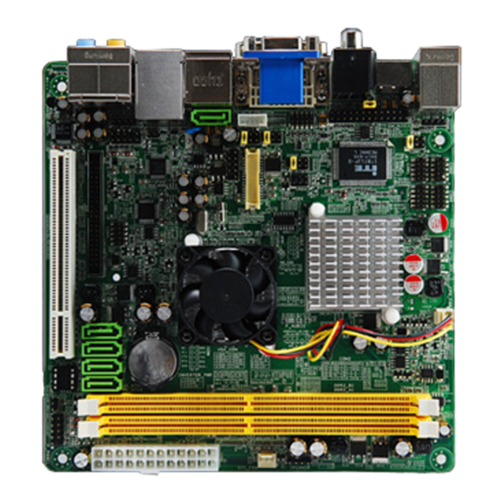
Mainboard Layou-Front
Mainboard Layou-Back
Chapter 2 Hardware Setup .................................................................................... 2-1
Memory .................................................................................................................
Power Supply ......................................................................................................
Back Panel I/O ......................................................................................................
Connector ............................................................................................................
Jumper .................................................................................................................
Slot .......................................................................................................................
Chapter 3 BIOS Setup ............................................................................................. 3-1
BIOS Setup .......................................................................................................... 3-2
Software Information ........................................................................................ 3-5
CONTENTS
...................................................................................... 1-5
......................................................................................
1-6
2-2
2-2
2-3
2-5
2-11
2-12
Advertisement
Table of Contents


Need help?
Do you have a question about the MCP7A ION and is the answer not in the manual?
Questions and answers