
Related Manuals for PEERLESS IWB600-WB


Summary of Contents for PEERLESS IWB600-WB
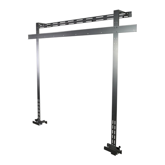
- Page 1 Installation and Assembly: Wall Mount for SMARTboard SB685/SB690 Model: IWB600-WB Max Load Capacity: 50 lb (22.6 kg) 1 of 7 ISSUED: 02-03-10 SHEET #: 125-9095-5 06-02-10...
- Page 2 PARTS LIST Description Qty. Part # A wall plate 095-4652 B upper cross support 095-4962 C support bracket 095-4667 D vertical support 095-4666 E rubber bumper 590-1159 F #10 washer 540-9442 G M4 x 6 mm phillips screw 520-2032 H #10-32 x 3/8 thumb screw 560-2107 knob 560-0223...
- Page 3 WARNING • Installer must verify that the supporting surface will safely support the combined load of the equipment and all attached hardware and components. NOTE: Make sure flange of wall bracket is located on top as shown in detail 1 Be sure wall bracket (A) is level and in desired position.
- Page 4 Secure Vertical brackets (D) to wall bracket (A) using two #10-32 x 3/8 thumb screws (H) and #10 flat washers (F). Detail 2 Secure SMARTboard channel to upper cross support (B) using eight M5 x 20 mm phillips screws (N) and eight M5 nylock nuts (L).
- Page 5 Secure upper cross support (B) to vertical supports (D) using four M4 x 8 mm phillips screws (M), and M4 nylock nuts (K). Detail 3 Hook SMARTboard into SMARTboard channel on upper cross support (B). SMARTboard channel SMARTboard Detail 4 SMARTboard channel 5 of 7...
- Page 6 Fasten two support brackets (C) to vertical supports (D) using four #10-32 x 3/8 thumb screws (H). Slide support brackets (C) up until bottom of SMARTboard rests on support as shown in detail 5. Tighten four #10-32 x 3/8 thumb screws (H). Detail 5 Fasten knob (I) through outside hole in support bracket (C) to determine rubber bumper (E) placement.
- Page 7 NOTE: Make sure mounting surface is suitable to hold the weight of the mount and smart board. Screws provided by installer 7 of 7 ISSUED: 02-03-10 SHEET #: 125-9095-5 06-02-10 © 2010, Peerless Industries, Inc. All rights reserved. All other brand and product names are trademarks or registered trademarks of their respective owners.
Need help?
Do you have a question about the IWB600-WB and is the answer not in the manual?
Questions and answers