Table of Contents
Advertisement
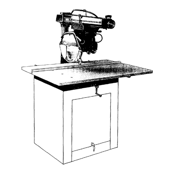
]Sears]
owners
manual
MODEL NO.
113.23301
Serial
Number
....
Model and serial
number may be found
at the left-hand side
of the base.
You should record both
model and serial number
in a safe place for
future use.
CAUTION:
Read
GENERAL
and
ADDITIONAL
SAFETY-
b:
INSTRUCTIONS
carefully
[RRFTSMRNo
12 INCH
RADIAL
SAW
• assembly
• operating
• repair
parts
Sold by SEARS,
ROEBUCK
AND
CO.,
Chicago,
IL. 60684
U.S.A.
Part No. 63568
Printed
ill U.S.A.
Advertisement
Table of Contents
Troubleshooting

Related Manuals for Craftsman 113.23301


Summary of Contents for Craftsman 113.23301
- Page 1 ]Sears] owners manual MODEL NO. 113.23301 Serial Number ..Model and serial number may be found at the left-hand side of the base. You should record both [RRFTSMRNo model and serial number in a safe place for future use. 12 INCH CAUTION: RADIAL Read...
- Page 2 FULL ONE YEAR WARRANTY ON CRAFTSMAN RADIAL SAWS If within one year from the date of purchase, this Craftsman Radial Saw fails due to a defect in material workmanship, Sears will repair it, free of charge. Warranty service is available...
- Page 3 additional safety instructions for radial saws -WARNING: ALLOW FAMILIARITY CAUTION: Always disconnect power cord before (GAINED FROM FREQUENT YOUR removing the guard, changing the cutting tool, changing the SAW) BECOME COMMONPLACE. ALWAYS set-up making adjustments. Shut motor before performing layout work on the saw table.
- Page 4 additional safety instructions for radial saws support _)_ guide the workpJece, to prevent rotating slippery, antikickback pawls stop twisting of the workpieee during operation. kickback. Never "RIP'" in the crosscut position. Never make a Therefore, rip with the firfished side down {next miter with...
-
Page 5: Table Of Contents
Unpacking and Checking Contents Key No. Before proceeding with the assembly of your (Fig. 2) Table Of Loose Parts Qty. Craftsman 12-Inch Radial saw, should read these instructions and follow them carefully. Table support (left-hand) ....This shipped complete carton. -
Page 6: Figure
assembly and adjustments BLOCK Figure LEFT-HAND TABLE SUPPORT SCREW x I IN.) 3/8-16 CARRIAGE STOP SCREW 14EX-L WRENCH _ .) 0/4 rNCH) LOCKWASHER FLAT WASHER (13/32 IN.) (3/8 In .) Figure Figure TABLE SUPPORf Mounting Your Saw Grasp the carriage with both hands... - Page 7 NO.2 CARRIAGE SUPPORT LOCK KNOB LATCH HAPJ BEVEL LOCK bASE Figure Figure MrTER SCALE INDICATOR CORD SCREW (No.6 32×7/i6 IN.PAN HD.) CLIP CARRIAGE ' dOVER I _1 RIP SCAL_ @_"_ IN DIC AT OR Figure Figure Install 2 table support (figure Lift latch...
- Page 8 assembly and adiustments Figure Figure ALIGNMENT INSTRUCTIONS Alignment instructions that follow are presented most logical order to insure accurate performance of your saw. WARNING: MAKE SURE POWER CORD IS NOT PLUGGED INTO ELECTRICAL OUTLET WHEN WORKING ON THE SAW. Removing Guard and Saw Blade Loosen guard...
- Page 9 Figure (LEFT Figure ABLE SUPPORT MOUNT until end of shaft is directly over the rear position moved from right to left, by hand, Also, make sure of table support 2. (See figure 18.) With the carriage lock knob (figure 16) is loose enough attaching screw hand...
-
Page 10: And Adjustments
assembly and adjustments LAICH HANDLE (K NOB) F LAT ,_/ASH ER (1/4 TABLE SLJPPORI LATCH "4 HANDLE (1/4 iN.) WASHE R.?'_ l I/4- 2O) BEVEL LOCK KNOB Figure Figure Figure IFI[S HOLE USED TABLE _NSTALLAItON '€,'RE NC h Figure Figure nuts on all screws except the one that threads... - Page 11 2_RM [&ECH klAN LATCH HANDLE BEvEl lOCK _rdO_ Figure 28 Figure MJTER SCA[E ZHNG SCREWS Figure Figure Figure Rotate latch handle (knob) turn the square at all positions. If saw tooth "A" does counterclockwise. (See figure 28.) Make sure the touch square points,...
- Page 12 assembly and adjustments EV¢Iv_E[ L_TDH K_OB YOKE CLAMP HANDLE CARRIAGE LOCK KNOB TABLE SPACER "rOKE Figure Figure rE_< C,\RRbXGE LOCK KNOB REAR FENCE NEARESJ" BLADE TOOTH MEAS:JRE FROM m/ X-..." FRONT ";ABLE © PENCE REAR fABLE TABLE SPACER BOARD Figure Figure Figure 39 Installing...
-
Page 13: Connections
fence should be at extreme rear blade sawblade (perpendicular plane sawblade): positioned as shown in figure 39. With 12 inches measured between fence (when in full rear When in the cut (Guards in full down position position) face blade, rip-scale (Touching table) carriage... - Page 14 electrical connections WARNING: PERMIT FINGERS This tool should be grounded while in use to protect CONTACT TERMINALS operator from electrical shock. POWER MOTOR PLUGS WHEN INSTALLING OR REMOVING PLUG MOTOR SAFETY PROTECTION FROM A LIVE POWER SOURCE. (SEE FIGURE 43.) saw motor is equipped with...
-
Page 15: Switch Key
operating controls DEPIH ,_NGLE _ARRIAS[ L()1:_ 1 Arm Latch Lever 1 1. Bevel Index Scale 12. Bevel Lock Knob 2. Swivel Lalch Pin Knob 13. Anti-Kickback 3, Rip Scale Indicator Spreader BLADE ANI;LE Assembly 4 Radia_ Arm Indicator 14. Bevel Index Handle 5. - Page 16 operating controls W'NG SCREV_ LOWER OUTER LOWER NNER GUARD GUARD OUTSIDE iNS1 lie VIEW VIEW ARtd_ LATCH HANDLL Figure Figure pull out the arm latch lever (1) and move the blade angle are: bevel lock knob (12, figure radial arm off the index position.
- Page 17 PRECISION INDEXING follows: Experienced operators of precision equipment, such as this Position the saw blade the proper distance from Craftsman Radial Saw, normally acquire habit the fence to produce the desired width of the rip indexing machine direction only, whenever cut.
- Page 18 basic saw operations BASIC OPERATIONS REQUIREMENTS FOR CROSSCUT Yok_r Craftsma_ 12inch Radial extremely versatile tool, capable of performing innumerable cuts with (OPERATIONS 1 THROUGH sufficient accuracy to satisfy both amateur and professional wood-working requirements, Basic operations ArboP must be tight and saw blade guard installed...
- Page 19 Provide a straight edge, even if this means temporary desired angle of cut; yoke and bevel settings indexed at 0 ° nailing auxiliary straight-edged board (and locked) as in square crosscutting. The board being cut is hetd firmly against fence carriage pulled work.
- Page 20 basic saw operations SWIVEL LATCH KNOB ARM LATCH HANDLE Out-Ripping (See figure 58.) The radial arm and bevel are indexed at 0 ° and locked, but the yoke is turned 90-degrees in a counterclockwise direction (viewed from above), from the crosscut position.
- Page 21 Craftsman Conversely, loosening right-hand set screw saw, it is reasonable to expect some wear after long periods tightening left-hand screw, will of use. Adjustment...
- Page 22 trouble shooting Bearings Loose on Tracks. Adjust carriage bearings as described in subsequent instructions. Yoke Does Not Index Properly. Check proper yoke indexing noting that the swivel latch fits into its detents properly. swivel latch housing screws (located under left-hand carriage cover) are loose,...
- Page 23 ATTACHNG CARRIAGE SCREWS COVER {LEFT-HAND) lEVEL iNDEX SCALE SOCKE_{ _,OR SCREV, IFOUR TOIAL) BEVEL LOCK KNOB Figure Figure 67 ECCENTRIC ECCENTRIC SCREW SCREW YOKE CLAMP ASSEMBLY. BEARING Figure Figure Figure If the saw blade is square with the table top, necessary perform several...
- Page 24 trouble shooting Figure 72 YOKE CLAMP ASSEMBLY Yoke Clamp Handle Adjustment. normal locking position of the yoke clamp handle (figure approximately midway between sides yoke. When sufficient wear has occured to permit the handle move considerably rear, strike yoke before locking, the handle be adjusted...
- Page 25 Crosscutting Heeling right will tend to slide workpiece toward right along fence, as the cut is being made, and make a square cut almost impossible. HEX HEAD SCREWS-- Heeling to the left will tend to slide the board to the left along the fence.
- Page 26 trouble shooting Make sure teeth ANTIKtCKBACK pawls always sharp. Replace if not sharp. TROUBLE SHOOTING CHART NOTE: Motors used on wood-working tools are particularly should be blown out or "vacuumed'" frequently susceptible to the accumulation of sawdust and wood chips prevent interference with normal motor ventilation.
- Page 27 TROUBLE SHOOTING CHART (Con't.) TROUBLE PROBABLE CAUSE REMEDY Motor stalls (resulting 1. Starting relay not operating. 1. Replace relay. blown fuses or tripped 2. Voltage too low to permit 2, Correct the low line voltage condition. circuit breakers). motor to reach operating speed 3, Fuses or circuit breakers...
- Page 28 CRAFTSMAN 12-INCH RADIAL SAW, MODEL N0. 113,23301 <7 "'l "0 Figure...
- Page 29 PARTS LIST CRAFTSMAN 12-INCH RADIAL SAW, MODEL No. 113.23301 parts illustrated in Figures 1 through 6 and listed under part numbers be ordered through any Sears retail store or Catalog order store. Order parts by mail from the Catalog order...
- Page 30 CRAFTSMAN 12-INCH RADIAL SAW, MODEL No. 113.23301 • FIGURE 2 PARTS LIST "1 "O Part Description 63119 Retainer, Spring .ii.. 60040 Washer, 21/64 x 3/4 x 1/16 STD 551131 * Lockwasher, 5/16 STD 523115 *Screw, Mach.,5/16-18 x 1-1/2,Hex.Hd. 62332 Knob...
- Page 31 CRAFTSMAN 12-INCH RADIAL SAW, MODEL No. 113.23301 Figure FIGURE 3 PARTS LIST- 63496 GUARD ASSEMBLY Part Part Description Description 63496 STD 60110E Guard Assembly (Complete) *Screw, No. 10-32 x 7/16, 1 STD 522507 *Screw, Hex. Hd., 1/4-20 x 3/4 Type 23, Pan Hd.
- Page 32 CRAFTSMAN "I2-1NCH RADIAL SAW, MODEL No. 113.23301 i/37 Figure 4...
- Page 33 CRAFTSMAN 12-INCH RADIAL SAW, MODEL No. 113.23301 FIGURE 4 PARTS LIST Part Part Description Description STD 503105 *Screw, Set, 5/16-18 x 1/2,Slotted,Cup STD 541025 *Nut, Hex., 1/4-20 63078 Plug, Back Up (Steel) 30505 *Wrench, Hex."L", 1/8 Across Flals 63077 STD 502503...
- Page 34 CRAFTSMAN 12-INCH RADIAL SAW, MODEL No. 113.23301 • "O .._ ® ATTEMPT REPAIR THIS MOTOR CREATE 13 8 Figure 5 HAZARD UNLESS REPAIR DONE QUALIFfED SERVICE TECHNICIAN. REPAIR SERVICE IS AVAILABLE AT YOUR NEAREST SEARS STORE. FIGURE 5 PARTS LIST - 63494 MOTOR...
- Page 35 CRAFTSMAN 12-INCH RADIAL SAW, MODEL No. 113.23301 12-_ Figure FIGURE 6 PARTS LIST Part Part Description Description 30547 D isk 63549 Switch Plate 30548 Spring, Latch 37935 Washer, Fibre, 9/64 x 1/4 x 1/32 30689 Pin, Bevel Latch 63423 Indicator, No.
- Page 36 [Sears ! owners 12 INCH RADIAL SAW manual SERVICE Now that you have purchased your 12 inch radial saw, should a need ever exist for repair parts or service, simply contact Sears Service Center and most Sears, Roebuck and Co. stores. Be sure to provide all pertinent facts when you call or visit.
Need help?
Do you have a question about the 113.23301 and is the answer not in the manual?
Questions and answers