Table of Contents
Advertisement
_F
Save
This Manual
or Future Reference
owner's
manual
MODEL NO.
113.234610
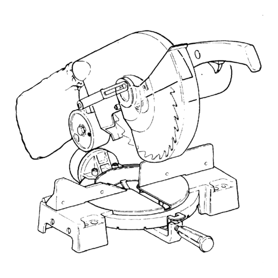
10" COMPOUND
MITER SAW
Serial
Number
Model and serial numbers
may be found at the side of
the miter saw arm.
You should record both
model
and serial number in
a safe place for future use.
CAUTION:
READ ALL
INSTRUCTIONS
CAREFULLY
CRRFTSMRN
IO-INCH COMPOUND
MITER SAW
• assembly
• operating
• repair parts
Sold by SEARS, ROEBUCK AND CO., Chicago,
IL 60684
U.S.A.
Part No. SP5092
J
Advertisement
Table of Contents

Related Manuals for Craftsman 113.234610


Summary of Contents for Craftsman 113.234610
- Page 1 Save This Manual or Future Reference owner's manual MODEL NO. 113.234610 10" COMPOUND MITER SAW Serial Number Model and serial numbers may be found at the side of the miter saw arm. CRRFTSMRN You should record both model and serial number in a safe place for future use.
-
Page 2: General Safety Instructions
FULL ONE YEAR WARRANTY ON CRAFTSMAN MITER SAW If within one year from the date of purchase, this Craftsman Miter Saw fails due to a defect in material or workmanship, Sears will repair it, free of charge. WARRANTY SERVICE IS AVAILABLE... -
Page 3: Using The Saw
additional safety instructions for miter saw Safety is a combination of common sense, staying alert power tool can result in foreign objects being and knowing how your miter saw works thrown into the eyes, which can result in perma- _,.o'- nent eye damage. -
Page 4: Whenever Saw Is Running
10. Never out more than one workpiece at a time. f. To avoid injury from accidental starting, always unplug saw before disconnecting the guard, 11. Make sure the cut off piece can move side- stalling or removing any blade, accessory ways after it's cut off. -
Page 5: Electrical Connections
Revolutions Per Minute (RPM) Workpiece The number of turns completed by a spinning object The item on which the cutting operation is being per- one minute. formed. The surfaces of a workpiece are commonly referred to as faces, ends, and edges. Sawblade Path The area of the workpiece... -
Page 6: Wire Sizes
the load and the supply circuit whenever motor For orcuits that are farther than 100 feet away from electrical service box, the w_re s_ze must be increased doesn't work well. Check wire sizes and length with the Wire Size Chart below, proportionately in order to deliver ample voltage to the saw motor. -
Page 7: Tools Needed
tools needed COMBINATION SQUARE MUST BE TRUE Tools required for assembly and alignment: • Medium Screwdriver DRAW LIGHT STRAIGHT EDGE OF • #2 Phillips Screwdriver LINE ON BOARD BOARD 3/4" THICK • Combination Square ALONG THIS EDGE,_ _,.A , THIS EDGE MUST BE "_--"... -
Page 8: Knowing Your Miter Saw
knowing your miter saw WARNING LABEL 1, Warning label. 2. Handle Latch--The miter saw can be locked in the lowered position for compact storage, 3. Fence Lock Handles--The fence has two positions for increased crosscut capacity. The lock handles secure the fence to the base. The saw is shipped HANDLE LATCH with the fence in the front position. -
Page 9: Assembly And Alignment
assembly and alignment HANDLE ASSEMBLY ALIGNMENT LATCH Assembling the Lower Blade Guard NOTE: For compact shipment the lower blade guard has been partially disconnected. 1. The miter saw is equipped with a handle latch used to lock the miter saw in the lowered position release, push the handle down slightly... - Page 10 Step Two--Checking and Aligning Blade with Turn Table Slot 1 The blade should look like it's parallel to the sides of the turn table slot. The blade should be 1/8"closer to left side than right, 2. If blade looks parallel with turn table slot proceed to step three.
- Page 11 Step Four--Pivot Adjustments PIVOT BOLT NOTE: These adjustments were made at the factory and normally do not require readjustment, 1. The miter saw should rise completely to the up posi- tion by itself, If the saw will not raise by itself or if there is play in the pivot joints the following adjust- ments are necessary.
- Page 12 FencePositions miter saw has two fence positions. The front fence position is used for workpieces up to standard 2 x 4 for cut off and bevel operation, floor and ceiling moldings, and door casings. The rear fence position is used for cut off and bevel operation for a standard 2 x 6 workpiece.
-
Page 13: Mounting The Saw
NOTE: Pay attention to pieces removed, noting, their ARBOR BLADE position and direction they face (see illustration). Wipe WASHER the blade collars clean of any sawdust before installing the new blades. 8. Install the new 10" blade (see recommended acces- sory list) Make sure the rotation arrow on the blade matches... - Page 14 If the saw is to be used in a portable application, mount the saw to a 3/4"piece of plywood. The mounting board can then be clamped down to prevent it from tipping. MOUNTING BOLTS MOUNTING BOARD CATALOG 3/4" PLYWOOD NO. 9-22244 NOTE: Attach the mounting board to the leg set first.
-
Page 15: Basic Saw Operations
10" Attach mounting board to holes indicated. FRONT SIDE CATALOG NO. 9-22244 LEG SET BASIC OPERATIONS WARNING: FOR YOUR OWN SAFETY, READ AND • DO NOT CUT METAL WORKPIECES THAT UNDERSTAND ALL SAFETY INSTRUCTIONS MUST BE HAND HELD: AUXILIARY OPERATING PROCEDURES THROUGHOUT CLAMPS... - Page 16 7. Never c ut FREEHAND: 13, Never turn your miter saw "ON" before clearing a. Braceyourworkpiece s olidlyagainst t hefence everything except the workpiece and related sup- port devices off the table. andtabletop so it will notrockor twistduring the cut.Makesurethereis no debriscaught 14.
- Page 17 MiterCut Whena miter cut is required, move the saw to the desired angle. Do not stand in front of the saw table. Move with the handle to the miter angle to make the cut. NOTE: Remember to loosen the fence lock handles before changing the miter angle with the fence in the rear position.
- Page 18 Compound When a compound cut is required, select the correct bevel and miter position. Move with the handle to the miter angle to make the cut. If the fence is in the rear position, loosen the two lock handles before changing the miter angle.
- Page 19 Workpiece Support Long pieces need extra supports. The supports should be placed along the workpiece so the workpiece does _not sag and your hand holding the workpiece positioned 4" or more from the blade path. The support should let the workpiece lay flat on the base and work table during the cutting operation.
- Page 20 Filler Blocks for Cutting Crown Moldings placed on the table upside down. The majority of crown moldings have contact surfaces When the filler blocks are attached to the fence with of 52 ° and 38 ° to the rear surface of the molding, When the face of the filler blocks pointing downwards, joining the face of the filler block these angles must be molding must be placed on the table right side up.
-
Page 21: Maintenance And Lubrication
maintenance and lubrication Maintenance WARNING: IF BLOWING SAWDUST, WEAR PROPER Always unplug the power cord before any maintenance EYE PROTECTION TO KEEP DEBRIS FROM BLOW- check on this saw ING INTO EYES. Recommended Accessories DANGER: Never put lubricants on the blade while it's spinning, WARNING:... -
Page 22: Trouble Shooting
TROUBLE SHOOTING GUIDE - MOTOR PROBLEM PROBABLE CAUSE SUGGESTED CORRECTIVE ACTION Brake does not stop Brushes not seated --Inspect/clean/replace brushes blade within or lightly sticking, (see maintenance section). 2-3 seconds. --Use a recommended blade Motor brake winding- overheated from use of not- --Let cool down. - Page 23 BRUSH SHORT BLUE WHITE LONG IJ" BLUE 1/" BLACK GRAY TRIGGER BRAKE SWITCH BRUSH CIRCUIT DIAGRAM NOTES...
- Page 24 PARTS LIST FOR CRAFTSMAN 10" COMPOUND MITER SAW MODEL NO. 113.234610...
-
Page 25: Repair Parts
PARTS LIST FOR CRAFTSMAN 10" COMPOUND MITER SAW MODEL NO. 113.234610 Always order by Part Number--Not by Key Number FIGURE Part Part Description Description 8 t 6685 Arm-Miter Blade Guard Asm. 816669 Handle-Miter (see Fig. 4) STD523108 *Bolt-Hex HD. 5/16-18 x 7/8 Motor Asm. - Page 26 PARTS LIST FOR CRAFTSMAN 10" COMPOUND MITER SAW MODEL NO. 113.23461,0 '°'I Always order by Part Number--Not by Key Number FIGURE 2--ARM AND MOTOR ASSEMBLY WARNING: For your safety, this miter saw is specially insulated. To avoid electrical shock, fire or injury, use only parts identical to those identified in the parts list.
- Page 27 PARTS LIST FOR CRAFTSMAN 10" COMPOUND MITER SAW MODEL NO. 113.234610 Always order by Part Number--Not by Key Number FIGURE 3--PIVOT ASSEMBLY Part Description Part Description 816664 Plate-Lock 60032 Screw Soc HD, Cap 3/8-16 816674 Screw Pan HD, Shoulder M6...
- Page 28 PARTS LIST FOR CRAFTSMAN 10" COMPOUND MITER SAW MODEL NO. 113.234610...
- Page 29 PARTS LIST FOR CRAFTSMAN 10" COMPOUND MITER SAW MODEL NO, 113.234610 Always order by Part Number--Not by Key Number FIGURE 4. Blade & Blade Guard Asm.¢ Part Description Part Description IIIIIII 816703 Scr. Hex Washer HD. Guard Asm 507758 L.H M8 x 1.25...
- Page 30 NOTES...
- Page 31 NOTES...
-
Page 32: How To Order Repair Parts
owner's 10-1NCH COMPOUND manual MITER SAW Now that you have purchased your 10-inch Compound Miter SERVICE Saw, should a need ever exist for repair parts or service, simply contact Sears Service Center most Sears, Roebuck Co. store_ Be sure to provide all pertinent facts when you call or visit...
Need help?
Do you have a question about the 113.234610 and is the answer not in the manual?
Questions and answers