Table of Contents
Advertisement
Available languages
Available languages
Owner's Manual/Manual
Del Propietario
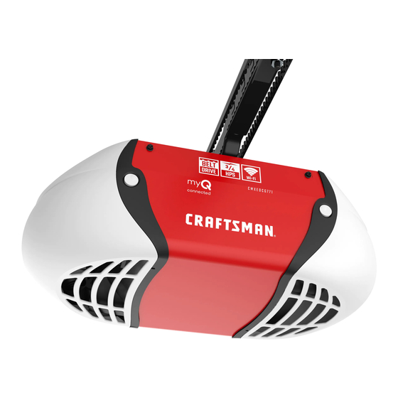
I CRRFTSMI:INI
314 HP
GARAGE
DOOR OPENER
ABRIDOR
DE PUERTA DE COCHERA
For Residential
Use Only/Solo
para uso residencial
Models/Modelos
139.53924
m
Z
G3
m
I"11
Z_
C3
Read and follow all safety rules
and operating
instructions
before
first use of this product.
Fasten the manual near the garage
door after installation.
Periodic checks of the opener are
required to ensure safe operation.
Leer y seguir todas las reglas de
seguridad
y las instrucciones
de
operacion
antes de usar este
producto por primera vez.
Guardar este manual cerca de la
puerta de la cochera.
Se deben realizar revisiones
periodicas
del abridor de puertas
para asegurar su operacion
segura.
Sears,
Roebuck
and Co., Hoffman
Estates,
IL 60179
U.S.A
www.sears.com/craftsman
Advertisement
Chapters
Table of Contents

Related Manuals for Craftsman 139.53924


Summary of Contents for Craftsman 139.53924
- Page 1 Se deben realizar revisiones Periodic checks of the opener are periodicas del abridor de puertas required to ensure safe operation. para asegurar su operacion segura. Sears, Roebuck and Co., Hoffman Estates, IL 60179 U.S.A www.sears.com/craftsman...
-
Page 2: Table Of Contents
TABLE OF CONTENTS Introduction 2- 7 Adjustment Section 27-29 Safety symbol and signal word review ......2 Adjust the travel limits ..........Preparing your garage door ........Adjust the force ............Tools needed ............... Test the safety reversing sensor ....... 29 Planning .............. -
Page 3: Preparing Your Garage Door
Preparing your garage door Before you begin: To prevent possible SERIOUSINJURYor DEATH: • Disable locks. • ALWAYScall a trained door systems technician if • Remove any ropes connected to garage door. garage door binds, sticks, or is out of balance. An unbalancedgarage door may not reverse when •... -
Page 4: Planning
Planning Identify the type and height of your garage door. Do you have an access door in addition to the Survey your garage area to see if any of the garage door? If not, Model 53702 Emergency Key conditions below apply to your installation. Additional Release is required. - Page 5 Planning (Continued) ONE-PIECE DOOR INSTALLATIONS Without a properly working safety reversal system, persons (particularly small children) could be • Generally, a one-piece door does not require SERIOUSLYINJUREDor KILLED by a closing garage reinforcement. If your door is lightweight, refer to door.
-
Page 6: Carton Inventory
Carton Inventory Your garage door opener is packaged in one carton packing material. Hardware for assembly and which contains the motor unit and all parts illustrated installation is shown on the next page. Save the below. Accessories will depend on the model carton and packing material until installation and purchased. -
Page 7: Hardware Inventory
Hardware Inventory Separate all hardware and group as shown below for the assembly and installation procedures. ASSEMBLY HARDWARE Bolt Hex Bolt Lock Nut 1/4-20xl-3/4" 1/4'L20x5/8" 1/4'L20x7/16 (12) Sprocket Coupling Sleeve INSTALLATION HARDWARE Carriage Bolt Wing Nut Ring Nut 5/16"-18 (6) Handle 1/4'L20x1/2 '' (2) 1/4'L20 (2) -
Page 8: Assemble The Rail
ASSEMBLY STEP Assemble Rail To prevent INJURYfrom pinching, keep hands and fingers away from the joints while assembling the rail. To avoid installation difficulties, do not run the garage door opener until instructed to do so. 1. Turn the opened rail carton upside down and empty its contents onto a level work surface. - Page 9 Assemble Rail (Continued) 4. Beginning with the sprocket end, straighten the three rail sections so that the screw rod is in a straight line at the joints. (Avoid handling the joints, which may have sharp edges.) 5. Carefully slide the pins at the top edge of the rail into the openings on the adjacent rail.
- Page 10 ASSEMBLY STEP Fasten the Rail To the Motor Unit Install Trolley • Working on a level surface, align the rail assembly with the motor unit, as shown. • Slip the coupling over the rail sprocket. • Slide the rail through the motor unit bracket until the coupling fits securely over the motor unit HARDWARE SHOWN ACTUAL...
-
Page 11: Attach Rail Brackets
Lock Nuts ASSEMBLY STEP 1/4"-20 Rail Attach the Rail Brackets Brackets • Align rail brackets to end of rail assembly, as shown. • Insert two 1/4"-20 x 5/8" hex bolts and lock nuts. Tighten securely with a 7/16" socket. Hex Bolts 1/4"-20x5/8 Rail You have now finished assembfing your garage... -
Page 12: Determine The Header Bracket Location
INSTALLATION STEP OPTIONAL CEILING Determine Header Bracket MOUNT Location HEADER Unllnigh_ BRACKET Header Wall Vertical Centerline of Garage Door To prevent possible SERIOUSINJURYor DEATH: • Headerbracket MUST be RIGIDLYfastenedto Structural Supports structural support on header wall or ceiling, otherwise garage door might not reverse when required. DO NOT install header bracket over drywall. -
Page 13: Install The Header Bracket
INSTALLATION STEP Install Header Bracket Wall Mounting Holes You can attach the header bracket either to the wall above the garage door, or to the ceiling. Follow the The nail hole is for instructions which will work best for your particular You must use lag screws requirements. -
Page 14: Attach The Rail To The Header Bracket
INSTALLATION STEP Attach the Rail to the Header Bracket • Position the opener on the garage floor below the header bracket. Use packing material as a protective base. NOTE: If the door spring is in the way you'll need help. Have someone hold the opener securely on a temporary support to allow the rail to clear the spring. -
Page 15: Install The Protector System
INSTALLATION STEP Install The Protector System ® • Be sure power is not connectedto the garage door opener BEFORE installing the safety reversing sensor The safety reversing sensor must be connected • To prevent SERIOUSINJURYor DEATHfrom a closing and aligned correctly before the garage door garage door: opener will move in the down direction. - Page 16 INSTALLING THE BRACKETS Be sure power to the opener is disconnected. Figure 1 DOOR TRACK MOUNT Install and align the brackets so the sensors will face RIGHT SIDE) each other across the garage door, with the beam no higher than 6" (15 cm) above the floor. They may be Door installed in one of three ways, as follows.
- Page 17 MOUNTING A ND WIRING THE SAFETY SENSORS Figure 5 • Slide a 1/4"-20xl/2" carriage bolt head into the slot on each sensor. Use wing nuts to fasten sensors to brackets, with lenses pointing toward each other across the door. Be sure the lens is not obstructed by a bracket extension (see Figure 5).
-
Page 18: Position The Opener
INSTALLATION STEP Position Opener To prevent damageto garage door, rest garage door opener rail on 2x4 placed on top section of door. Follow instructions which apply to your door type as illustrated. SECTIONAL DOOR OR ONE-PIECE DOOR WITH TRACK A 2x4 laid flat is convenient for setting an ideal door-to-rail distance. -
Page 19: Hang The Opener
INSTALLATION STEP Hang Opener To avoid possible SERIOUSINJURYfrom a falling garage door opener,fasten it SECURELY to structural Three representative installations are shown. Yours supports of the garage. Concrete anchors MUST be used may be different. Hanging brackets should be angled if installing any brackets into masonry. - Page 20 INSTALLATION STEP Install Door Control To prevent possible SERIOUSINJURYor DEATHfrom electrocution: Locate door control within sight of door, at a • Be sure power is not connected BEFORE installing door minimum height of 5 feet (1.52 m) where small control. children cannot reach, away from moving parts of •...
-
Page 21: Electrical Requirements
INSTALLATION STEP Electrical Requirements To prevent possible SERIOUSINJURYor DEATHfrom electrocution or fire: To avoid installation difficulties, do not run the • Be sure power is not connected to the opener,and opener at this time. disconnect power to circuit BEFORE removing cover to To reduce the risk of electric shock, your garage door establish permanent wiring connection. -
Page 22: Install The Lights
INSTALLATION STEP Install Lights To prevent possible OVERHEATING of the endpanel or light socket: • Press the release tabs on both sides of lens. • DO NOT use short neck or specialty light bulbs. Gently rotate lens back and downward until the •... -
Page 23: Fasten The Door Bracket
INSTALLATION STEP Fasten Door Bracket Fiberglass, aluminum or lightweight steel garage doors WILL REQUIREreinforcement BEFORE installation of Follow instructions which apply to your door type door bracket. Contact your door manufacturer for as illustrated below or on the following page. reinforcement kit. - Page 24 ONE-PIECE D OORS Please read and comply with the warnings and reinforcement instructions on the previous page. They apply to one-piece doors also. • Center the door bracket on the top of the door, in line with the header bracket as shown. Mark either the left and right, or the top and bottom holes.
-
Page 25: Connect Door Arm To Trolley
INSTALLATION STEP inner Outer Trolley Trolley Connect Door to Trolley Follow instructions which apply to your door type as illustrated below and on the following page. SECTIONAL DOORS ONLY Clevis Pin 5/16"x1" • Make sure garage door is fully closed. Pull the emergency release handle to disconnect the outer trolley from the inner trolley. - Page 26 ALL ONE-PIECE DOORS Door 1.Assemble the door arm, Figure 4: Bracket _t_..,.,.,_ Ring • Fasten the straight and curved door arm sections Lock 5/16"-18 together to the longest possible length (with a 2 Washers 5/16" I _ I or 3 hole overlap). 5/1Clevis Pin6,,x1-1/4"...
- Page 27 ADJUSTMENT STEP Adjust UP and DOWN Travel Without a properly installed safety reversal system, Limits persons (particularly small children) could be SERIOUSLYINJUREDor KILLED by a closing garage Limit adjustment settings regulate the points at which door. the door will stop when moving up or down. •...
-
Page 28: Adjust The Force
ADJUSTMENT STEP Adjust Force Without a properly installed safety reversal system, persons (particularly small children) could be Force adjustment controls are located on the left SERIOUSLY INJURED or KILLED by a closing garage panel of the motor unit. Force adjustment settings door. -
Page 29: Test The Protector System
ADJUSTMENT STEP Test the Safety Reversal System Without a properly installed safety reversal system, persons (particularly small children) could be TEST SERIOUSLY INJUREDor KILLED by a closing garage door. • With the door fully open, place a 1-1/2" (3.8 cm) •... -
Page 30: Operation
OPERATION IMPORTANT SAFETY INSTRUCTIONS To reduce the risk of severe injury or death: 1. READAND FOLLOWALL WARNINGSAND 9. If one control (force or travel limits) is adjusted, the INSTRUCTIONS. other control may also need adjustment. 2. ALWAYSkeep remote controls out of reach of children. 10. -
Page 31: Using The Wall-Mounted Door Control
Additional feature when used with the 3-Function Using Wall.Mounted hand-heM remote Door Control To control the opener lights: THE MOTION DETECTING CONTROL CONSOLE In addition to operating the door, you may program the remote to operate Press the lighted push button to the lights. -
Page 32: To Open The Door Manually
To Open the Door Manually CARE OF YOUR OPENER LIMIT AND FORCE ADJUSTMENTS: Weather conditions may cause FORCE CONTROLS To prevent possible SERIOUSINJURYor DEATHfrom a some minor changes in door falling garage door: operation requiring some re- • If possible, use emergency releasehandle to adjustments, particularly during disengagetrolley ONLYwhen garage door is the first year of operation. -
Page 33: Havinga Problem
HAVING A PROBLEM? 1. My door will not close and the light bulbs blink on my motor unit: The safety reversing sensor must be connected and aligned correctly before the garage door opener will move in the down direction. • Verify the safety sensors are properly installed, aligned and free of any obstructions. -
Page 34: Diagnostic Chart
Your garage door opener is programmed with self-diagnostic capabilities. The "Learn" button/diagnostic LED will flash a number of times then pause signifying it has found a potential issue. Consult Diagnostic Chart below. Diagnostic Chart Symptom: One or both of the Indicator lights on the safety sensors do not glow steady. -
Page 35: Programming
PROGRAMMING NOTICE: If this Security+_ garage door opener is operated with a non-rolling code transmitter, the technical measure in the receiver of the garage door opener, which provides security against code-theft devices, will be circumvented. The owner of the copyright in the garage door opener does not authorize the purchaser or supplier of the non-rolling code transmitter to circumvent that technical measure, Your garage door opener has already been programmed at the factory to operate with your hand-held remote control, The door will open and close when you press the large push button,... - Page 36 To Add, Reprogram or Change a Keyless Entry NOTE: Your new Keyless Entry must be programmed to operate your garage door opener. USING THE "LEARN" BUTTON USING THE MOTION DETECTING CONTROL CONSOLE 1. Press and release the "learn" NOTE: This method requires two people ff the Keyless button on motor unit.
-
Page 37: Repair Parts
REPAIR PARTS Rail Assembly Parts PART DESCRIPTION 41A4796 Hardware bag 41A4795 Hardware bag (includes sprocket coupling) 12B569-1 Left rail bracket 12B569-2 Right rail bracket 1C4827-1 Screw drive rail assembly 12B560M Rail support braces (4) 81C168 Rack 41C4677 Complete trolley assembly 25C20 Sprocket coupling 41A4836... -
Page 38: Motor Unit Assembly Parts
Motor Unit Assembly Parts 3b Z (Down) LIMIT SWITCH Brown Contact ASSE_dIBLY Wire Wire Gear Center Limit (Up) Yellow Contact Contact Wire PART PART DESCRIPTION DESCRIPTION 31 C545 Drive shaft cover 41 C4672 Screw drive RPM kit 41 B4245 Line cord 41A4837-1 Worm gear and retainer 30B530... -
Page 39: Function Remote Control
ACCESSORIES SECURITY+ 3-Function Remote 139.53702 139.53681 Emergency Key Release: Control: Required for a garage with NO access door. Enables homeowner Includes visor clip. to open garage door manually from outside by disengaging trolley. 139.53404 8 Foot Rail Extension: 139.53680 SECURITY+ Compact To allow an 8 foot door to open 3-Function Remote Control:... - Page 40 CONTENIDO Introducci6n Ajustes 27.29 Revisi6n de los simbolos y t@minos de seguridad ....2 Ajuste el limite del recorrido ..........Preparaci6n de la puerta de su cochera ......3 Ajuste la fuerza ..............Herramientas necesarias ............Pruebe el sistema de retroceso de seguridad ....29 Planificaci6n ..............
-
Page 41: Preparaci6N De La Puerta De Su Cochera
Preparaci6n de la puerta su cochera Para evitar una LESIONGRAVEo INCLUSOLA MUERTE: Antes de comenzar: • SIEMPREIlame a un t_cnico profesional para que le d_ • Quite los seguros. servicio a su puerta de cochera si 6sta se atora, se pandea o •... -
Page 42: Planificaci6N
Planificaci6n &Hay otra puerta que de acceso a la cochera? Si no es as[, sera necesario contar con el sistema de Ilave de Identifique la altura y el tipo de su puerta de cochera. emergencia Modelo 53702. Vea la p_.gina de Accesorios. Revise el Area de su cochera y observe si alguna de Observe el punto donde la puerta hace contacto con el las siguientes instalaciones corresponden... - Page 43 Planificaci6n (continba) INSTALACION CON PUERTAS DE UNA SOLA PIEZA Sin un sistemaderetrocesode seguridadquefuncione debidamente, al cerrar la puerta de la cochera se corre el • Generalmente una puerta de una sola pieza no requiere riesgo de que las personas (y en particular los nifios refuerzos adicionales Si usted tiene una puerta de peque5os) sufran LESIONESGRAVESo INCLUSOLA MUERTE.
-
Page 44: Inventario De Las Cajas De Cart6N
Inventario de las Cajas de Cart6n Su abridor viene empacado en una caja de carton que Toda la tornilleria y las piezas necesarias para el montaje e contiene el motor y las piezas que se muestran en la instalaci6n de su puerta se ilustran en la siguiente pagina. siguiente ilustracion. -
Page 45: Inventario De Piezas
Inventario de Piezas Antes de la instalaci6n, organice todas las piezas en grupos come se muestra en la siguiente ilustracion. TORNILLER|A Y PIEZAS PARA EL MONTAJE Pemode Pemo hexagonaE Tuercade 1/4-20xl-3/4 pulg, (8) de 1/4-20x5/8 pulg. (4) 1/4-20x7/16pulg, (12) Manguitodel copb de la poba TORNILLER|A Y PIEZAS PARA LA INSTALACION ©... -
Page 46: Montaje
MONTAJE, PASO Montaje riel ParaevitarQUESEPELLIZQUE, conserve los manosy dedos lejosde lasjuntascuandomonteel reil. No encienda ni use el abridor hasta que Ilegue al paso de la instalacion correspondiente, de otra manera corre el riesgo de complicar el proceso de instalacion. 1. Despues de abrir la caja del riel, p6ngala boca abajo sobre una superficie de trabajo plana. - Page 47 Montaje del riel (Continuaci6n) 4. Empezando en el extreme con la rueda dentada, coloque las tres secciones del riel de manera que la varilla de conexion este alineada. (Tenga cuidado de no tocar el extremo de la varilla de conexi6n ya que tiene orillas afiladas.) 5.
- Page 48 MONTAJE, PASO Fije el riel a la unidad del motor instale el trole • Sobre una superficie plana, alinee el riel ya armado al motor como se muestra en la siguiente ilustracion • Deslice el cople sobre la polea del riel •...
-
Page 49: Coloque Las Mensulas Del Riel
Tuercasde 1/4-20 pulg. Soportes MONTAJE, PASO del riel Coloque m6nsulas del riel • Alinee las mensulas con la parte trasera del riel como se muestra. • Atornille las mensulas con los pernos hexagonales de 1/4-20x5/8 y las tuercas respectivas. Apriete firmemente con una Ilave de 7/16 pulg. -
Page 50: Determine D6Nde Va A Instalar La M6Nsula Del Cabezal
I NSTALACI ON, PASO InSTaLaCJ0n oPclonAL LA MSNSULA DEL CABEZAL Determine dOnde va a instalar EN EL CIELO RASO la MOnsula Cabezal CMo raso sin acabado Pared Para evitar una posible LESIONGRAVEo INCLUSOLA MUERTE: delantera • La mOnsuladel cabezal DEBEquedar RJGIDAMENTE sujeta Linea central al soporte estructural en la pared delantera o en el cielo vertical de la... -
Page 51: Instale La M6Nsula Del Cabezal
INSTALACION, PASO Orificiospara la instalaci6n de pared Instale la M6nsula del Cabezal Este orificio es solamente para marcar la posici6nde La mensula del cabezal se puede fijar a la pared justo por la mensula. Se deben de utilizar los tornillosde cabeza encima de la puerta de la cochera o en el cielo raso. -
Page 52: Coloque El Riel En La M6Nsula Del Cabezal
INSTALACION, PASO Coloque el Riel en la M_nsula Cabezal • Coloque el abridor sobre el piso de la cochera debajo de la mensula del cabezal Use el material de empaque come base para protegerlo NOTA: Si el resorte de la puerta esta obstruyendo, va a necesitar ayuda Otra persona tendra que sostener el abridor firmemente... -
Page 53: Instale La Sistema De Protecci6N
INSTALACION, PASO Instale La Sistema de Protecci6n ® • Cerci6rese de que la energia el6ctrica no est_ conectada al abridor de la puerta de la cochera ANTESde instalar el El sensor del sistema de retroceso de seguridad debe sensor del sistema de retroceso de seguridad. estar instalado y alineado correctamente, antes de que •... - Page 54 INSTALACION DE LAS MCNSULAS Figura "_ INSTALAClON EN EL CARRIL DE LA PUERTA (LADO DERECHO) Aeegurese de que el abridor no eete conectado a la corriente electrica. Cardl de Instaie y alinee ias mensulas de manera que los sensores esten uno frente al otto en los lados opuestos de la "...
- Page 55 MONTAJE Y CABLEADO DE LOS SENSORES Figura 5 SISTEMA DE RETROCESO DE SEGURIDAD • Deslice la cabeza de un perno de coche de 14-20xl/2 pulgada dentro de la ranura de los sensores. Use tuercas de mariposa para sujetar los sensores alas mensulas, con las lentes de cada sensor frente a frente Pernode coche a ambos lades de la puerta.
-
Page 56: Coloque El Abridor
INSTALACION, PASO Coloque el Abridor Para evitar que la puerta de cochera sufra daSos, apoye el riel del abridor de la misma sobre un pedazo de madera de 5x10 Siga las instrucciones correspondientes al tipo de puerta cm (2x4 pulg.) colocado en la secci6n superior de la puerta. de su cochera, como se muestra en la ilustraci6n. -
Page 57: Cuelgue El Abridor
INSTALACION, PASO Cuelgue el Abridor Para evitar la posibilidad de una LESIONGRAVEsi se cae el abridor de la puerta de co@era, suj6telo FIRMEMENTEa los Aquf se muestran tres ejemplos distintos para la soportes estructurales de la cochera. Se DEBENusar instalacidn; sin embargo, es posible que su cochera no sujetadores para concreto si alguna de las m@sulas se va a concuerde con ninguno de ellos. -
Page 58: Instale La Unidad De Control De La Puerta
INSTALACION, PASO Instale la unidad de control de la puerta Paraevitar la posibilidad de una LESIONGRAVE o INCLUSOLA MUERTE por electrocuci6n: Ubique el control de la puerta de manera que quede a la • ANTESde instalar el control de la puerta, cerci6resede quela vista desde la puerta y a una altura minima de 1.5 m (5 pies) donde los niSos pequeSos no Io puedan alcanzar y •... -
Page 59: Requisitos Para La Instalaci6N El6Ctrica
INSTALACION, PASO Requisitos para la Instalaci6n El6ctrica Para evitar la posibilidad de una LESIONGRAVEo INCLUSO LA MUERTEpor electrocuciOn o incendio: Para evitar dificultades con la instalacion, no encienda • Cerci6rese de que el abridor no est_ conectado a la energia ni use el abridor en este momento elOctrica,y desconecte la alimentaciOnelOctricaal circuito Para reducir el riesgo de choque electrico, su abridor para... -
Page 60: Instale Las Luces
INSTALACION, PASO Instale Luces Para evitar un posible SOBRECALENTAMIENTO d el portabombillas: • Oprima las lengQetas de liberacion a ambos lados de la lente. Rote la lente suavemente hacia atras y • NO utilice bombillas de cuello cortoni de tipo especial. hacia abajo hasta que la bisagra quede en la posici6n •... -
Page 61: Fije La Mensula De La Puerta
INSTALACION, PASO Fije la M6nsula la Puerta Enel casode puertasde fibrade vidrio, aluminioo acero ligero,ESNECESARIO c olocarun refuerzo ANTES de instalar Siga las instrucciones que correspondan al tipo de puerta el marcode la puerta.P6ngase en contactocon el fabricante de cochera que usted tenga, como se muestra en la desu puertaparaobtenerun kit de refuerzo. - Page 62 PUERTAS DE UNA SOLA PIEZA Lea y respete todas las advertencias e instrucciones respecto a los refuerzos, contenidas en la pa.gina anterior, Instalaci6n de puertas seccionales, ya que todos los refuerzos para su puerta de una sola pieza son los mismos. •...
- Page 63 INSTALACION, PASO Trole Trole Conecte el Brazo de la Puerta al Trole interior exterior Siga las instrucciones que correspondan al tipo de puerta de cochera que usted tenga, come se muestra a continuaci6n yen la pagina siguiente. SOLO PARA PUERTAS SECCIONALES Pasador de chaveta de 5/16xl pulgada •...
-
Page 64: Conecte El Brazo De La Puerta Al Trole
TODAS LAS PUERTAS DE UNA SOLA PIEZA Anillo sqetador 1. Arme el brazo de la puerta, Figura 4: Tuercade • Sujete las dos secciones de los brazes de la puerta Arandelade 5/16-18 (recto y curve) a la mayor distancia posible, de 5/16 de pulgada pulgadas manera que dos o tres de los orificios se sobrepongan... -
Page 65: Ajustes
AJUSTES, PASO Ajuste el Limite Recorrido Si el sistema de retroceso de seguridad no se ha instalado HACIA ARRIBA y HACIA ABAJO debidamente, las personas (y los niSos pequeSos en particular) podrian sufrir LESIONESGRAVESo INCLUSOLA AI ajustar el Ifmite del recorrido de la puerta, se regula MUERTEcuando se cierra la puerta de la cochera. -
Page 66: Ajuste La Fuerza
AJUSTES, PASO Ajuste la Fuerza Si el sistema de retroceso de seguridad no se ha instalado debidamente, las personas (y los ni_os peque_os en Los controles para el ajuste de la fuerza del abridor se particular) podrian sufrir LESIONESGRAVESo INCLUSOLA encuentran en el panel del lado izquierdo de la unidad del MUERTEcuando se cierra la puerta de la cochera. -
Page 67: Pruebe El Sistema De Retroceso De Seguridad
AJUSTES, PASO Pruebe el Sistema de Retroceso Si el sistema de retroceso de seguridad no se ha instalado Seguridad debidamente, las personas (y los nifios pequefios en particular) podrian sufrir LESIONESGRAVESo INCLUSO PRUEBA LA MUERTEcuando se cierra la puerta de la cochera. •... -
Page 68: Operaci6N
OPERACION INSTRUCCIONES IMPORTANTES DE SEGURIDAD Para reducir el riesgo de lesiones graves o la muerte: 1. LEAY SIGATODAS LASADVERTENClAS Y LAS 9. Si ajustauoode los controles(limitesde la fuerzao del INSTRUCCIONES DEOPERACION. recorrido), e s posiblequeseanecesario ajustartambi6nel otro control. 2. SIEMPREconserve los controles remotos fuera del alcance de los ni_os. -
Page 69: C6Mo Usar La Unidad De Control De Pared
C6mo Usar la Unidad de Control Funcion adicional cuando se usa con el control remoto de Pared manual de tres funciones Para controlar las luces del abridor. LA CONSOLA DE CONTROL DE i • Adema.s de la operaci6n de la puerta, tambien puede programar el control DETECCION DE MOVIMIENTO... -
Page 70: C6Mo Abrir La Puerta Manualmente
Cbmo Abrir la Puerta Manualmente MANTENIMIENTO DE SU ABRIDOR DE PUERTA COCHERA Para evitar la posibilidad de una LESIONGRAVEo INCLUSO AJUSTES DE L|MITE Y CONTROLES DE FUERZA LA MUERTEsi la puerta de la cochera se cae: FUERZA: • De ser posible, use la manija de liberaci6n de emergencia para soltar el trole SOLOcuando la puerta de la cochera Las condiciones climatologicas est6 CERRADA.Si los resortes est_,nd6biles o rotos, o... -
Page 71: Si Tiene Algon Problema
SI TIENE ALGON PROBLEMA 1. La puerta no cierra y las luces de la unidad del motor parpadean: El sensor del sistema de retroceso de seguridad debe estar instalado y alineado correctamente para que el sistema de apertura de la puerta de la cochera se mueva en sentido descendente. -
Page 72: Tabla De Diagnostico
El sistema de apertura de la puerta cuenta con una funcidn de autodiagndstico. El botdn "Aprender"/LED de diagndstico parpadeara varias veces antes de detenerse, indicando que ha encontrado un posible problema. Consulte la tabla de diagndstico a centinuacidn. Tabla de Diagn6stico "0 Sfntoma: Una o ambas luces indicadoras de los sensores de seguridad no permanecen... -
Page 73: C6Mo Agregar O Reprogramar Un Control Remoto Manual
COMO PROGRAMAR EL ABRIDOR AVI$O: Si utiliza este abre puertas de garaje Security,I ._ con un transmisor no dorado de un sistema de cddigos de salto (cddigo aleatorio), se veran circunvenidas las medidas t#cnicas incorporadas en el receptor del abridor para proteger contra los aparatos de captura de cddigos. - Page 74 C6mo Agregar, Reprogramar o Cambiar un C6digo de Entrada sin Llave NOTA: Su nueva Entrada sin Ilave debe programarse para que opere el abridor de la puerta de su cochera. COMO USAR EL BOTON LEARN (APRENDER) COMO US AR LA CONSOLA DE CONTROL DE DETECClON DE MOVIMIENTO NOTA: Este metodo requiere dos personas si la Entrada...
-
Page 75: Accesorios
ACCESORIOS 139.53702 139.53681 SECURITY+ Control remote de Liberador de la Ilave de emergencia: 3 funciones: Se requiere en las cocheras que NO tienen puerta de acceso. Permite al due o Incluye el clip del visor. de la casa abrir la puerta de la cochera manualmente desde el exterior, desconectando... - Page 76 Your Home iiiiiiiiii For repair-in your home-of all major brand appliances, lawn and garden equipment, or heating and cooling systems, iiiiiiiiii no matter who made it, no matter who sold it! iiiiiiiiii For the replacement parts, accessories iiiiiiiiii owner's manuals that you need to do-it-yourself. iiiiiiiiii For Sears professional installation...
Need help?
Do you have a question about the 139.53924 and is the answer not in the manual?
Questions and answers