Table of Contents
Advertisement
Available languages
Available languages
Owner's Manual/ManualDel Propietario
CRRFTSMRN°[
1/2 HP
315MHz
GARAGE DOOROPENER
ABRIDORDE PUERTADE COCHERA DE
_315MHz
For ResidentialUse Only/S61opara usoresidencial
Model/Modelo• 139.53920DM
I"I'1
z
Readandfollow all safetyrulesand
operatinginstructions beforefirstuse of
this product.
Fastenthe manualnear the garagedoor
after installation.
Leer y seguirtodaslas reglas de seguridad
y las instrucciones de operaci6n antesde
usar esteproductoporprimeravez.
Guardareste manual cercade la puerta de
la cochera.
Periodic checksof the opener are required
to ensuresafe operation.
Se debenrealizar revisionesperi6dicas del
abridorde puertas para asegurarsu
operaci6n segura.
I'll
"o
z_
0
Sears, Roebuck and Co., Hoffman Estates, IL 60179 U.S.A
www.sears.com/craftsman
Advertisement
Chapters
Table of Contents

Related Manuals for Craftsman 139.53920DM


Summary of Contents for Craftsman 139.53920DM
- Page 1 Fastenthe manualnear the garagedoor Guardareste manual cercade la puerta de after installation. la cochera. Se debenrealizar revisionesperi6dicas del Periodic checksof the opener are required to ensuresafe operation. abridorde puertas para asegurarsu operaci6n segura. Sears, Roebuck and Co., Hoffman Estates, IL 60179 U.S.A www.sears.com/craftsman...
-
Page 2: Table Of Contents
TABLE OF CONTENTS Introduction Adjustment 27-29 Safety symbol and signal word review ..... Adjust the travel limits ........ Preparing your garage door ......Adjust the force ........Tools needed......... Test the safety reversal system......Test The Protector System® ......Planning Operation 30-34 Carton inventory ........ -
Page 3: Preparingyour Garagedoor
Preparingyour garagedoor Beforeyou begin: To prevent possible SERIOUSINJURYor DEATH: • Disable locks. • ALWAYScall a trained door systems technician if garage door • Removeany ropes connected to garage door. binds, sticks, or is out of balance. An unbalanced garage door may NOT reverse when required. - Page 4 P_nnmg Identify the type and height of your garage door. Survey your Do you havean access door in addition to the garage door? garage area to see if any of the conditions below apply to your If not, Model 53702 Emergency Key Releaseis required. See installation.
-
Page 5: Planning
Planning(Continued) ONE-PIECE DOORINSTALLATIONS Without a properly working safety reversal system, persons • Generally, a one-piece door does not require reinforcement. If (particularly small children) could be SERIOUSLYINJUREDor your door is lightweight, refer to the information relating to KILLEDby a closing garage door. sectional doors in Installation Step 11. -
Page 6: Cartoninventory
CartonInventory Your garage door opener is packaged in one carton which contains Parts may be stuck in the foam. Hardwarefor assembly and the motor unit and all parts illustrated below. Accessories will installation is shown on the next page.Savethe carton and depend on the model purchased. -
Page 7: Hardwareinventory
HardwareInventory Separateall hardware and group as shown below for the assembly and installation procedures. ASSEMBLYHARDWARE Lock Nut Washer 5/8" (2) Lock Washer 1/4"-20 (2) 3/8" (1) 3/8" (1) Bolt 1/4"-20xl-3/4" )lii;)l)))i!))l!_) Master Link (2) Bolt 1/4"-20x2-1/2 Spacer (2) Idler Bolt(l) Trolley Threaded Shaft (1) INSTALLATION HARDWARE... -
Page 8: Assemble The Rail And Install The Trolley
ASSEMBLY STEP Assemble the Rail & Install the Trolley To prevent INJURYfrom pinching, keep hands and fingers away To avoid installationdifficulties, do not run the garagedoor from the joints while assembling the rail. opener until instructedto do so. Thefront raft has a cut out "window" at the door end (see 3. -
Page 9: Fastenthe Rail To The Motor Unit And Install The Idler Pulley
ASSEMBLY STEP Fastenthe Rail to the Motor Unit To avoid SERIOUSdamageto garage door opener, use ONLY • Insert a 1/4"-20x2-1/2 bolt, washer and spacer into the cover those bolts/fasteners mounted in the top of the opener. protection bolt hole on the back end of the rail as shown. Tighten securely with a 1/4"-20 lock nut. -
Page 10: Install The Chain/Cable
ASSEMBLY STEP Install the Chain/Cable To avoid possible SERIOUSINJURYto fingers from moving 1. Pull the cable around the idler pulley and toward the trolley. garage door opener: 2. Connectthe cable to the retaining slot on the trolley, as shown • ALWAYS keephand clear of sprocket while operating opener. (Figure 1): •... -
Page 11: Tightenthe Chain
ASSEMBLY STEP Tightenthe Chain • Spin the innernut and lock washer down the trolley threaded Figure1 Trolley shaft, away from the trolley. Outer Lock Threaded Washer Shaft • To tighten the chain, turn outer nut in the direction shown To Tighten Outer Nut (Figure 1). -
Page 12: Determine The Header Bracketlocation
INSTALLATION STEP Determine the Header BracketLocation OPTIONAL CEILING MOUNT HEADER Unifliinng he_ Header Wall BRACKET To prevent possible SERIOUSINJURYor DEATH: Vertical Centerline • Header bracket MUST be RIGIDLYfastened to structural of Garage Door support on header wall or ceiling, otherwise garage door Structural might NOTreverse when required. -
Page 13: Install The Headerbracket
INSTALLATION STEP Install the HeaderBracket You can attach the header bracket either to the wall above the garage door, or to the ceiling. Follow the instructions which will Wall Mount work best for your particular requirements. Do not install the header bracket over drywall. -
Page 14: Attach The Rail To The Header Bracket
INSTALLATION STEP Attach the Raft to the Header Bracket • Position the opener on the garage floor below the header bracket. Use packing material as a protective base. NOTE: If the door spring is in the way you'll need help. Have someone hold the opener securely on a temporary support to allow the rail to clear the spring. -
Page 15: Positionthe Opener
INSTALLATION STEP Positionthe Opener To prevent damage to garage door, rest garage door opener rail Follow instructions which apply to your door type as illustrated. on 2x4 placedon top section of door. SECTIONAL DOOROR ONE-PIECE DOORWITH TRACK A 2x4 laid flat is convenient for setting an ideal door-to-rail distance. -
Page 16: Hangthe Opener
INSTALLATION STEP Hangthe Opener To avoid possible SERIOUSINJURYfrom a falling garage door Three representative installations are shown. Yours may be opener, fasten it SECURELY to structural supports of the different. Hanging brackets should be angled (Figure 1) to provide garage.Concrete anchors MUST be used if installing ANY rigid support. -
Page 17: Install The Doorcontrol
INSTALLATION STEP Install the DoorControl To prevent possible SERIOUSINJURYor DEATHfrom Locate door control within sight of door, at a minimum height of electrocution: parts of door. 5 feet (1.52 m) where small children cannot reach, away from • Be sure power is NOTconnected BEFORE installing door moving parts of door and door hardware. -
Page 18: Install The Lights
INSTALLATION STEP Install the Lights To prevent possible OVERHEATING of the endpanel or light • Install a 75 watt maximum light bulb in the socket. Light bulb socket: size should be A19, standard neck only. The lights will turn ON •... -
Page 19: Electrical Requirements
INSTALLATION STEP Electrica/ Requirements To prevent possible SERIOUSINJURYor DEATHfrom To avoid installation difficulties,do not run the opener at this electrocution or fire: time. • Be sure power is NOTconnected to the opener, and To reducethe risk of electric shock, your garage door opener has a disconnect power to circuit BEFORE removing cover to grounding type plug with a third grounding pin. -
Page 20: Install Theprotectorsystem
INSTALLATION STEP Install TheProtectorSystem Be sure power is NOTconnected to the garage door opener The safety reversingsensormust be connectedand aligned BEFORE installing the safety reversing sensor. correctlybeforethe garage door openerwill move in the down To prevent SERIOUSINJURYor DEATHfrom a closing garage direction. - Page 21 INSTALLING THE BRACKETS Figure I DOORTRACK MOUNT (RIGHT SIDE) Be sure power to the opener is disconnected.Install and align the Door brackets so the sensors will face eachother across the garage door, with the beam no higher than 6" (15 cm) abovethe floor. Track They may be installed in one of three ways, as follows.
- Page 22 MOUNTINGAND WIRINGTHE SAFETYREVERSING SENSORS Figure 5 • Slide a 1/4"-20xl/2" carriage bolt head into the slot on each Wing Nut 1/4"-20 sensor. Use wing nuts to fasten sensors to brackets, with lenses pointing toward each other across the door. Be sure the lens is not obstructed by a bracket extension (Figure 5).
-
Page 23: Fastenthe Door Bracket
INSTALLATION STEP Fasten the DoorBracket Fiberglass, aluminum or lightweight steel garage doors WILL REQUIREreinforcement BEFORE installation of door bracket. Follow instructions which apply to your door type as illustrated Contact your door manufacturer for reinforcement kit. below or on the following page. A horizontal reinforcementbrace shouldbe long enoughto be securedto two or three vertical supports.A vertical reinforcementbrace shouldcover the height of the top panel. - Page 24 ONE-PIECE DOORS Please read and comply with the warnings and reinforcement instructions on the previous page. They apply to one-piece doors also. • Center the door bracket on the top of the door, in line with the header bracket as shown. Mark either the left and right, or the top and bottom holes.
- Page 25 INSTALLATION STEP Pulley ConnectDoorArm to Trolley i÷-8" (20 cm) rain..) :: Follow instructions which apply to your door type as illustrated below and on the following page. SECTIONAL DOORSONLY II M Inner Trolley I ol "i • Make sure garage door is fully closed. Pull the emergency _Clevis 5/16"x1"...
-
Page 26: Connect The Door Arm To The Trolley
ALLONE-PIECE DOORS Figure5 CORRECT INCORRECT 1. Assemb/ethe door arm, Figure5: IMPORTANT:Thegroove on the straight door arm MUST face away from the curved door arm. • Fastenthe straight and curved door arm sections together to the longest possible length (with a 2 or 3 hole overlap). •... -
Page 27: Adjustment
ADJUSTMENT STEP Adjustthe UPand DOWN TravelLimits Without a properly installed safety reversal system, persons Limit adjustment settings regulatethe points at which the door (particularly small children) could be SERIOUSLYINJUREDor will stop when moving up or down. KILLEDby a closing garage door. To operate the opener, press the Door Control push bar. -
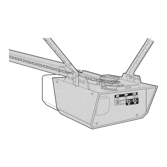
Page 28: Adjustthe Force
ADJUSTMENT STEP Adjustthe Force Without a properly installed safety reversal system, persons Force adjustment controls are located on the right panel of the (particularly small children) could be SERIOUSLYINJUREDor motor unit. Force adjustment settings regulate the amount of KILLEDby a closing garage door. power required to open and close the door. -
Page 29: Testthe Safetyreversalsystem
ADJUSTMENT STEP Testthe SafetyReversalSystem Without a properly installed safety reversal system, persons TEST (particularly small children) could be SERIOUSLYINJUREDor KILLEDby a closing garage door. • With the door fully open, place a 1-1/2" (3.8 cm) board (or a 2x4 laid flat) on the floor, centered under the garage door. •... -
Page 30: Operation
OPERATION IMPORTANTSAFETYINSTRUCTIONS To reducethe risk of SEVERE INJURYor DEATH: 1. READAND FOLLOWALL WARNINGSAND INSTRUCTIONS. 9. If one control (force or travel limits) is adjusted, the other control may also need adjustment. 2. ALWAYS keep remote controls out of reach of children. NEVER permit children to operate or play with garage door control 10. -
Page 31: Using The Wall-Mounted Door Control
Usingthe Wall-MountedDoor Control To Openthe DoorManually THE DOORCONTROL BUTTON Press the lighted push button to open or close the door. Press again to reverse the door during To prevent possible SERIOUSINJURYor DEATHfrom a falling the closing cycle or to stop the door while it's garage door: opening. - Page 32 CARE OF YOUR OPENER THE REMOTECONTROLBATTERY LIMIT AND FORCEADJUSTMENTS: Weather conditions may cause some FORCECONTROLS minor changes in door operation To prevent possible SERIOUSINJURYor DEATH: requiring some re-adjustments, • NEVERallow small children near batteries. particularly during the first year of •...
-
Page 33: Havinga Problem
HAVING A PROBLEM? 1. My doorwill not close and the light bulbs blink on my motor unit: The safety reversing sensor must be connected and Bell Wire aligned correctly before the garage door opener will move in the down direction. •... -
Page 34: Diagnostic Chart
Bell Wire Your garage door opener is programmed with self-diagnostic capabilities. The "Learn" button/diagnostic LED will flash a number of Safety Reversing times then pause signifying it has found a potential issue. Consult Sensors Diagnostic Chart below. Diagnostic Chart • Symptom:One or both of the Indicator fights on the safety reversingsensorsdo not glow steady. -
Page 35: Programming
PROGRAMMING NOTICE:If this Security,I_ garage door opener is operated with a non-rolling code transmitter, the technical measure in the receiver of the garage door opener, which provides security against code-theft devices, will be circumvented. Theowner of the copyright in the garage door opener does not authorize the purchaser or supplier of the non-rolling code transmitter to circumvent that technical measure. -
Page 36: To Add, Reprogram Or Change A Keylessentry Pin
To Add, Reprogram or Change a Keyless Entry PIN NOTE: Your new KeylessEntry must be programmed to operateyour garage door opener. USINGTHE "LEARN" BUTTON Tochangean existing, knownPIN If the existing PIN is known, it may be changed by one person without using a ladder. -
Page 37: Repair Parts
REPAIR PARTS 41A5665 Complete rail 144C56 Idler pulley 41A5595 Chain and cable 12D598-1 "U" bracket NOT SHOWN InstallationParts 183A163 Wear pads KEY PART DESCRIPTION 41A4166 Door control button 41A6140-2 Single-Function remote control housing (no circuit board) 10A20 3V2032 Lithium battery 29B137 Visor clip 41A2828... -
Page 38: Motor Unit Assembly Parts
Motor Unit Assembly Parts (Down) LIMIT SWITCH Brown Contact ASSEMBLY Wire \/"'_ _4"--.",L _ ....Wire Drive Gear _J_ffllf_/fffff_ Center L :imit (Up) Yellow contact contact wire PART KEY PART DESCRIPTION NO. NO. DESCRIPTION 41A5615 Chain Spreader 41D3058 Universal replacementmotor & bracket assembly 41C4220A Gear and sprocket assembly... -
Page 39: Accessories
WARRANTY RESTRICTION This Craftsman Garage Door Opener Limited Warranty does not cover light bulbs or repair parts necessary because of operator abuse or negligence, including the failure to install, adjust and operate this garage door opener according to instructions contained in the owner's manual. This limited warranty also does not cover any problems caused by interference. - Page 40 CONTENIDO Introducci6n Ajustes 27-29 Revisi6n de los simbolos y t_rminos de seguridad ....Ajuste el limite del recorrido ........Preparaci6n de la puerta de su cochera ......Ajuste lafuerza ..........Herramientas necesarias........Pruebe el sistema de retroceso de seguridad ..... Pruebe el Sistema de Protecci6n®...
-
Page 41: Preparaci6Nde La Puerta De Su Cochera
Preparaci6nde la puerta de su cochera Antes de comenzar: Para evitar una LESIONGRAVEo INCLUSOLA MUERTE: • Quite los seguros. • SIEMPRE Ilamea un t_cnico profesional para que le d_ servicio a su • Retire cualquier cuerda o cable que est_ conectado a la puerta. puerta de cochera si _sta se atora, se pandeao est,. -
Page 42: Planificaci6N
Planificaci6n Identifique laaltura y el tipo de su puerta de cochera. Reviseel _.reade su _,Hayotra puerta que d_ acceso a la cochera? Si no es asi, ser_. cochera y observe si alguna de las siguientes instalaciones corresponden necesario contar con el sistema de Ilave de emergencia Modelo 53702. a la suya. - Page 43 Planificaci6n(contin#a) INSTALACION CON PUERTASDE UNASOLAPIEZA Sin un sistema de retroceso de seguridad que funcione debidamente, • Generalmenteuna puerta de una sola pieza no requiere refuerzos al cerrar la puerta de la cochera se corre el riesgo de que las personas adicionales.
-
Page 44: Inventario De La Cajade Cart6N
Inventario de la Cajade Cart6n Su abridor viene empacado en una caja de cart6n que contiene el motor y piezas necesarias para el montaje e instalaci6n de su puerta se ilustran en las piezas que se muestran en la siguiente ilustraci6n. Tome nota de que la siguiente p_.gina.Conserve la caja y los materiales de empaque hasta los accesorios depender_.n del modelo que haya comprado. -
Page 45: Inventario De Piezas
Inventario de Piezas Antes de la instalaci6n, organice todas las piezas en grupos como se muestra en la siguiente ilustraci6n. TORNILLERIA Y PIEZAS PARA ELMONTAJE Tuercade Arandela 5/8 pulg. (2) Arandela de Tuercade 1/4-20 (2) 3/8 pulg. (1) 3/8 pulg.(1) Perno de 1/4-20xl-3/4 pulg. - Page 46 MONTAJE, PASO Monte e/fie/e insta/e e/tro/e Para evitar QUESE PELLIZQUE,conserve los manos y dedos lejos de No encienda ni use el abridorhasta que Ilegue al paso de la instalaci6n las juntas cuando monte el reil. correspondiente,de otra manera corre el riesgo de complicar el proceso de instalaci6n.
- Page 47 MONTAJE, PASO Fije el riel a la unidadde/motor Use SOLOel perno y la tuerca que vienen montados en la parte • Introduzca un tornillo de 1/4-20 x 2-1/2 de pulg., con arandela y superior del abridor para evitar que el abridor de la puerta de cochera separador, en el agujero del perno de protecci6n de latapa ubicado en se da_e SERIAMENTE.
-
Page 48: Montaje
MONTAJE, PASO Instale la cadenay cab/e Para evitar posibles LESIONESGRAVESen los dedos causadaspor las 1. Jale el cable alrededor de la polea Ioca y hacia el trole. partes m6viles del abridor de puerta de cochera: 2. Conecte la cable a la ranura de retenci6n del trole, como se muestra en •... -
Page 49: Apriete La Cadena
MONTAJE, PASO Apriete la Cadena • Gire la tuerca interna y ajuste la arandela; baje ambas por el eje Figura 1 roscado del trole, alej_.ndolasdel trole. Tuerca Eje roscado • Para apretar la cadena, gire la tuerca externa en la direcci6n que se Paraapretar externa Arandela del trole... -
Page 50: La M_Nsula Del Cabezal
INSTALACION, PASO Cielo raso Determine d6nde vaa insta/ar /a m_nsu/ade/cabeza/ sin acabado -- INSTALACION OPCIONALDE LA MENSULA DEL CABEZAL EN ELCIELO Pared RASO delantera Linen central Para evitar una posible LESIONGRAVEo INOLUSOLA MUERTE: vertical de la puerta de garaje • La m_nsula del cabezalDEBEquedar RJGIDAMENTE sujeta al soporte estructural en la pared delantera o en el cielo raso, de no Pedazo de madera ser asi es posible que la puerta de la cochera no retroceda cuando... -
Page 51: Instale La M_Nsula Del Cabezal
INSTALACION, PASO Montaje en la pared Instale la M_nsula de/Cabezal La m_nsula del cabezal se puedefijar a la pared justo por encima de la puerta de la cochera o en el cielo raso. Siga las instrucciones que sean m_.sadecuadas para su cochera. No instale la m_nsula del cabezal en un muro falso. -
Page 52: Coloque El Riel En La M_Nsula Del Cabezal
INSTALAClON, PASO Coloque el Riel en la M_nsula de/Cabezal • Coloque el abridor sobre el piso de la cochera debajo de la m_nsula del cabezal. Use el material de empaque como base para protegerlo. NOTA:Si el resorte de la puerta est# obstruyendo, va a necesitar ayuda. -
Page 53: Coloque El Abridor En Posici6N
INSTALACION, PASO Coloque el Abridor en Posici6n Para evitar que la puerta de cochera sufra da_os, apoye el riel del Siga las instrucciones correspondientes al tipo de puerta de su cochera, abridor de la misma sobre un pedazode madera de 5x10 cm como se muestra en la ilustraci6n. -
Page 54: Cuelgueel Abridor
INSTALACION, PASO Cuelgueel abridor Para evitar la posibilidad de una LESIONGRAVEsi se cae el abridor Aqui se muestran tres ejemplos distintos para la instalacidn; sin embargo, de la puerta de cochera, suj_telo FIRMEMENTE a los soportes es posible que su cochera no concuerde con ninguno de ellos. Las estructurales de la cochera. -
Page 55: Instale La Unidad De Control De La Puerta
INSTALACION, PASO Instale la unidadde control d e la puerta Para evitar la posibilidad de una LESIONGRAVEo INCLUSOLA Ubique el control de la puerta de manera que quede a lavista desde la MUERTEpor electrocuci6n: puerta y a una altura minima de 1.5 m (5 pies) donde los ni_os peque_os •... - Page 56 INSTALACION, PASO Instale /as luces Para evitar un posible SOBRECALENTAMIENTO del portabombillas: • NO utilice bombillas de cuello corto ni de tipo especial. • Instale bombillos de 75 vatios como m_.ximoen cada portal_.mpara. • NO utilice bombillas hal6genas. Utilice SOLObombillas Los bombillos deben ser de A19 cuello standard s61o.En cuanto se incandescentes.
-
Page 57: Requisitos Para La Instalaci6N El_Ctrica
INSTALACION, PASO 9 Requisitos p arala instalaci6n el ctrica Para evitar la posibilidad de una LESIONGRAVEo INCLUSOLA Para evitar dificultadescon la instalaci6n, no enciendani use el MUERTEpor electrocuci6n o incendio: abridor en este momento. • Cerci6rese de que el abridor no est_ conectado a la energia el_ctrica, Para reducir el riesgo de choque el6ctrico, su abridor para puerta de y desconecte la alimentaci6n el_ctrica al circuito ANTESde quitar la cochera viene con una clavija de conexi6n a tierra de tres patas. - Page 58 INSTALACION, PASO Instale e/Sistema de Protecci6n Cerci6rese de que la energia el_ctrica no est_ conectada al abridor Elsensor delsistemaderetroceso deseguridad debeestarinstalado y de la puerta de la cocheraANTES de instalar el sensor del sistema de alineado correctamente, antesdeque el abridor dela puertade retroceso de seguridad.
- Page 59 INSTALACION DE LAS MENSULAS Figura 1 INSTALACIONEN EL CARRILDE LA PUERTA(LADO DERECHO) Aseg_resede que el abridor no est_ conectadoa la corrienteel_ctrica. I I_l_ Oarri, Instale y alinee las m_nsulas de manera que los sensores est_n uno frente /Hiapuerta al otro en los lados opuestos de la puerta, a una distancia m_.ximade 15 cm (6 pulg.) del piso.
- Page 60 MONTAJEY CABLEADO DE LOS SENSORESDEL Figura5 SISTEMA DE SEGURIDADDE REVERSA Tuerca de mariposa 1/4-20 de pulg. • Deslice la cabezade un perno de coche de 1/4-20xl/2 de pulgada dentro de la ranura de los sensores. Usetuercas de mariposa para sujetar los sensores alas m_nsulas, con las lentes de cadasensor frente a frente a ambos lados de la puerta.
-
Page 61: Fije La M_Nsula De La Puerta
INSTALACION PASO Fije la mGnsula de la puerta En puertas de garaje de fibra de vidrio, aluminio o acero liviano ES Siga las instrucciones que correspondan al tipo de puerta que usted NEOESARIO colocar los refuerzos ANTESde instalar la m_nsula de la tenga, seg_n las ilustraciones siguientes o de la pr6xima p_.gina. - Page 62 PUERTAS DE UNA SOLA PIEZA: Lea y respetetodas las advertencias e instrucciones respecto a los refuerzos contenidas en la p_.ginaanterior, ya que son v_Jidastambi_n para puertas de una sola pieza. • Centre la m_nsula en la parte superior de la puerta, alineadacon la m_nsula del cabezal, tal se muestra en la ilustraci6n.
-
Page 63: Conecte E L Brazodela Puertaal Trole
INSTALACION, PASO 12 Polea Conecte e l brazodela puertaal trole Lo menos 20 cm A'- _8,.ig.) __: Siga las instrucciones que correspondan al tipo de puerta de cochera que usted tenga, como se muestra a continuacien yen la pD.gina siguiente. Figura 1 SOLOPARA PUERTASSECCIONALES / ro,e... - Page 64 TODAS LASPUERTASDE UNASOLAPIEZA Figura 5 RECTO 1. Arme el brazode/a puerta, Figura 5: IMPORTANTE:El ranura el7el brazo recto de la puerta DEBEvolt#ese del brazo curvado de la puerta. • Sujete las dos secciones de los brazos de la puerta (recto y curvo) a la mayor distancia posible, de manera que dos o tres de los orificios se sobrepongan uno al otro.
-
Page 65: Ajustes
AJUSTES, PASO Ajuste e//imite de/recorrido HACIA ARRIBA y HACIA ABAJO Si el sistema de retroceso de seguridad no se ha instalado debidamente, las personas (y los niSos pequeSosen particular) podrian AI ajustar el limite del recorrido de la puerta, se regula hasta qu6 punto sufrir LESIONESGRAVESo INCLUSOLA MUERTEcuando se cierra la _sta se detendr_,al abrir y al cerrar. -
Page 66: Ajuste Lafuerza
AJUSTES, PASO Ajuste la Fuerza Si el sistema de retroceso de seguridad no se ha instalado Los controles para el ajuste de la fuerza del abridor se encuentran en el debidamente, las personas (y los ni_os peque_os en particular) panel de posterior de la unidad del motor. Estos ajustes controlar_.n la podrian sufrir LESIONESGRAVESo INCLUSOLA MUERTEcuando se fuerza que ser_.necesaria para abrir y cerrar la puerta. -
Page 67: Pruebe El Sistema De Retroceso De Seguridad
AJUSTES, PASO 3 Pruebe e/sistema deretroceso deseguridad Si el sistema de retroceso de seguridad no se ha instalado PRUEBA debidamente, las personas (y los ni_os peque_os en particular) podrian • Abra completamente la puerta, coloque un pedazode madera de 3.8 cm sufrir LESIONESGRAVESo INCLUSOLA MUERTEcuando se cierra la (1-1/2 de pulg.) (o un pedazode madera de 5x10 cm (2x4 pulg.) puerta de la cochera. -
Page 68: Operaci6N
OPERACION INSTRUCCIONES IMPORTANTES DE SEGURIDAD Para reducirel riesgode LESIONES GRAVES o LAMUERTE: 1. LEA Y SIGA TODASLAS ADVERTENCIAS Y LAS INSTRUCCIONES 9. Cuando se ajusta uno de los controles (limites de fuerza o de DE OPERACION. recorrido), es posible que sea necesarioajustar tambi_n el otro control. -
Page 69: C6Mo Usar La Unidad De Control De Pared
C6mousar/a unidadde contro/de pared C6mo abrir /a puerta manua/mente BOTONDE CONTROLDE LA PUERTA Oprima el bot6n iluminado para abrir o cerrar la puerta. Optima de nuevo para que la puerta retroceda en el ciclo Para evitar la posibilidad de una LESIONGRAVEo INCLLISOLA de cierre o para detener la puerta cuando se est,. -
Page 70: Mantenimiento De Su Abridor De Puerta De Cochera
LA BATERIADEL CONTROLREMOTO MANTENIMIENTO DE SU ABRIDOR PUERTA DE COCHERA AJUSTESDE LIMITE Y FUERZA: Las condiciones climatol6gicas pueden CONTROLES DE FUERZA ocasionar cambios menores en la Para evitar la posibilidad de LESIONESGRAVES0 incluso LA MUERTE: operaci6n de la puerta, los cuales van a •... -
Page 71: Si Tiene Alg_N Problema
Si tiene alg_n prob/ema 1. La puerta no cierra y las luces de la unidad del motorparpadean: El sensor del sistema de retroceso de seguridad debe estar instalado y Cable de campana alineadocorrectamente para que el sistema de apertura de la puerta de la cochera se mueva en sentido descendente. - Page 72 Cable de campana El sbtema de apertura de la puerta cuenta con una funciSn de autodiagn6stico. El bot6n "Aprender"/LED de diagn6stico parpadear_ varias veces antes de detenerse, indicando que ha encontrado un posible problem& Consulte la tabla Sensor de seguridad de de diagn6stico a continuaci6n.
-
Page 73: C6Mo Agregar O Reprogramar Un Control Remoto Manual
COMO PROGRAMAR EL ABRIDOR A VISO:Si utiliza este abre puertas de garaje Security,F _ con un transmisor no dotado de un sistema de c6digos de salto (c6digo aleatorio), se ver_n circunvenidas las medidas t_cnicas incorporadas en el receptor del abridor para proteger contra los aparatos de captura de c6digos. El propietario de los derechos propiedad intelectual del abridor no autoriza ni al comprador ni al proveedor de un transmisor no dotado de un sistema de c6digos de salto (c6digo aleatorio) a circunvenir dichas medidas t_cnicas. -
Page 74: De La Unidad Del Motor
C6moagregar, reprogramaro cambiar un c6digode entradasin l/ave NOTA:Su nueva Entrada sin Ilave debe programarse para que opere el abridor de la puerta de su cochera. COMOUSAR EL BOTONLEARN(APRENDER) Para cambiar un PIN existente Si el PIN existente ya es conocido, una persona Io puedecambiar sin usar una escalera. -
Page 75: Accesorios
With loopfor attachingkeyring. GARANTiA GARANTIA L IMITADA DEABRIDOR DEPUERTA DECOCHERA CRAFTSMAN EL ABRIDOR DE PUERTA DE COCHERATIENE UNA GARANTiACOMPLETADE 90 DIAS Durante 90 dias a partir de la fecha de compra, las reparaciones de su abridor de puerta de cochera ser_n sin costo para usted si el abridor tiene defectos en materiales o mano de obra. - Page 76 Your Home For troubleshooting, product manuals and expert advice: www.managemylife.com For repair - in your home - of all major brand appliances, lawn and garden equipment, or heating and cooling systems, no matter who made it, no matter who sold it! For the replacement parts, accessories owner's manuals that you need to do-it-yourself.
Need help?
Do you have a question about the 139.53920DM and is the answer not in the manual?
Questions and answers