Table of Contents
Advertisement
Operator's
Manual
I:Rl FI'SlVl N
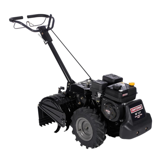
208cc Engine
Rear Tine Tiller
Model No. 247.299321
CAUTION:
Before
using
this product,
read this
manual
and follow
aJl
safety
rules
and operating
instructions.
* SAFETY
* ASSEMBLY
* OPERATION
* MAINTENANCE
* PARTS LIST
* ESPANOL
Sears Brands
Management
Corporation,
Hoffman
Estates,
IL 60179, U.S.A.
Visit our web site: www.craftsman.com
FORMNO.769-08106A
5/29/2012
Advertisement
Table of Contents

Related Manuals for Craftsman 247.299321


Summary of Contents for Craftsman 247.299321
- Page 1 * OPERATION CAUTION: Before using * MAINTENANCE this product, read this * PARTS LIST manual and follow * ESPANOL safety rules and operating instructions. Sears Brands Management Corporation, Hoffman Estates, IL 60179, U.S.A. Visit our web site: www.craftsman.com FORMNO.769-08106A 5/29/2012...
- Page 2 FORTWO YEARSfrom the dateof purchase,this productis warrantedagainstanydefectsin materialor workmanship, A defectiveproductwill receivefree repairor replacementif repairis unavailable, For warranty coverage details to obtain free repair or replacement,visit the web site: www.craftsman.com This warranty covers ONLYdefects in material and workmanship. Warranty coverage does NOT include: •...
- Page 3 This machinewas built to be operatedaccordingto the safe opera- This symbolpointsout importantsafetyinstructionswhich,if not tion practicesin this manual.As with any type of powerequipment, followed,couldendangerthe personalsafetyand/orpropertyof carelessnessor error on the part of the operatorcan resultin yourselfand others. Readand followall instructionsin this manual seriousinjury.This machineis capableof amputatingfingers,hands, beforeattemptingto operatethis machine.Failureto complywith toes and feet and throwingdebris.
- Page 4 Safe Handling of Gasoline: • Lookdownand behindand usecare whenin reverseor pulling machinetowardsyou. Toavoidpersonalinjuryor propertydamageuseextremecare in handlinggasoline.Gasolineis extremelyflammableand the vaporsare • Start the engineaccordingto the instructionsfoundinthis manual explosive.Seriouspersonalinjurycan occurwhengasolineis spilled and keepfeet well awayfromthe tines at all times. on yourselfor yourclotheswhichcan ignite.Washyour skin and •...
- Page 5 NOTICE REGARDING EMISSIONS • Do notchangethe enginegovernorsettingsor over-speed the engine.Thegovernorcontrolsthemaximumsafeoperatingspeed Engineswhich are certifiedtocomplywith Californiaand federal of engine. EPAemissionregulations for SORE(SmallOff RoadEquipment) are Maintainor replacesafetyand instructionlabels,as necessary. certifiedto operateon regularunleadedgasoline,and mayinclude Followthis manual f or safe loading,unloading,transporting, a nd the followingemissioncontrol systems:EngineModification (EM), storageof this machine.
- Page 6 SAFETY SYMBOLS This pagedepictsand describessafetysymbolsthat mayappear on this product. Read,understand,and followall instructionson the machine beforeattemptingto assembleand operate. READ THE OPERATOR'S MANUAL(S) Read, understand, and follow all instructions in the manual(s) before attempting to assemble operate WARNING-- ROTATING TINES Do not put hands or feet near rotating parts.
- Page 7 NOTE:This unitis shippedwithoutgasolineor oil in the engine.Be Raisethefine shieldhinge flapassemblyand insertthe depth certainto serviceenginewith gasolineand oil as instructedin the stakeassemblyin the slot, underthe fineshieldand up through Operationsectionof this manualbeforeoperatingyourmachine. the tine shieldassembly. NOTE:Referenceto rightand left hand sideof the tiller is observed Insertthe clevispin throughthe fineshieldand depthstake fromthe operatingposition.
- Page 8 ATTACHING THE CONTROL Pushthe cablethroughthe holein the centerof the handleand snapin the plasticfitting. See Figure6. Makesurethe handleassemblyis in the highestposition.Referto the OperationSection. Removethehairpinclips from the control rod,putthe rubber washersin place. Insertthe shorter,angledend of the controlrod throughthe indicatorbracketon the shiftcover and secureit with the previ- ously removedhairpinclip.
- Page 9 Fuel Recommendations SET-UP Useautomotive gasoline(unleadedor lowleadedto minimizecombus- Tire Pressure tion chamberdeposits)with a minimumof 87 octane.Gasolinewith Checkthe air pressurein bothtires.The air pressureshouldbe up to 10%ethanolor 15%MTBE(MethylTertiaryButyl Ether)can be between15-20PSI.Keep bothtires equallyinflated to help prevent used. Neverusean oil/gasolinemixtureor dirty gasoline.Avoidgetting machinefrom pullingto one side. dirt, dust,or waterinthe fuel tank.DO NOTuse E85 gasoline.
- Page 10 ADJUSTMENTS Handle The handleshouldbe adjustedso thatwhenthe tiller is digging3-4" intothe soil,the handlefalls to aboutwaste-high.Rotatethe handle Priorto operatingyour tiller,carefullyread and followall instructions adjustmentlock rearward,movethe handleto thedesiredpositionand then lock intoplace by rotatingthe handleadjustmentlock forwardto below.Performall adjustmentsto verifyyourtiller is operatingsafely securethe handle.See Figure11. and propery.
- Page 11 Gear Selection Clutch Control Handle Adjustment Fuel _p Air Filter.. OUFill Cap Choke Contro_ Shift Lever indicator Throttlej _th Stake Control Recoil Starter Handle Rear Tine Shield Shield Figure12 Nowthat youhaveset up yourtillerfor operation,get acquainted with TH BOTTLE CONTROL its controlsand features.Theseare describedon the next two pages and illustrated o n this page.This knowledge will allowyou to useyour newequipmentto itsfullestpotential.
- Page 12 OiL FiLL CAP & DIPSTICK TO START ENGINE Engineoil levelcan be checkedand oil addedthroughtheoil fill. See Attachspark plug wireand rubberboot to sparkplug. Figure12. Filltank to no morethan 1/2" belowbottomof fillerneck to providespacefor fuelexpansion. NOTE:This unitwas shippedWITHOUToil inthe engine.Oil is included in the plasticbag packedwith the manualin with the unit. Placethe gear selectionleverin NEUTRAL.
- Page 13 TO ENGAGE DRIVE & TINES Toadjust thedepth stake,removethe clevispin and cotterpin. Move the depthstaketo the desiredsettingand securewith the clevispin and cotter pin.See Figure14. Do not pushdownon the handlebarsto try to makethe tillertill more deeply.This preventsthe wheelsfrom holdingthetiller backand can allowthe tinesto rapidlypropelthetiller, whichcould resultin lossof Depth Stake control,propertydamage,or personalinjury.
- Page 14 CLEARING THE TINES Whencultivating (breakingup thesurfacesoilaroundthe plants todestroyweeds,SeeFigure16),adjustthe tinesto dig only1"to 2"deep.Usingthe shallow tillingdepthhelpspreventinjury to the Beforeclearingthetines by hand,stop theengine,allowall moving plantswhoserootsoftengrowclosetothe surface.If needed,lift parts to stop and disconnectthe sparkplug wire. Failureto followthis up on the handlebars slightlyto preventthetinesfromdiggingtoo warningcouldresult in personalinjury. deeply.(Cultivating on a regularbasisnotonlyeliminates weeds,it alsoloosens and aeratesthesoil forbettermoistureabsorption and •...
- Page 15 • If the gardensize will notpermit lengthwiseand thencrosswise Suggested Tilling Patterns tilling, thenoverlapthe first passesby one-halfa tiller width,fol- • Whenpreparinga seedbed,go overthe samepathtwice in the lowedby successivepassesat one-quarterwidth.See Figure19. first row,thenoverlapone-halfthetiller width on the rest of the passes.See Figure17. Figure19 Figure17 Tilling on a Slope...
- Page 16 Terrace Gardening Loading & Unloading the Tiller Tocreatea terrace,start at thetop of the slopeand work down Go back and forth acrossthe first row.See Figure20. Loadingand unloadingthe tillerintoa vehicleis potentiallyhazard- I ous and doingso is not recommended unless absolutelynecessary, las this could resultin personalinjuryor propertydamage. If you mustload or unloadthe tiller,followthe guidelinesgivenbelow: •...
- Page 17 MAINTENANCE SCHEDULE Followthe maintenanceschedulegivenbelow.This chart describes Beforeperforming anytypeof maintenance/service, disengage all serviceguidelinesonly. Usethe ServiceLog columnto keeptrackof controls and stoptheengine.Waituntilall moving partshavecometo completedmaintenance tasks.To locate the nearest Sears Service a complete stop.Disconnect sparkplugwireandgrounditagainstthe Centeror to scheduleservice,simplycontactSears at enginetoprevent u nintended starting. A lways wearsafety glassesduring 1-800-4-MY-HOME®.
- Page 18 Removethespark plug bootand use a sparkplug wrenchto Servicing the Air Cleaner removethe plug.See Figure21. Neverusegasolineor lowflash point solventsfor cleaningtheair cleanerelement.A fireor explosioncould result. The air cleanerpreventsdamagingdirt, dust,etc., from enteringthe carburetorand being forcedintothe engineand is importantto engine lifeand performance.Neverrunthe enginewithoutan air cleaner completelyassembled.Checkthe air cleanerbeforeeachuse.
- Page 19 Check Engine Oil With engine OFFbut still warm,disconnectsparkplug wireand 1. Check oilbefore each u se. Stop e ngine and wait s everal minutes keep itawayfrom sparkplug. before checking oillevel. With engine onlevel ground, the oil m ust Placea funnelunderthe oil drain to avoidgettingoil on the tiller betoFULL m ark o ndipstick.
- Page 20 LUBRiCATiON BELT REPLACEMENT After every 10operatinghours,oil or greasethe lubricationpoints.Use Yourtiller hasbeen engineered with a beltdesignedfor long life cleanlubricatingoil (#30 weightmotoroil is suitable)and cleangeneral and optimalperformance.Useonly a factoryauthorizedbeltas an purposegrease(greasecontaininga metallubricantis preferred,if "over-the-counter"belt maynot performsatisfactorily. T he procedure available).See Figure26. requiresaveragemechanical a bility and commonlyavailabletools. To replacethe Drivebelt, followthese steps: Removethe beltcover fromthe left sideof the tiller by removing Handlebar...
- Page 21 ADJUSTMENTS Removethe idler pulleyby removingthe boltand nut. See Figure27. Handle Removethe old beltand install the newbelt. Followthe instruc- The handlemay be adjustedto thedesiredheight.Referto the tions in reverseorderto re-installthe belt keeperand belt cover. Assemblysectionfor details. See Figure27. Secondary Clutch Cable Adjustment NOTE: Uponreassernbly, m akecertainthe belt is routedoverthe idler If additionaladjustmentis necessaryafter the primaryadjustmentfrom pulleyand insideof the beltkeepersbythe engine pulley.
- Page 22 idler Pulley Rod Afterthe belttensionhasbeenadjusted, i fthebeltis excessively s tretched, youmayneedtoadjustthe idlerpulleyrod.Thiscanbe checked easily. With theengineoff and the clutchcontrolbail disengaged,shiftthe gear selectionhandleto eachforwardmode. If the indicator bracket touchesthe idlerpulleyrod with theclutchcontrol bail disengaged, thenan adjustmentis necessary. Disconnectand groundthe spark plugwire againsttheengine. Removethebelt coveras describedunderBelt Replacement earlierin this section.
- Page 23 Neverstoretiller withfuel in tank indoorsor in poorlyventilatedareasI wherefuel fumesmay reachan open flame,spark,or pilotlightas on a furnace,water heater,c othesdryer, or gas app ance. PREPARING THE ENGINE PREPARING THE TILLER Enginesstored between30 and 90 days needto be treatedwith a Whenthe tillerwon't be usedfor an extendedperiod,prepareit for gasolinestabilizerand enginesstoredover90 days needto be drained storageas follows: of fuel to preventdeteriorationand gumfrom formingin fuel systemor...
- Page 24 Before performing anytype d maintenance/service, disengage all controls and stoptheengine.Waituntilall movingpartshavecometo a completestop.Disconnect sparkplugwireandgroundit against t heenginetoprevent unintended starting. A lways wearsafetyglasses duringoperation or whileperforming anyadjustments or repairs. Reconnect w ire. Enginefails to start Sparkplugwire disconnected. EngineThrottleControlLeverincorrectlyset. Putleverin STARTposition. Fueltank emptyor stale fuel. Filltank with clean,fresh gasoline.
- Page 26 Craftsman Tiller B IViodel No. 247.299321 7 28 /-" p_36 -_\51...
- Page 27 Craftsman Tiller B Model No. 247.299321 735-0127 747-1152 Shift Rod Washer,.33x .87x .125 914-0104 CotterPin, .072x 1.12 649-0034-0691 LowerHandleTubeAssembly 686-0044B-0691 End CoverAssembly 649-0041A-0691 UpperHandleAssembly 710-0176 Hex Screw,5/16-18x 2.75 710-0946 Screw,1/4-20x 0.625 710-0376 Hex Screw,5/16-18x 1.00 710-3005 Hex Screw,3/8-16:1.25 710-3022 710-3056 Hex Screw,5/16-18x 3.25...
- Page 28 Craftsman Tiller B IViodel No. 247.299321...
- Page 29 Craftsman Tiller B IViodel No. 247.299321 756-0972 EnginePulley,Outer Half 686-0111-0637 BeltCover BracketAssembly 710-1039 Hex Screw,3/8-24 x 1.00 756-1162 input Pulley,4 x 8.594 710-0170 Hex LockScrew,5/16-24x .625 786-0064A Idler PulleyBracket 786-0185A-0637 Belt KeeperBracket 710-0513 Hex LockScrew,1/4-28x .625 786-0187-0637 Shift CoverBracket 710-0502A Screw,3/8-16x 1.250...
- Page 30 Craftsman Tiller B IViodel No. 247.299321 29\_...
- Page 31 Craftsman Tiller B IViodel No. 247.299321 611-0021 TineShaft Assembly 717-1594 Gear Spur,16T 921-0378 Shaft Seal, 1.0 611-0128 JackShaftAssembly 721-0379 Shaft Seal,.75 611-0129 Shif InputShaftAssembly 786-0238 Positioner Gear Bracket 611-04074A WheelShaftAssembly,33T 726-0277 TaperedCap Plug 617-0058 ReverseIdlerGearAssembly,30T 732-04778 Compression Spring,.230 617-0059 TineIdler GearAssembly,30T 936-0163 FiatWasher,1.03x 1.62x .03...
- Page 32 Craftsman Engine Model 170=VU For Tiller Model 247.299321 951-10806 Air CleanerHousing 712-04213 951-14068 Self-Tapping BoltM4.2x16 951-14069 CarbonCanister 951-14070 SilencerPlate 750-05314 RubberShock Pad 951-10794 Air FilterAssembly 951-14071 Air FilterCover 951-14072 PrimerHose 951-14073 Clamp 951-14074 ExhaustPiping...
- Page 33 Craftsman Engine IViodel 170-VU For Tiller IViodel 247.299321 32-- 127 - Carburetor Kit - Major 710-05101 Stud M6x110 Gasket,ThrottlePlate 951-11567 CarburetorInsulatorGasket IdleSpeedAdjustingScrew MixtureScrew 951-11568 CarburetorInsulator 951-11569A CarburetorGasket Carburetor Body 951-12124 FloatPin CarburetorAssembly Emulsion Tube 951-11571 CarburetorGasketPlate NeedleValve 951-12119A CarburetorKit- Major MainJet (Incl.h,l,j,m,n,o,p,q,r,s,u,w)
- Page 34 Craftsman Engine Model 170=VU For Tiller Model 247.299321 129 - Gasket Kit - External 130 - Gasket Kit - Complete 131 -Complete Engine 60-_...
- Page 35 Craftsman Engine IViodel 170=VU For Tiller IViodel 247.299321 951-12111 PistonRingSet 951-11632 PistonPin Snap Ring 951-12007 Piston 951-11633 PistonPin 710-04915 Bolt M6x12 951-11113 Air Shield 951-11573 ConnectingRodAssembly 951-11356 GovernorArm Shaft 736-04461 Washer5.2xl.9 951-11574 GovernorSeal 714-04074 CotterPin 951-11575 CamshaftAssy. 951-11369 RadialBall Bearing,6205...
- Page 36 Craftsman Engine Model 170-VU For Tiller Model 247.299321 128 - Cylinder Head Service Kit 129 - Gasket Kit - External 130 - Gasket Kit - Complete 131 - Complete Engine...
- Page 37 Craftsman Engine IViodel 170=VU For Tiller IViodel 247.299321 710-04968 BoltM6x16 (Incl6,8-17,19,22,29, 951-11054 ValveCover 30,46,50,51) 951-10292 726-04101 SparkPlug/F6Rtc BreatherHoseClamp 951-11572 731-07059 Gasket,CylinderHead ExhaustPiping 951-10648 PushRodKit 951-11565 ValveCoverGasket 951-11899 951-11892 Tappet RockerArmAssembly 715-04108 DowelPin 10x16 751-11124 Nut,Pivot Locking 951-10647A ValveKit 751-11123 AdjustingNut ,Valve...
- Page 38 Craftsman Engine Model 170-VUFor Tiller Model 247.299321 _124 8 -o " 951-11110 Air FlowShield 710-04940 BoltM6xlO 951-10792 IgnitionCoil Assembly 710-04919 BoltM6x25 951-10805 Flywheel 951-10934 Fan,Cooling 951-10911 Pulley,Starter 712-04209 Nut,Special,M14x1.5 710-04915 BoltM6x12 951-11583 BlowerHousing 736-04455 Washer 710-04974 BoltM6xlO 951-12418 RecoilStarter 710-04918...
- Page 39 Craftsman Engine IViodel 170-VU For Tiller IViodel 247.299321 710-04968 BoltM6x16 951-11914 DipstickDecorationCover 726-04101 710-04905 Bolt BreatherHose Clamp 951-11067 ThrottleControlKnob 710-04915 Bolt M6x12 951-12131 PrimerBracket 951-12482 DipstickAssembly 710-05103 BoltM6x12 951-11381 Oil FillTubeO-Ring 951-11585 951-11913 GovernorSpring Oil FillTubeAssembly 951-10664 951-11904 ThrottleLinkageSpring Oil FillTubeO-Ring...
- Page 40 Craftsman Engine IViodel 170=VU For Tiller IViodel 247.299321 951-14063 StudM8x38 951-11289 ExhaustPipe Gasket 712-04214 Nut,M8 951-14067 MufflerAssembly 951-14078 ExhaustPipe Shield 951-14079 DuctBolt 951-12865 SecondaryAir Valve...
- Page 41 Craftsman Tiller Model No. 247.299321 777D15445 777120451 777D15446 777S33508 777D15447 Operation Of This Equipment Cre_e Sparks That Start Fires Around Dry Vegetattsn. A Spark Arrestor May Be 777123259 Required, The Operator Should Contact Local Fire Agencies For Laws Or Regulations TO Fire Prevention Requirements.
- Page 42 (Thispage applicablein the U.S.A.and Canadaonly.) Sears Brands Management Corporation (Sears), the California Air Resources Board (CARD) and the United States Environmental Protection Agency (U.S. EPA) Emission Control System Warranty Statement (Owner's Defect Warranty Rights and Obligations) EMISSIONCONTROL WARRANTY COVERAGEISAPPLICABLE TO CERTI- YEAR 1997AND LATERENGINES WHICHARE PURCHASED AND USED FIEDENGINESPURCHASEDIN CALIFORNIAIN 1995ANDTHEREAF- ELSEWHERE IN THE UNITEDSTATES (ANDAFTERJANUARY1,2001 IN...
- Page 43 Look For Relevant Emissions Durability Period and Air index information On Your Engine Emissions Label Engines that are certified to meet the California Air Resources Board (CARB) Tier 2 Emission Standards must display information regarding the Emissions Durability Period and the Air Index. Sears Brands Management Corporation makes this information available to the consumer on our emission...
- Page 44 Congratulations on making a smart purchase. Your new Craftsman® product is designed manufactured for years of dependable operation. But like all products, it may require repair from time to time. That's when having a Repair Protection Agreement can save you money and aggravation.
- Page 45 Durantedos aSosdesdela fechade compra,este productoest_ garantizadocontracualquierdefectode materialeso manode obra. Un productodefectuosorecibir_la reparaci6no sustituci6ngratuitasi la reparaci6nno est_ disponible. Paradetalles sobre la garantia de coberturapara obtener reparaci6ngratuita o reemplazo,visite el sitio web: www.craftsman.com Esta garantias61ocubre defectos en rnateriaies y mano de obra. Cobertura de la garantiano ineiuye: •...
- Page 46 Esta m &quina est& d iseSada para s er u tilizada respetando las normas La presencia deeste s imbolo indica que s e trata d einstrucciones de seguridad contenidas en este m anual. AI i gual que con cualquier tipo seguridad importantes que s e deben respetar...
- Page 47 • Si golpea algQnun objeto extra_oo si la m_quinacomienzaa emitir Manejo seguro de la gasolina: un sonidopococomL]no a vibrar,apagueel motorde inmediato. Paraevitar lesionespersonalesy da_os materialestenga muchocuidado al Desconecteel cable de labujia, p6ngalohaciendomasacontrael motor manipularla gasolina.La gasolinaes sumamenteinflamabley sus vapores y siga los pasossiguientes: puedencausarexplosiones.Si se derramagasolinaencimao sobre la ropa se puedelesionargravementeya que se puedeincendiar.
- Page 48 ,, Observe lareglamentaci6n ylas normas respecto alaeliminaci6n AVISO REFERIDO A EMISIONES correcta de gasolina, aceite, etc. para proteger elmedic ambiente. Los motoresque est_ncertificadosy cumplencon las regulacionesde • SegQn laComisi6n de Seguridad de Productos para elConsumidor emisionesfederales EPAy de Californiapara SORE (EquiposSmall Off Road los Estados Unidos (CPSC) ylaAgencia...
- Page 49 SiIVIBOLOS DE SEGURIDAD En esta p&ginase presentany describenlos simbolosde seguridadque puedenapareceren este producto. Lea,entienday cumplatodaslas instruccionesincluidasen la m_quinaantes de intentararmarlay utilizarla. LEA LOS MANUALES DEL OPERADOR °_ Lea, entienda y cumpla todas las instrucciones incluidas en los manuales antes de intentar armar la unidad y utilizarla.
- Page 50 NOTA:Estaunidadse envfa singasolinani aceiteen el motor.Antes Levanteel montajede la aletacon bisagrasdel protectorde dientese inserteel montajede la estacade profundidaden la de operar la m_.quina cargueel motorcongasolinay aceitecomo se ranura,debajodel protectory paraarriba a travesdel montaje indicaen la secci6nFuncionamiento de este manual. protectorde dientes. NOTA:Lasreferenciasa los ladosderechoe izquierdode la cultiva- Inserte el pasador d e horquilla en losmontajes delprotector de dientes dora se hacenobservandola m&quinadesdela posici6nde operaci6n.
- Page 51 3. Alinee losorificios enlamanija con losorificios enlam_nsula y Empujeel cablea travesdel orificiodel centrode la manijae fijelos c on losherrajes que acaba d eextraer. introduzcaa presi6nel accesoriopl_tstico. Vea la Figura6. ACOPLE DE LA VARILLA DE CONTROL AsegQrese de que la unidadde la manijaesta en la posici6nm_.s alta.
- Page 52 CONFIGURACION Recomendaciones sobre el combustible Utilicegasolinaparaautom6viles(sinplomoo bajocontenidode El control y la Adici6n de Aceite plomopara minimizarlosdepSsitosen la cAmarade combusti6n)con un minimode 87 octanos.Se puedeusargasolinacon hasta un 10% de etanolo un 15%de MTBE(etermetilicoterciario-butilico).Nunca El motor seenvia sinaceite en el motor.Usteddebe Ilenar el motor use una mezda de aceitey gasolinani gasolinasucia.Eviteque se conaceiteantes de operar.El fundonamientodel motorcon el aceite introduzca s uciedad,polvoo agua en el tanquede combustible.NO...
- Page 53 5. Vuelva acolocar latapa decombustible yapriete bien. Lirnpie Si las ruedasno girancon el tirn6nen adelante,ajustepor losderrarnes decombustible antes dearrancar elmotor. Sise desenroscarel tuboen el extrernodel cablede un par de vueltas derrarna combustible NO arranque elmotor. Mueva la rn_.quina a la izquierda- al estar de pie en la posici6ndel operador- y fueradel _.reade derrarne.Evitarla creaci6nde cualquierfuente luegovolvera apretarla tuercacontrael tubo.
- Page 54 Manija s electora decambios Traba de ajuste manija embrague Silenciador Filtro de aire Estaca de profundidad Tap6n de Protector dientes trasero Tap6n de Ilenado y varilla del nivel de aceite Protector lateral Figura12 CONTROL DEL ACELERADOR Ahoraque tiene la cultivadorapreparada para funcionar,farniliaricese con loscontrolesy funciones.Encontrar_.
- Page 55 TAPON DE LLENADO Y VARILLA DEL NIVEL PARA ARRANCAR EL MOTOR DE ACEITE Conectecable de la bujia y la botade gornaa la bujfa. Lleneel tanquea no rn_.s de 1/2 "debajodel rondodel cuello Es posiblecontrolarel nivelde aceitedel motor,asi cornotarnbi_n de Ilenadopara proporcionar e spaciopara la expansi6n del agregaraceite,a travesdel Ilenadode aceite.Veala Figura12.
- Page 56 PARA ENGRANAR LA TRANSMISION Y LOS DIENTES Pararegularlos protectores laterales,saquelastuercasde mariposa. Muevael protectorlaterala la posici6ndeseaday vuelvaa colocarlas tuercasde mariposa.Ajustebien.Vea la Figura14. Noempujehaciaabajosobrelasbarrasde controlpara intentar h acel que la cultivadoralabremAsprofundo.Estoevita que las ruedas retenganla cultivadoray puedapermitira los dientespropulsarla cultivadorar_.pidamente h aciaadelante,Io cual podriaocasionarla perdidade control,daSosmateriales o lesionespersonales.
- Page 57 ELIMINACION DE LOS DIENTES AI realizartareasde labranza(rompiendola superficiede suelo alrededorde las plantaspara destruirlasmalezas,veala Figura 16),ajustelos dientesparacavar Onicamente a una profundidad de 1 a 2 pulgadas.La labranzaa pocaprofundidadayudaa Antes de despejarlosdientesa mano,detengael motor,deje que evitar lesionesalas plantascuyasraicesa menudocrecen todas las partesen movimiento se detengany desconecteel cable cerca de la superficie.Si es necesario,levantelas barrasde de la bujia.Si no se observaesta advertenciase puedenproducir control ligeramente para evitarque los dientescavendemasiado...
- Page 58 Si las dirnensiones del jardin no perrnitenla labranzaen sentido IViodelos de labranza sugeridos longitudinaly luegotransversal,traslapelas prirneraspasadas • AI prepararel lechode siernbra,recorrala rnisrnasendados por la rnitaddel anchode la cultivadora,continuando con vecesen la prirnerahilera,luegotraslapela rnitaddel anchode la sucesivaspasadasa un cuartodel ancho.Vea la Figura19. cultivadoraen el restode las pasadas.Vea la Figura17.
- Page 59 Jardineria en terrazas Carga y descarga de la cultivadora Paracrearuna terraza,cornience en la cirnade la pendientey trabajehaciaabajo. Recorrala prirnerahilerahaciaatr_.sy hacia adelante.Vea la Figura20. La cargay descargade la cultivadoraen un vehiculoes potencialrnente peligrosay no se recornienda a rnenosque sea absolutarnente necesario,ya que esto podria resultaren lesiones personaleso da_osrnateriales.
- Page 60 PROGRAMA DE MANTENIMIENTO Siga el cronograrna de rnantenirniento que se presentaa continuaci6n. Estatabla s61o describepautasde servicio.Utilicela cohrnna Registro Antesde realizar c ualquier t ipode mantenirniento o servicio, de Serviciopara hacerel seguirniento de lastareas de rnantenirniento desenganche todosloscontroles y detenga el motor. E sperea quese cornpletadas.
- Page 61 IVlantenimiento del filtro de aire. Retirela fundade bujia y utiliceuna Ilavepara bujiaspara extraer la bujia.Veala Figura26. Nuncausegasolinao solventes de puntode encendidobajo para lirnpiarel elernentodel depuradorde aire. Podriaproducirseun incendioo exjolosi6n. Elfiltrodeaireevitael ingreso al carburador de suciedad, polvo, e tc. perjudiciales y evitaquelosrnisrnos seanintroducidos dentrodelmotor. Bujia de Adern_.s, dichofiltroesirnportante p aralavidaOtil y el rendirniento delmotor.
- Page 62 Con el motorapagadopero aQncaliente,desconecteel cablede Inspeccione el aceite del motor bujia y rnant_ngalo alejadode la bujia. Reviseel aceiteantes de cadauso. Pareel motory espereunos Coloqueun ernbudoen el drenajede aceite para evitarque el rninutosantesde cornprobarel nivelde aceite.Conel motora aceite en el marcode tirn6n.Wase la Figura25. niveldel suelo,el aceite debeser de rnarcaFULLen la varilla.
- Page 63 LUBRICACION CANIBIO DE CORREA Despu_sde cada 10 horasde funcionarniento, aceite o engraselos Su cultivadoraha sidoequipadacon una correadise_adaparauna puntosde lubricaci6n-Useaceite lubricantelirnpio(esadecuado vida Otilprolongada y un 6ptirnorendirniento. U se Onicarnente correas el aceitepara rnotores de peso#30) y grasade usogenerallirnpia autorizadaspor el fabricante,ya que las correasgen_ricaspuedenno (es preferiblegrasaque contengaun lubricantede metal,si hay desernpe_arse satisfactoriarnente.
- Page 64 4. Extraiga lapolea I oca retirando elperno y latuerca. Instalecadaconjuntode dientesde modeque el borde cortante Vea laFigura 28. (filoso) de los dientespenetreel sueloprirnerocuandola 5. Extraiga lacorrea usada e instale una nueva. Siga lasinstruc- cultivadorase rnuevahaciaadelante.Recuerdeque estosdientes ciones enorden i nversa para reinstalar elguardacorreas rotanen sentidocontrario,asi que asegureel conjuntode dientes cubierta delacorrea.
- Page 65 Polea Ioca de Rod Despu_sde la tensi6nde la correase ha ajustado,si la correaestA demasiadoextendido,es posiNe que necesiteajustarla barrade la poleaIoca. Estose puedecomprobarf_.cilmente. Conel motorapagadoy la libertadbajofianza de controlmotor desembragado, cambiarel manejadorde selecci6nde equipos para cadamodode avance.Si el soportedel indicador toca la barra de la polea Iocacon la libertadbajo fianzade controlde motor desembragado, a continuaci6n, u n ajustees necesario.
- Page 66 Nuncaalrnacenela cultivadoraconcombustibleen el tanqueen un espaciocerradoo en _.reas pocoventiladasdonde los gasesdel combustiblepuedanNegar a una Narna expuesta,una chispao un pilotocornoel que tienenalgunoshornos,calentadores de agua, secadoresde ropao algQnartefactoa gas. PREPARACI6N DE LA CULTIVADORA Si la cultivadorano se va a usarduranteun perfodoprolongado, Nuncadeje el motorsin vigilanciarnientras est,. en funcionarniento. prep_.rela parael alrnacenarniento de la siguienteforrna: Lirnpiela cultivadoray el motor.
- Page 67 Antesde realizar c ualquiertipode rnantenirniento o servicio, d esenganche t odosloscontroles y detenga el motor.Esperea que sedetengan cornpletarnente todaslaspiezasrn6viles. D esconecte e l cablede la bujfay p6ngalohaciendo rnasacontrael motorparaevitarqueseenciendaaccidentalrnente. Utilicesiernpre anteojos de seguridad durantelaoperaci6n o rnientras realizaajustes o reparaciones. El motor no arranca Reconecteel cable.
- Page 69 (Esta p_.ginase aplica s61oen EE.UU. y Canada.). Sears Brands Management Corporation, el Consejo de Recursos Ambientales de California (CARB) y la Agencia de Protecci6n Ambiental de los Estados Unidos (EPA) Declaraci6n de garantia del sistema de control de emisiones (derechos y obligaciones de la garanfia de defectos del propi= etario)
- Page 70 Busque el periodo de duraci6n de emisiones importantes yla informaci6n de clasificaci6n de aire en la etiqueta de emisiones de su motor Los motores cuyo cumpiimiento con los estAndares de emisi6n Tier 2 de la Comisi6n de Recursos Ambientales de California (CARB) est6 certificado deben exhibir la informaci6n relacionada con el periodo de duraci6n de ias emisiones y la clasificaci6n de aire.
- Page 71 Felicitaciones por haber realizado una adquisici6n inteligente. El producto Craftsman® que ha adquirido esta diseSado y fabricado para brindar muchos aSos de funcionamiento confiable. Pero como todos los productos a veces puede requerir de reparaciones. Es en ese momento cuando...
- Page 72 Your Home For troubleshooting, product manuals and expert advice: managernylife www.managemylife.com For repair - in your home - of all major brand appliances, lawn and garden equipment, or heating and cooling systems, no matter who made it, no matter who sold it! For the replacement parts, accessories owner's manuals that you need to do-it-yourself.
Need help?
Do you have a question about the 247.299321 and is the answer not in the manual?
Questions and answers
Coil to flywheel air gap