Table of Contents
Advertisement
Owner's
Manual
Model No.
139.53963SRT
For Residential Use
Only
Caution:
Read and follow all
safety rules and
operating Instructions
before first use of this
product.
Fasten the manual
near the garage door
after installation.
Complies with UL 325 f|l
_
regulations effective
January 1, 1993
I:RRFTSMRN®
GARAGE DOOR OPENER
1/2 HP
• Safety Precautions
• Assembly
• Installation
m Adjustment
• Care and Maintenance
• Operation
• Troubleshooting
• Parts List
-.-w.i
,,
Sears,
Roebuck
and Co., Hoffman
Estates,
IL 60179
U.S.A.
Advertisement
Table of Contents

Related Manuals for Craftsman 139.53963SRT


Summary of Contents for Craftsman 139.53963SRT
- Page 1 Owner's Manual Model No. 139.53963SRT For Residential Use Only I:RRFTSMRN® GARAGE DOOR OPENER 1/2 HP Caution: • Safety Precautions Read and follow all • Assembly safety rules and • Installation operating Instructions m Adjustment before first use of this • Care and Maintenance product.
-
Page 2: Table Of Contents
Contents Complete the safety reversing sensor installation..22 Safety alert symbol review ..........2 Install the lights and lens .......... 23 Safety information, precautions, tools ......3 Attach the emergency release rope and handle ..23 Testing your garage door for binding & balance ..3 Fasten the door bracket(sectional door) .... -
Page 3: Safety Information, Precautions, Tools
Safety Information and Precautions; Tools To avoiddamage to thegaragedoorend opener, d isable An unbalanced g aragedoormightnotreverse w hen locksbeforeInstallingand operating the opener.Use a required andsomeone under the doorcould be seriously injuredor killed. woodscrewor nailto holdlocksinthe "open'(unlocked) position. If yourgaragedoorbinds,sucksor Is out ofbalance, c all for professional garagedoorservice.Garage doors,door Operation at otherthan 120V 60 Hz will cause opener springs, c ables,pulleys, b rackets, a nd theirhardware are... -
Page 4: Carton Inventory
Carton Inventory Your garage door opener is packaged in one carton which contains the power unit and all parts illustratedbelow, If anything is missing, carefully check the packing material. Parts may be "stuck"in the foam. KEEP THE FOAM INTACT (see page 10). Hardware for assembly and installation is shown on page 5. SECURITY4, Thme*Func_on Remote Control wlth V _r C,p(2) -
Page 5: Hardware Inventory
Hardware Separate all hardware from the packages In the rail carton and the opener carton and group as shown below, for the assembly and Installation procedures, Assembly Hardware Bolt 114". 20 x 5/8" Lock Nut 1/4-20xl -3/4" (4) He]( Screw (4) 1/4"-20 x ?/16 (8) Sprocket Coupling Sleeve Installation Hardware... -
Page 6: Illustrationof Sectional Door Installation
SECTIONAL Door Installation Before you begin, survey your garage area to see whether any of the conditions below apply to your installation. Horizontal and vertical reinforcement is needed for lig_wetght garage doo_ (fiberglass, steel, aluminum, door with glass panels, etc.). See page 24 for details. -
Page 7: Illustration Of One-Piece Door Installation
ONE-PIECE Door Installation Before you begin, survey your garage area to FINISHED CEIUNG see whether any of the conditions below apply suppon brad_ & fastenln9 to your installation. hardware is mq_red. Seepage 20. Header One-Piece Door without Track Closed Position Bracket Rail Assembi'/ Garage... -
Page 8: Assembly Section: Pages
ASSEMBLY SECTION: PAGES 8 - 11 To avoid installation difficulties, do not run the garage I Assembly Step 1 Assemble the Rail door opener until instructed to do so. Sprodcet Remove Cardboard Paddng RailAssemb_/ Carton Remove Cardboard 1. Turn the opened rail carton upside down, emptying its contents onto a level work surface. - Page 9 Assemble the Rail I Assembly Step I (Continued) 4. Straighten the two rail sections so that the screw rod is in a straight llne at the joint. (Avoid handling the joint, which may have sharp edges.) 5. Carefully slide the pins at the top edge of the rail into the openings on the adjacent rail.
-
Page 10: Fasten Rail To Power Unit
Fasten the Rad To the Power Unit ssembly Step 2 and Install the Trolley NOTE: To aid in assembly and installation, replace the foam packing around the power unit. Remove It after Installation Step 5. Power U n_ Rail/Power Unit •... -
Page 11: Attach The Rail Brackets
Assembly Step 3 Attach the Rail Brackets I/4"-20 • Align rall br_kets to end of tall assembly, as shown. t.eckNu_ • Insert two 1/4"-20 x 5/8" bex screws and lock nuts. Tighten securely with a 7/16" socket. Hardware Shown Actual Size 114"- 20 1/4"-20x5_ 114"... -
Page 12: Installation Section: Pages
INSTALLATION SECTION: PAGES 12- 27 Installation Step 1 Determine Header Bracket Location If the header bracket Is not rigidly fastened to • Installation procedures vary according to garage structuralsupport on the headerwall or ceiling, the door types. Follow the instructions which apply to safety reverse system may not work properly (see your door. -
Page 13: One-Piece Door
ONE-PIECE Door Without Track Read the Safety Instructions on page 12. They also apply to doors without tracks. • Close the door and mark the inside vertical centerline of your garage door. Extend the line onto the header wall above dour. If headroum clearance is minimal, you can install the header bracket on the ceiling. -
Page 14: Install The Header Bracket
Installation Step 2 Install the Header Bracket You can attach the header bracket either to the wall above the garage door, or to the ceiling. Follow the instructions which will work best for your particular requirements. Fastening the Header Bracket to the Ceiling Fastening the Header Bracket to the Wall •... -
Page 15: Attach The Rail To The Header Bracket
I Installation Step 3 Attach the Rail to the Header Bracket • Position the opener on the garage floor below the header bracket. Use packing material as a protective base. If the door spring is in the way you'll need help. Have someone hold the opener securely on a temporary support to allow the rail to clear the spring. -
Page 16: Safety Reversing Sensor Information
The Safety Reversing Sensor IMPORTANT INFORMATION ABOUT THE SAFETY REVERSING SENSOR Withouts properly workingsafety reversing sensor, The safety reversing sensor must be connected and persons (particularly c hildren) couldbe injuredor killed aligned correctly before the garage door opener will by a closing garage door. Read and follow all move in the down direction. -
Page 17: Install The Safety Reversing Sensor
Install the Safety Reversing Sensor I Installation Step 4 Be sure power to the opener is disconnected. Figure I DOOR TRACK MOUNT (Right Side) Ir_tall and align the brackets so the sensors will face each other across the garage door, with the beam from 4 - 6"... - Page 18 Install the Safety Reversing Sensor I Installation Step 4 (Continued) Figure 4 Mounting and Wiring the Safety Sensors • Slide a 1/4"-20xl/2" carriage bolt head into the slot on both sensors. Use wing nuts to fasten sensors to brackets, with lenses pointing toward each other across the door.
-
Page 19: Position The Opener
Position the Opener Follow Instructions which apply to your door type I nstallation Step 5 as illustrated. SECTIONAL Door or ONE-PIECE Door with Track A 2x4 laid fiat is convenient for setting an Ideal door- to-rail distance. • Raise the opener onto a stepladder. ", You will need help at this point if the ladder is not tall enough. -
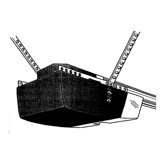
Page 20: Hang The Opener
I Installation Step 6 Hang the Opener Two representative Installations are shown. Yours may be different. Hanging brackets should be angled, Figure 1, to provide rigid support. On finished ceilings, Figure 2, attach a sturdy metal bracketto sh'uctoral Figure I supports before installing the opener. -
Page 21: Install The Door Control And Connect All Wires
Install the Premium Control Console I Installation Step 7 and Connect all Wiring may cause sedans Injuryfrom shock, bumorelectrocution. Locate the door control within sight of the door at a Children o pa_tlngor playing witha garage door opener c an minimum height of 5 feet where small children cannot themselves or others. -
Page 22: Electrical Requirements
Electrical Requirements I Installation Step 8 To reduce the risk of electric shock, your garage door opener has a grounding type plug with a thirdgrounding item. T hisplug will o nly fit into a grounding type outh.q. If the plug doesn't fit into the outlet you have, contact a qualified electrician to install the proper outlet. -
Page 23: Install The Lights And Lens
Instafl the Lights and Lens I Installation Step 10 light • Install a 100 watt maximum bulb in each socket. The lights will turn ON and remain lit for approximately 4-1/2 minutes when power is connected. Then the lights will turn OFF. •... -
Page 24: Fasten The Door Bracket(Sectional Door)
Fasten Door Bracket Follow instructions which apply to your door type I nstallation Step 12 as illustrated below or on page 25. A horizontal brace should be long enough to be secured to 2 vertical supports. A vertical brace should cover the height of the top panel. -
Page 25: Fasten The Door Bracket (One-Piece Door)
All ONE-PIECE Door Installation Procedure Please read and comply with the warnings and reinforcement instructions on page 24. They apply to one-piece doors also. Header Bracket Door Bracket Opt_al placement o_Doo¢ 8racket Fo( a door with no exposed framing or for the opltonal tnstallatton. -
Page 26: Connect Door Arm To Trolley (Sectional Door)
Connect Door Arm to Trolley I nstallation Step 13 Follow instructions which apply to your door type as illustrated below and on page 27. SECTIONAL Doors Only Make sure garage door is fully dosed. Pull the emergency release handle to disconnect the outer trolley from the inner trolley. -
Page 27: Connect Door Arm To Trolley (One-Piece Door)
All ONE-PIECE Doors Assemble the Door Arm: • Fasten the straight and curved door ann sections together to the longest possible length (with a 2 or 3 Lock Washers hole overlap). 5/t6" • With the door closed, connect the straight door arm cl_.s Pin section m the door bracket with the 5/16"x1-1/4"... -
Page 28: Adjustment Section: Pages
ADJUSTMENT SECTION: PAGES 28 - 30 Adjustment Step 1 Adjust the UP and DOWN Limits Do not make any limit adjustments until the safety reversing sensors are completely installed. Limit adjustment settings regulate the points at which the door will stop when moving up or down. If anything interferes with the door's upward travel, it will stop. -
Page 29: Force Adjustments
I Adjustment Step 2 Adjust the Force Toomuchforceon thedoorwillinterfere with theproper operation of the safetyreverse system.The door might Force adjustment controls are located on the fight panel not reverseproperly whenrequired and couldseriously of the opener. Force adjustment settings regulate the injure or killsomeone underiL Donot Increase theforce amount of power required to open and close the door. -
Page 30: Test The Safety Reversing Sensor
Test the Safety Reversing Sensor • Press the remote control push button to open the door. I Adjustment Step 3 • Place the opener carton in the path of the door. • Press the remote control push button to close the door. The door will not move more than an inch, and the opener light will flash for 5 seconds. -
Page 31: Operation Safety Instructions
IMPORTANT SAFETY INSTRUCTIONS To reduce the risk of severe injury or death to persons: 1. READ AND FOLLOW ALL INSTRUCTIONS. 2. Do not permit children either to operate or to play with the opener. Keep remote control in a location inaccessible to children. -
Page 32: Operation Of Your Opener
Operation of Your Opener Activate the opener with any of the following: • The Remote Control: Hold push buttondown until the door startsto move. • The Door Control: Hold push baror buttondown until the door starts to move. • The Outdoor Key Switch or Keyless Entry: (See Accessories) When the opener is activated with the safety reversing... -
Page 33: Receiver & Remote Control Programming
Receiver and Remote Control Programming SECUBlri'T,I; To complywith FCC miss. adjustment o r modifications o f thisr_e_r s_Por tmnsmitter a m I_.l_ted, except_ chan_g me cndeset,rigor Your garage door opener receiver and remote control pAR_ the battery. THERE ARE NO OTHER USER SERViCEABlE have been pre-set at the factory. -
Page 34: Troubleshooting
Troubleshooting Situation Probable Cause & Solution The opener doesn't I. Does the opener have electric power?Plug a lamp into the outlet. If it doesn't fight, check the operate from either fuse box or the circuit breaker.(Some outlets arecontrolled by a wall switch.) the door control or 2. - Page 35 Troubleshooting (continued) Probable Cause & Solution Situation 1. If the opener lights blink, check the safety reversing sensor. See page 22. The door opens but won't close: 2. If the opener fights do not blink and it is a new installation, check the down force. See Adjustment Step 2, page 29.
-
Page 36: Repair Parts,Rail Assembly
Repair Parts Rail Assembly Parts KEY PART NO. NO. DESCRIPTION 41A4796-1 Hardware bag 41A4795 Hardware bag (includes sprocketcoupling) 12B569-1 Left rail bracket 12B569-2 Rightrail bracket 1D4940 Screw drive rail assembly 12B560 Rail support braces (2) 81C168 Rack 41C4677 Complete trolley assembly 25A18 Sprocketcoupling 41A4836... -
Page 37: Repair Parts, Power Unit
Repair Parts Opener Assembly Parts emwn MMIT SWITr._I A_qY. Center _ [Up) _""""'_ Yegow Contact Contact Wire PART PART DESCRIPTION DESCRIPTION 31D426 Drive shaft cover 41A4843 Interruptercup 41A4837 Worm gear and retainer 41B4245 Line cord 41C4669 Wire harness assembly 30B363 Capacitor - 1/2 HP 41C4672 RPM sensor assembly... -
Page 38: Accessories
Accessories Available For Your Opener 139.53702 Emergency Key Release: 139.53681 SECURITY÷ 3-Function Remote Control: Required for a garage with NO access Includes visor clip. door. Enables homeowner to open garage door manually from outside by disengaging trolley. 139.53703 Outdoor Key Switch: 139.53680 SECURITY÷... -
Page 39: Index
Index Access Door/Emergency Key Release Accessory ....................6, 7, 35, 36 Electrical Safety Warnings ............................2, 22, 31 Garage Door Testing for balance, binding and sticking ......................... 3, 28, 31 Determining high point of travel: Sectional door .................................. One-piece door ................................Disabling existing locks .............................. -
Page 40: How To Order Repair Parts
For in-home major brand repair service: Call 24 hours a day, 7 days a week 1 "800-4-MY-HOME = (1-800-469-4663) For the repair or replacement parts you need: Call 7 am - 7 pm, 7 days a week t-800-366-PART (1-800-366-7278) I • For the location of a Sears Parts and Repair Center in your area: Call 24 hour_;a day, 7 days a week t -8OO-488-1 222...
Need help?
Do you have a question about the 139.53963SRT and is the answer not in the manual?
Questions and answers
Can I program a new 2025 car to this garage door opener or is it too old?
The Craftsman garage door opener with part number 139.53963SRT is compatible with Security+ remotes and was produced after 1997. If the 2025 car has a built-in HomeLink system or another garage door remote integration, it may be compatible if it supports Security+ rolling code technology. However, successful programming depends on the car's system compatibility with the opener's technology.
This answer is automatically generated