Table of Contents
Advertisement
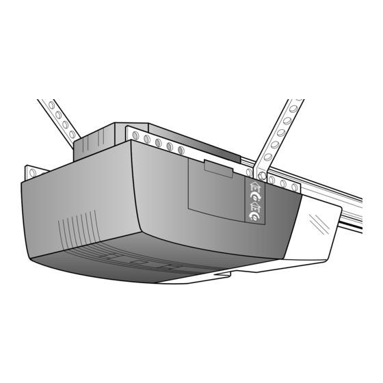
Owner's
Manual
Model No.
139.53663SRT
For Residential Use
Only
Caution:
Read and follow all
safety rules and
operating instructions
before first use of this
product.
Fasten the manual
near the garage door
after installation.
Complies with UL 325
regulations effective
January 1, 1993
®
®
Sears, Roebuck and Co., Hoffman Estates, IL 60179 U.S.A.
GARAGE DOOR OPENER
1/2 HP
Safety Precautions
Assembly
Installation
Adjustment
Care and Maintenance
Operation
Troubleshooting
Parts List
®
®
Advertisement
Table of Contents

Related Manuals for Craftsman 139.53663SRT


Summary of Contents for Craftsman 139.53663SRT
- Page 1 Owner’s Manual Model No. 139.53663SRT For Residential Use Only ® GARAGE DOOR OPENER 1/2 HP Caution: Safety Precautions Read and follow all Assembly safety rules and Installation operating instructions Adjustment before first use of this product. Care and Maintenance Operation...
-
Page 2: Table Of Contents
Contents Safety alert symbol review..........2 Complete the safety reversing sensor installation..22 Safety information, precautions, tools ......3 Install the lights and lens ..........23 Testing your garage door for binding & balance ..3 Attach the emergency release rope and handle..23 Carton inventory ............4 Fasten the door bracket (sectional door) ....24 Hardware inventory............5 Fasten the door bracket (one-piece door)....25... -
Page 3: Safety Information, Precautions, Tools
Safety Information and Precautions; Tools CAUTION WARNING WARNING The Chamberlain Group, Inc. Testing Force Setting An unbalanced gara ge door might not re verse when To avoid damage to the garage door and opener, disable New GDO Manual required and someone under the door could be seriously locks before installing and operating the opener. -
Page 4: Carton Inventory
Carton Inventory Your garage door opener is packaged in one carton which contains the power unit and all parts illustrated below. If anything is missing, carefully check the packing material. Parts may be "stuck" in the foam. KEEP THE FOAM INTACT (see page 10). -
Page 5: Hardware Inventory
Hardware Separate all hardware from the packages in the rail carton and the opener carton and group as shown below, for the assembly and installation procedures. Assembly Hardware Bolt Lock Nut 1/4" - 20 x 5/8" 1/4"-20 x 7/16 (12) Sprocket Coupling Sleeve 1/4-20x1-3/4"... -
Page 6: Illustration Of Sectional Door Installation
SECTIONAL Door Installation Before you begin, survey your garage area to see whether any of the conditions below apply to your installation. FINISHED CEILING Support bracket & fastening hardware is required. Horizontal and vertical reinforcement See page 20. is needed for lightweight garage doors (fiberglass, steel, aluminum, door with glass panels, etc.). -
Page 7: Illustration Of One-Piece Door Installation
ONE-PIECE Door Installation Before you begin, survey your garage area to see whether any of the conditions below apply to your installation. Header One-Piece Door without Track Wall Closed Position Rail Bracket Access Door Rail Assembly The Chamberlain Group, Inc. Header One-Piece Door with Track Installation (Cable -USA) Trolley... -
Page 8: Assembly Section: Pages
ASSEMBLY SECTION: PAGES 8 - 11 Assembly Step 1 To avoid installation difficulties, do not run the garage Assemble the Rail door opener until instructed to do so. Straight Door Arm Extend End Rails Remove Outward Cardboard Packing Rail Center Support Rail Braces... - Page 9 Assembly Step 1 (Continued) Assemble the Rail The Chamberlain Group, Inc. Screw Drive LM 3-Piece Rail 4. Beginning with the sprocket end, straighten the two 7. Keeping the rail straight and on a level surface, grasp Align Rails & Attach Support Brackets rail sections so that the screw rod is in a straight line at the screw rods on each side of the remaining joint and the joint.
-
Page 10: Fasten Rail To Power Unit
Assembly Step 2 Fasten the Rail To the Power Unit The Chamberlain Group, Inc. and Install the Trolley Screw Drive LM 114A1794 Attaching Rail Assembly & Coupling to Chassis 6/9/94 - 6/18/94 - 10/19/9 NOTE: To aid in assembly and installation, replace 12/7/94 the foam packing around the power unit. -
Page 11: Attach The Rail Brackets
Liftmaster Screw Drive #114A1794 6/5/94 - 12/5/94 Assembly Step 3 Attach the Rail Brackets 1/4"-20 • Align rail brackets to end of rail assembly, as shown. Rail Lock Nuts Brackets • Insert two 1/4"-20 x 5/8" hex screws and lock nuts. Tighten securely with a 7/16"... -
Page 12: Installation Section: Pages
INSTALLATION SECTION: PAGES 12 – 27 The Chamberlain Group, Inc. SECTIONAL DOOR AND SECTIONAL DOOR AND Position Header Bracket ONE-PIECE DOOR WITH TRACK Installation Step 1 WARNING Sectional and One-Piece Track Installations ONE-PIECE DOOR WITH TRACK Determine Header Bracket Location 1/30/92 - 4/6/92 If the header bracket is not rigidly fastened to a Installation procedures vary according to garage... -
Page 13: One-Piece Door
One Piece Door Without Track 1/30/92 - 4/7/92 ONE-PIECE Door Without Track Read the Safety Instructions on page 12. They also apply to doors without tracks. Unfinished • Close the door and mark the inside Header Wall Ceiling Vertical vertical centerline of your garage door. Centerline Extend the line onto the header wall above door. -
Page 14: Install The Header Bracket
Installation Step 2 Install the Header Bracket You can attach the header bracket either to the wall above the garage door, or to the ceiling. Follow the instructions which will work best for your particular requirements. Fastening the Header Bracket to the Ceiling Fastening the Header Bracket to the Wall •... -
Page 15: Attach The Rail To The Header Bracket
Installation Step 3 Attach the Rail to the Header Bracket e Chamberlain Group, Inc. am/Rail to Header Bracket ew Rail Assy. • Position the opener on the garage floor below the /6/94 header bracket. Use packing material as a protective base. -
Page 16: Safety Reversing Sensor Information
The Safety Reversing Sensor Information you'll need before you begin the installation of the safety reversing sensor The safety reversing sensor must be connected and WARNING aligned correctly before the garage door opener will move in the down direction. This is a required safety device and cannot be disabled. -
Page 17: Install The Safety Reversing Sensor
Installation Step 4 Install the Safety Reversing Sensor (Receiving and Sending Eyes) Figure 1 Figures 1 and 2 show assembly of brackets and "C" wrap based on the recommended installation of the sensors on Garage WALL or DOOR TRACK Installation each side of the garage door as shown on page 16. - Page 18 Installation Step 4 (Continued) Install the Safety Reversing Sensor 7. Center each sensor unit in a “C”- wrap with lenses Wing "C" Wrap pointing toward each other across the door (see Figure 5). 8. Secure sensors with the hardware shown. Finger Indicator Light The Chamberlain Group, Inc.
-
Page 19: Position The Opener
Liftmaster Screw Drive #114A1794 114A1794 Lift-Master One Piece Rail 5/9/94 - 6/1/94, 6/8/94 - 10/20/94 6/2/94, 6/15 Installation Step 5 5/9/94 - 6/1/94, 6/8/94 - 10/20/94 CAUTION Position the Opener To prevent damage to steel, aluminum, fiberglass or Follow instructions which apply to your door type glass panel doors, do not rest the opener on the door as illustrated. -
Page 20: Hang The Opener
Installation Step 6 WARNING The Chamberlain Group, Inc. Hang the Opener Screw Drive Liftmaster #114A1794 The opener could fall and injure someone if it is not Hang Opener Chassis properl y secured. Fasten the opener securel y to 6/18/94 structural supports of the garage. Two representative installations are shown. -
Page 21: Install The Door Control And Connect All Wires
Installation Step 7 CAUTION WARNING Install the Premium Control Console and Connect all Wiring Do not connect to live electrical wiring. Connect only to 24 Volt low voltage wires. Connection to live wires or higher v oltage may cause serious injury from shock, burn or electrocution. Locate the door control within sight of the door at a Children operating or playing with a garage door opener can minimum height of 5 feet where small children cannot... -
Page 22: Electrical Requirements
STEP 8 Connect Electric Power - Sears 315-699 #2 Installation Step 8 Model5315, 53415, 53515,43625 & 53699 (Yellow Disk #2) WARNING WARNING Electrical Requirements 3/3/89 - 7/25/89 - 8/2/89 - 4/17/92 To prevent electrocution or fire, installation and wiring Right Wrong must be in compliance with local electrical and building To reduce the risk of electric shock, your garage door... -
Page 23: Install The Lights And Lens
Installation Step 10 Install the Lights and Lens 100 Watt Max. Light Bulb • Install a 100 watt maximum light bulb in each socket. The lights will turn ON and remain lit for approximately 4-1/2 minutes when power is connected. Top Lens Slot Then the lights will turn OFF. -
Page 24: Fasten The Door Bracket (Sectional Door)
Installation Step 12 CAUTION Fasten Door Bracket Follow instructions which apply to your door type To prevent damage to steel, alumin um, fiberglass or glass panel doors, always reinforce the inside of the door as illustrated below or on page 25. The Chamberlain Group, Inc. -
Page 25: Fasten The Door Bracket (One-Piece Door)
6/4/94 All ONE-PIECE Door Installation Procedure Please read and comply with the warnings and reinforcement instructions on page 24. They apply to one-piece doors also. Header Wall Finished Ceiling 2x4 Support Horizontal and vertical Header reinforcement is needed for Bracket lightweight garage doors Door (fiberglass, aluminum, steel,... -
Page 26: Connect Door Arm To Trolley (Sectional Door)
Installation Step 13 Connect Door Arm to Trolley Follow instructions which apply to your door type as illustrated below and on page 27. SECTIONAL Doors Only DoorArmTrolleySecScrew 6/96 Make sure garage door is fully closed. Pull the emergency release handle to disconnect the outer trolley from the inner trolley. -
Page 27: Connect Door Arm To Trolley (One-Piece Door)
All ONE-PIECE Doors Assemble the Door Arm: Ring Door • Fasten the straight and curved door arm sections Fastener Bracket together to the longest possible length (with a 2 or 3 Nuts Lock 5/16"-18 hole overlap). Washers 5/16" Ring • With the door closed, connect the straight door arm Door Clevis Pin Straight... -
Page 28: Adjustment Section: Pages
Screw Drive LM 114A1794 ADJUSTMENT SECTION: PAGES 28 – 30 Limit Adjustments 5/4/94, 5/18/94 - 6/5/94 Adjustment Step 1 WARNING Adjust the UP and DOWN Limits Improper adjustment of the travel limits will interfere with Do not make any limit adjustments until the safety the proper operation of the safety reverse system. -
Page 29: Force Adjustments
Adjustment Step 2 WARNING Adjust the Force Too much force on the door will interfere with the proper The Chamberlain Group, Inc. operation of the safety reverse system. The door might Screw Drive LM 114A1794 Force adjustment controls are located on the right panel not reverse properly when required and could seriously of the opener. -
Page 30: Test The Safety Reversing Sensor
Adjustment Step 3 WARNING Test the Safety Reversing Sensor Without a properly working safety reversing sensor, persons (particularly children) could be seriously injured • Press the remote control push button to open the door. or killed if trapped by a closing garage door. Repeat this •... -
Page 31: Operation Safety Instructions
IMPORTANT SAFETY INSTRUCTIONS WARNING WARNING WARNING WARNING To reduce the risk of severe injury or death to persons: 1. READ AND FOLLOW ALL INSTRUCTIONS. 2. Do not permit children either to operate or to play with the opener. Keep remote control in a location inaccessible to children. -
Page 32: Operation Of Your Opener
Operation of Your Opener Trolley Activate the opener with any of the following: WARNING • The Remote Control: Hold push button down until the Trolley Release Arm door starts to move. Emergency • The Door Control: Hold push bar or button down until Release Weak or broken springs could allow an open door to fall Handle... -
Page 33: Receiver And Remote Control Programming
Receiver and Remote Control Programming To comply with FCC rules, adjustment or modifications of this receiver and/or transmitter are prohibited, except for changing the code setting or replacing the battery. THERE ARE NO OTHER USER SERVICEABLE PARTS. Your garage door opener receiver and remote control have been pre-set at the factory. -
Page 34: Troubleshooting
Troubleshooting Situation Probable Cause & Solution 1. Does the opener have electric power? Plug a lamp into the outlet. If it doesn't light, check the The opener doesn't fuse box or the circuit breaker. (Some outlets are controlled by a wall switch.) operate from either the door control or 2. - Page 35 Troubleshooting (continued) Situation Probable Cause & Solution The door opens but 1. If the opener lights blink, check the safety reversing sensor. See page 22. won't close: 2. If the opener lights do not blink and it is a new installation, check the down force. See Adjustment Step 2, page 29.
-
Page 36: Repair Parts, Rail Assembly
Repair Parts Rail Assembly Parts KEY PART NO. NO. DESCRIPTION 41A4796 Hardware bag 41A4795 Hardware bag (includes sprocket coupling) 12B569-1 Left rail bracket 12B569-2 Right rail bracket 1C4827-2 Screw drive rail assembly 12B560 Rail support brace 81C168 Rack 41C4677 Complete trolley assembly 25A18 Sprocket coupling 41A4836... -
Page 37: Repair Parts, Power Unit
Repair Parts e Chamberlain Group, Inc. Opener Assembly Parts ploded View (Down) tmaster Screw Drive LIMIT SWITCH ASSY. Brown Contact Wire 14A1794 1/94 - 7/22/94 Grey Wire Drive Gear Center Limit (Up) Yellow Contact Contact Wire PART PART DESCRIPTION DESCRIPTION 31D426 Drive shaft cover 41A4843... -
Page 38: Accessories
Accessories Available For Your Opener 139.53702 Emergency Key Release: 139.53681 SECURITY 3-Function Remote Control: Required for a garage with NO access Includes visor clip. door. Enables homeowner to open garage door manually from outside by disengaging trolley. SECURITY Compact 3-Function 139.53703 Outdoor Key Switch: 139.53680... -
Page 39: Index
Index Access Door/Emergency Key Release Accessory....................6, 7, 35, 36 Electrical Safety Warnings ............................2, 22, 31 Garage Door Testing for balance, binding and sticking.........................3, 28, 31 Determining high point of travel: Sectional door..................................12 One-piece door ................................13 Disabling existing locks ..............................3, 11 Force controls Adjustment procedures..............................29 Problems that might require force adjustments......................34, 35... -
Page 40: How To Order Repair Parts
For professional installation Call 24 hours a day, 7 days a week 1-800-865-6500 For the repair or replacement parts you need Call 7 am – 7 pm, 7 days a week 1-800-366-PART (1-800-366-7278) For in-home major brand repair service Call 24 hours a day, 7 days a week 1-800-4-REPAIR (1-800-473-7247) For the location of a Sears Repair Service Center in your area...
Need help?
Do you have a question about the 139.53663SRT and is the answer not in the manual?
Questions and answers