Table of Contents
Advertisement
Quick Links
OWNER'S MANUAL
Safety, Assembly, Operating, and Maintenance Instructions
and ILLUSTRATED PARTS MANUAL
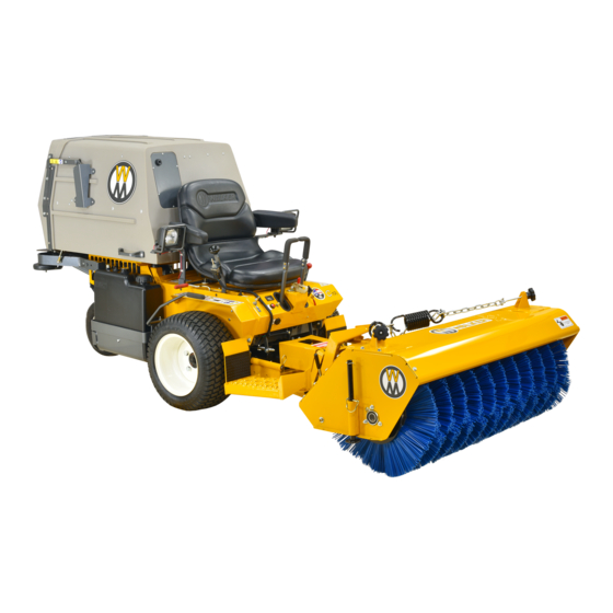
IH6620 Implement Hitch, RB6650 Rotary Broom, DB6660 Dozer Blade,
SB6670 Two-Stage Snowblower and DB6680 Debris Blower
Please Read and Save These Instructions
Effective Date 06-01-01
For Safety, Read All Safety and Operation
P/N I375
Instructions Prior to Operating Machine
Price $5.00
Advertisement
Table of Contents

Related Manuals for Walker DB6660


Summary of Contents for Walker DB6660
- Page 1 OWNER’S MANUAL Safety, Assembly, Operating, and Maintenance Instructions and ILLUSTRATED PARTS MANUAL IH6620 Implement Hitch, RB6650 Rotary Broom, DB6660 Dozer Blade, SB6670 Two-Stage Snowblower and DB6680 Debris Blower Please Read and Save These Instructions Effective Date 06-01-01 For Safety, Read All Safety and Operation P/N I375 Instructions Prior to Operating Machine Price $5.00...
- Page 2 Foreword Thank you. . .for purchasing a Walker implement. Every effort has been made to provide you with the most reliable product on the market, and we are sure you will be among our many satisfied cus- tomers. If for any reason this product does not perform to your expectations, please contact us at (970) 221-5614.
-
Page 3: Table Of Contents
Table of Contents TWO-STAGE SNOWBLOWER ____________ 27 Owner’s Manual Snowblower Assembly ________________ 27 Snowblower Installation _______________ 28 General Information ________________ 1 DEBRIS BLOWER ______________________ 31 Debris Blower Installation______________ 31 HIGHLIGHTED INFORMATION _____________ 1 PREOPERATING CHECKLIST ____________ 32 GLOSSARY ____________________________ 1 Implement Hitch______________________ 32 IDENTIFYING NUMBER LOCATIONS ________ 1 Dozer Blade _________________________ 32... - Page 4 Table of Contents Maintenance Instructions Removal and Storage Instructions __________ 43 _ 68 MAINTENANCE SCHEDULE CHART _______ 43 REMOVAL ____________________________ 68 LUBRICATION _________________________ 44 Removing Attachments Rotary Broom Gearbox ________________ 44 From Implement Hitch_________________ 68 Rotary Broom Drive Chain _____________ 44 Dozer Blade ________________________ 68 Two-Stage Snowblower Gearbox ________ 45 Rotary Broom _______________________ 68...
-
Page 5: General Information
Walker Mower Dealer. There are PTO shield. The dozer blade serial number is af- several general practices to be aware of in the area fixed to the LH side of the hitch box on the back of safety. - Page 6 General Information Serial Number Serial Number Two-Stage Snowblower Serial Number Location (Rear View and RH View) Implement Hitch Serial Number Location (Top View) Serial Number Serial Number Debris Blower Serial Number Location (Rear View and RH View) Dozer Blade Serial Number Location (Rear View) Serial Number Rotary Broom Serial Number Location...
-
Page 7: Servicing Of Drivetrain Gearbox
Two-Stage Snowblower vice Department for assistance: The 42-inch (107 cm) two-stage snowblower Walker Manufacturing Company throws snow up to 40 ft (12 m). It is raised and low- 5925 E. Harmony Road ered automatically with the lift control switch. The... -
Page 8: Specifications
Specifications MODEL IMPLEMENTS IMPLEMENT HITCH Height 10 in. (25 cm) Width 33-1/2 in. (85 cm) Length 30 in. (76 cm) Overall Length Installed on Tractor 69-3/4 in. (177 cm) Weight 70 lb (32 kg) Lift 12 Volt DC Electric Ram Linear Actuator, Operated by Toggle Switch Mounted on FSC Lever DOZER BLADE Height... -
Page 9: Two-Stage Snowblower
Specifications MODEL IMPLEMENTS ROTARY BROOM (continued) Hitch System Patented Quick Hitch System Type Brush 18 in. (46 cm) Diameter Polypropylene or Steel, Clockwise Rotation Brush Drive PTO Shaft Driving Center Mounted Gearbox Primary Reduction Gearbox, 2.78:1 Ratio Secondary Reduction #40 Chain and Sprockets, 3.27:1 Ratio Maximum Brush Speed 260 RPM Broom Angle Adjustment... -
Page 10: Debris Blower
Specifications MODEL IMPLEMENTS DEBRIS BLOWER Height 28-1/2 in. (72 cm) Width 26 in. (66 cm) Length 34-3/4 in. (88 cm) Overall Length Installed on Tractor 102-1/2 in. (260 cm) Weight (With Female Hitch) 130 lb (59 kg) Lift 12 Volt DC Electric Ram Linear Actuator, Operated by Toggle Switch Mounted on FSC Lever Hitch System Patented Quick Hitch System... -
Page 11: Component Identification
Component Identification NOTE: IMPLEMENT HITCH Control Identification shown in Operating Instructions section and in Illustrated Parts Manual. PTO Shield Male Hitch Assembly Male Quick Hitch Latch Footrest Footrest Safety Chain Assembly Linchpin Mounting Mounting Tube Tube Hitch Locking Lever Linear Actuator Linear Actuator Electrical Connector Jam Nut... -
Page 12: Dozer Blade
Component Identification DOZER BLADE Welded Blade Angle Adjustment Pin Trip Spring Trip Spring Lockout Pin Skid Shoe Bracket Hitch Skid Shoe Trip Spring Lockout Bracket Skid Shoe Female Quick Hitch Dozer Blade Rear View and Right Side View (Not Installed) -
Page 13: Rotary Broom
Component Identification ROTARY BROOM Tension Spring Rotary Broom Stopper Housing Ground Contact Knob Pivot Bracket Broom Angle Adjustment Lever Brush Female Hitch Plastic Parking PTO Shaft Wheel Stand Rotary Broom Rear View and Right Side View (Not Installed) -
Page 14: Two-Stage Snowblower
Component Identification TWO-STAGE SNOWBLOWER Deflector Deflector Position Control Knob Hand Guard Chute Chute Rotation Handle Gearbox Support Bracket Auger Gearbox Frame Auger Two-Stage Snowblower Front View and Right Side View (Not Installed) - Page 15 Component Identification Deflector Deflector Position Chute Control Knob Chute Rotation Handle Snowblower Housing Reduction Box Cover Skid Shoe Parallel Bar Skid Shoe Female Quick Hitch PTO Drive Shaft Two-Stage Snowblower Rear View (Not Installed)
-
Page 16: Debris Blower
Component Identification DEBRIS BLOWER Chute Rotation Handle Blower Motor Housing Belt Guard Linchpin PTO Drive Shaft Female Quick Parking Stand Hitch Pivot Wheel Debris Blower Front View and Left Side View (Not Installed) - Page 17 Component Identification Chute Rotation Handle Belt Guard Parking Stand Deflector Position Pins Control Knob Driveline Guard PTO Drive Shaft Rotation Pinions Parking Stand Female Quick Hitch Debris Blower Rear View and Right Side View (Not Installed)
-
Page 18: Safety Instructions
If you have any questions concerning setup, opera- ing is ignored and proper safety precau- tion, maintenance, or safety, please contact your tions are not taken. authorized Walker Mower Dealer or call Walker Manufacturing Company at (970) 221-5614. BEFORE OPERATING WARNING... -
Page 19: Operating
Do not wear loose fitting clothing that could OPERATING get caught in moving parts. Always wear ade- NOTE: Refer to the Walker Rider Lawnmowers quate protective clothing including long pants. OWNER’S MANUAL for safety instructions for Wearing safety glasses, safety shoes, and a operating the tractor. -
Page 20: Maintenance
13. Do not operate across the face of slopes. Use MAINTENANCE extreme caution when changing direction on slopes. Do not attempt to clear steep slopes. NOTE: Refer to the Walker Rider Lawnmowers OWNER’S MANUAL for proper tractor mainte- 14. Never adjust gauge wheels or skid shoes nance procedures. -
Page 21: Safety, Control, And Instruction Decals
The Decal Part Number is listed below and in the Parts Manual; the Decal Location is shown in the Parts Manual. PTO Shield (Walker P/N 7822) Attaching Hitch... - Page 22 (RAD P/N 657503) Lubricate Chain Danger, High Velocity (RAD P/N 661248) (RAD P/N 657804) Keep Hands Out (Walker P/N I396) (RAD P/N 657761) Grease All Points (RAD P/N 6586708) Avoid Serious Injury (RAD P/N 661247) Check Oil Level (RAD P/N 655683)
-
Page 23: Assembly Instructions
IMPORTANT: If the tractor body needs to be raised, the PTO shield must be in the closed or down po- Walker Implements are shipped partially assem- sition and the implement must be in the lowered bled. After uncrating the implement adaptor and/or position. -
Page 24: Implement Hitch Wiring
Assembly Instructions Attach the toggle switch to the mounting brack- Implement Hitch Wiring et, placing the switch terminals toward the front of the mower. Drill five (5) 13/64 in. (5 mm) diameter holes in the tractor, two in the FSC lever and three in the body, as shown in the illustration. - Page 25 Assembly Instructions Complete the wiring by connecting the wiring harness ends to the toggle switch and to the ac- tuator motor of the implement hitch. Wire Harness Actuator Motor Connector Connector Complete Implement Hitch Wiring Move the implement lift switch backward to raise the implement hitch to the UP position.
- Page 26 Assembly Instructions Implement Hitch Wiring Diagram...
-
Page 27: Dozer Blade
Assembly Instructions DOZER BLADE Dozer Blade Assembly Eyebolt Insert the female quick hitch into the hitch box on the blade attachment. Align the single hole at the end of the female quick hitch with the single hole in the hitch box Welded Tab and insert the pivot pin through both holes. -
Page 28: Dozer Blade Installation
Assembly Instructions Adjust the skid shoes to allow the required Linchpin clearance under the blade. Install a skid shoe Female Male Quick pin in each shoe and lock in place with a 4 mm Hitch Hitch x 80 mm hairpin. Refer to ADJUSTMENTS of Dozer Blade Skid Shoes in Maintenance In- structions. - Page 29 Assembly Instructions Male Quick Stand Support Female Hitch Hitch Bracket Hairpin Hitch Locking Lever Parking Stand Prepare Rotary Broom for Installation Attach the female broom driveline half (with Attach Broom to Implement Hitch quick connect yoke) over the male broom driv- eline half.
-
Page 30: Optional Gauge Wheel Installation
Optional tail weights for the various tractor models are avail- Ground Contact Knob able from your Walker dealer or a sandbag or similar weight may be used. Optional Gauge Wheel Installation NOTE: Gauge wheels are required for lawn work or heavy loads. -
Page 31: Two-Stage Snowblower
Assembly Instructions Remove the pin and hairpin from each gauge wheel. Select the required number of spacer sleeves to remain on the bottom portion of the gauge wheels. Refer to ADJUSTMENTS of Rotary Broom Gauge Wheels in Maintenance Instructions. Hand Guard Remove the parking stands and replace them with the gauge wheels. -
Page 32: Snowblower Installation
Assembly Instructions Insert the 1-11/16 in. (43 mm) plastic bushing in- Insert two (2) 5/16 x 1 in. carriage bolts through to the bushing support and place this over the each of the skid shoes from inside the bend. shaft on the rotation worm. Place a flat washer, lock washer, and nut loose- ly on each bolt and place the bolt heads through Install the rotation worm assembly through the... - Page 33 Assembly Instructions Keyway 1/4 x 1/4 x 1-1/4 in. Key Reduction Box Cover Drive Shaft Yoke Bolt Set Screw Reduction Install Reduction Box Cover Shaft Attach the female portion of the hitch to the Attach Drive Shaft Yoke to Reduction Shaft snowblower using one 3/8 x 1 in.
- Page 34 Assembly Instructions Clevis Female Hitch Male Quick Parallel Bar Hitch Clevis Hitch Locking Lever Attach Parallel Bar to Female Hitch Attach Snowblower to Implement Hitch 11. Insert the rotation handle into the rotation worm. Align the holes and lock in place with a 1/4 x 1 in.
-
Page 35: Debris Blower
80 lb (36 kg) of counterweight should be in- Linchpin stalled on the tail of the tractor. Optional tail weights for the various tractor models are avail- able from your Walker dealer or a sandbag or similar weight may be used. Hitch Locking DEBRIS BLOWER... -
Page 36: Implement Hitch
Optional tail weights for the various tractor models are avail- Raise and lower the implement hitch to make sure able from your Walker dealer or a sandbag or the lift switch and linear actuator operate properly. similar weight may be used. -
Page 37: Debris Blower
Assembly Instructions CHECK BROOM ANGLE ADJUSTMENT CHECK CHUTE AND DEFLECTOR • Refer to Angle Adjustment Lever in Operating In- Make sure the chute and deflector are not clogged with snow and/or ice. structions. • CHECK DRIVE CHAIN Turn the chute rotation handle and rotate the chute. -
Page 38: Operating Instructions
Operating Instructions Snow Removal WARNING Rotate Chute Foreign objects in snow may be thrown Clockwise farther than the snow. Use the slowest Rotate Chute brush speed that will perform the job. Counterclockwise Stay aware of the broom discharge direc- tion at all times. Chute Rotation The rotary broom works best on snow depths of Handle... -
Page 39: Engaging The Snowblower
Operating Instructions Engaging the Snowblower DANGER Make sure that the snowblower is clear of snow If the auger strikes a solid object or the and/or ice before engaging the snowblower. machine begins to vibrate abnormally, im- mediately disengage the PTO clutch, stop Make sure that the auger and fan operate freely. -
Page 40: Removing Snow
Operating Instructions • When operating on a slope, reduce speed and use caution to start, stop, and maneuver. Avoid sharp turns or sudden changes in direction. • When blowing through deep snow drifts, let the snowblower work its way through the drifts. For best results, raise the snowblower and remove a top lay- er of snow, then pass through the area a second time to remove the remaining snow. -
Page 41: Debris Blower Controls
Operating Instructions DANGER DO NOT attempt to unclog the snowblow- er or make any adjustments with the trac- Chute Rotation tor engine running. Disengage the PTO Handle clutch, stop the engine, and remove the ignition key. DANGER Chute Rotation Handle NEVER place hands in the blower spout. -
Page 42: Engaging The Debris Blower
Operating Instructions the debris. Orient the blower away from people and Engaging the Debris Blower property due to the possibility of thrown objects. Set the engine throttle at about 1/3 speed. DO • To momentarily increase traction in case the drive NOT attempt to engage the PTO clutch at wheels are slipping, use the lift switch to raise the high engine speeds. -
Page 43: Maintenance Instructions
Maintenance Instructions CAUTION Maintenance procedures requiring special training or tools should be performed by a trained technician. MAINTENANCE SCHEDULE CHART - RECOMMENDED SERVICE INTERVALS - IMPLEMENTS Reference Model Service Item Daily Hours Yearly Page Check Tire Chains (Optional) Check Gauge Wheels or Skid Shoes All Models: Check Tractor Tailweight Lubricate Grease Fittings and Oil Points... -
Page 44: Lubrication
Maintenance Instructions LUBRICATION LUBRICATION If the lubricant is flowing out of the plug hole, the gearbox is full. Reinsert the plug. If no lubricant flows out, add SAE E.P. (Extreme Pressure) WARNING 90W oil into the gearbox through the plug hole until it starts to flow out. -
Page 45: Two-Stage Snowblower Gearbox
Maintenance Instructions LUBRICATION Two-Stage Snowblower Gearbox Two-Stage Snowblower Reduction Chain The gearbox is permanently lubricated (oil filled) and Lubricate the reduction chain every 25 hours. A light sealed requiring no scheduled lubrication. However, penetrating oil or special purpose chain oil is recom- the gearbox oil seal(s) should be checked every 25 mended. -
Page 46: Implement Hitch
Maintenance Instructions LUBRICATION Ident Lubrication Ident Lubrication Location Type Places Location Type Places Implement Hitch Hitch Pivot Shaft Quick Hitch Latch PTO Shield Hinge NOTE: Tractor Lubrication Points are not shown here. Hitch Locking Lever Pivot For Tractor Lubrication Points, refer to the ap- Mounting Tube Sockets Grease Hitch Lift Crank... - Page 47 Maintenance Instructions LUBRICATION Implement Hitch Lubrication Points...
-
Page 48: Dozer Blade
Maintenance Instructions LUBRICATION Ident Lubrication Ident Lubrication Location Type Places Location Type Places Dozer Blade Angle Adjustment Pin Female Quick Hitch Pivot Pin Cutting Edge NOTE: Tractor Lubrication Points are not shown here. Skid Shoe Brackets Grease For Tractor Lubrication Points, refer to the ap- (Grease Slide Area) Hitch Box Pin propriate Tractor OWNER’S MANUAL or IL-... - Page 49 Maintenance Instructions LUBRICATION Dozer Blade Lubrication Points...
-
Page 50: Rotary Broom
Maintenance Instructions LUBRICATION Ident Lubrication Ident Lubrication Location Type Places Location Type Places Rotary Broom Gearboxes are permanently lubricated and Chain Drive Sprocket sealed requiring no scheduled lubrication. Chain Drive Shaft Grease Oil level should be checked only when an oil leak is noted. - Page 51 Maintenance Instructions LUBRICATION Rotary Broom Lubrication Points...
-
Page 52: Two-Stage Snowblower
Maintenance Instructions LUBRICATION Ident Lubrication Ident Lubrication Location Type Places Location Type Places Two-Stage Snowblower Plastic Anti-Friction Insert Grease Chute Knobs Grease Auger Sections Grease Deflector Slide Area Grease Gearbox Gearboxes are permanently lubricated and Cutting Edge sealed requiring no scheduled lubrication. Skid Shoes Grease Oil level should be checked only when an oil... - Page 53 Maintenance Instructions LUBRICATION Two-Stage Snowblower Lubrication Points...
-
Page 54: Debris Blower
Maintenance Instructions LUBRICATION Ident Lubrication Ident Lubrication Location Type Places Location Type Places Debris Blower Rotation Handle Grease Universal Joint Shaft Assembly Grease Front Gauge Wheel Grease (Grease Slide Area) Plastic Anti-Friction Insert Grease Air Blast Nozzle Grease every eight (8) hours. Sprockets NOTE: Tractor Lubrication Points are not shown here. - Page 55 Maintenance Instructions LUBRICATION Debris Blower Lubrication Points...
-
Page 56: Replacing/Repairing
Maintenance Instructions REPLACING/REPAIRING REPLACING/REPAIRING WARNING To prevent accidental engine starting when replacing parts or repairing the machine, remove the key from the ignition switch and disconnect the fuel solenoid wire [diesel engines] or the spark plug wire(s) [gasoline engines]. Reversible CAUTION Cutting Edge ALWAYS use genuine factory replacement... -
Page 57: Rotary Broom Gearbox
Maintenance Instructions REPLACING/REPAIRING Loosen the two sprocket set screws and push Rotary Broom Gearbox sprocket towards the brush. Remove and replace the gearbox as follows: Sprocket Stop the tractor engine, set the parking brake, Chain Chain Idler Idler and remove the ignition key. Bolt Loosen the set screw fastening the driveline fe- male half and slide the driveline off the gearbox... -
Page 58: Rotary Broom Drive Shaft Sprocket
Maintenance Instructions REPLACING/REPAIRING Loosen the bearing flange mounting nuts and Adjust the chain. Refer to ADJUSTMENTS of bolts. Position the chain tension block so that Rotary Broom Drive Chain Tension in this the chain has as much slack as possible. Tight- section. -
Page 59: Two-Stage Snowblower Cutting Edge
Maintenance Instructions REPLACING/REPAIRING Align the slot in the new sprocket with the 10. With the chain installed, recheck the sprocket square key and slide the sprocket onto the drive alignment. shaft. Make sure the key is in place between 11. Lubricate the drive chain. Refer to LUBRICA- the drive shaft and sprocket. -
Page 60: Two-Stage Snowblower Gearbox
Maintenance Instructions REPLACING/REPAIRING Remove the two (2) 5/16-NC nylon locknuts and the two (2) 5/16-NC x 1-1/4 in. hex bolts fasten- ing the support bracket and gearbox to the snowblower frame. Hold and move the gearbox/auger assembly to the left and the right side will slide out. Slide the left side out. -
Page 61: Two-Stage Snowblower Reduction Sprocket
Maintenance Instructions REPLACING/REPAIRING Remove the reduction box cover and reduction chain. Refer to REPLACING/REPAIRING of Master Link Two-Stage Snowblower Reduction Chain in this section. Loosen the set screws that fasten the sprocket to the fan assembly by applying heat to the Plate thread sealant used on these screws during as- sembly. -
Page 62: Debris Blower Rotation Pinions
Maintenance Instructions REPLACING/REPAIRING/ ADJUSTMENTS Loosen the three (3) nuts and three (3) bolts on Adjust the rotation pinions as instructed in AD- lower pulley bearing support and the adjust- JUSTMENTS of Debris Blower Rotation Pin- ment nut on the lower end of each (2) eyebolts ions in this section. -
Page 63: Rotary Broom Brush Leveling
Maintenance Instructions ADJUSTMENTS 1/4 in. (6 mm) Clearance for Level, Paved Surfaces 1/2 to 3/4 in. (13 to 19 mm) Clearance for Uneven or Gravel Surfaces Pivot Bracket Upper Coupler Bolts Skid Shoe Height Adjustment Side to Side Level Adjustment Rotary Broom Brush Leveling Rotary Broom Gauge Wheels IMPORTANT: The proper level adjustment of... -
Page 64: Rotary Broom Drive Chain Tension
Maintenance Instructions ADJUSTMENTS Rotary Broom Drive Chain Tension Two-Stage Snowblower Skid Shoes The drive chain should have 1/4 to 1/2 in. (6 to Adjust the skid shoes to allow the required clear- 13 mm) of slack at midspan. Remove the chain ance under the blade. -
Page 65: Debris Blower Front Gauge Wheel
Maintenance Instructions ADJUSTMENTS Decrease Linchpin Chain Tension Support Box Bolts Pivot Bushing Increase Chain Tension Gauge Wheel Reduction Chain Tension Adjustment Gauge Wheel Height Adjustment Debris Blower Front Gauge Wheel Debris Blower Drive Belt Tension Adjust the gauge wheel height according to surface The drive belt deflection must be 1/8 in. -
Page 66: Debris Blower Rotation Pinions
Maintenance Instructions ADJUSTMENTS Rotation Handle Blower Pulley Bearing Support Bolts Upper Stop Ring & Set Screw Adjustment Eye Bolts Lower Support Drive Belt Tension Adjustment Debris Blower Rotation Pinions Lower Stop Ring The two (2) rotation pinions should slightly contact Rotation &... -
Page 67: Torque Specifications
Maintenance Instructions TORQUE SPECIFICATIONS TORQUE SPECIFICATIONS... -
Page 68: Removal And Storage Instructions
Removal and Storage Instructions REMOVAL Rotary Broom Park the tractor on a level surface and lower the Removing Attachments from Implement rotary broom. Hitch WARNING Dozer Blade Park the tractor on a level surface and lower the DO NOT attempt to remove the rotary dozer blade. -
Page 69: Two-Stage Snowblower
Removal and Storage Instructions PTO Shaft Welded Sleeve PTO Shaft Hairpin Pivot Quick Hitch Lock Pin Lever Hitch Locking Detach Rotary Broom from Implement Hitch Lever Detach Snowblower from Implement Hitch Two-Stage Snowblower Park the tractor on a level surface and lower the Debris Blower snowblower. -
Page 70: Removing Implement Hitch From Tractor
Removal and Storage Instructions PTO Shaft Support Arms Quick Hitch Latch Hitch Locking Parking Lever Stand Detach Implement Hitch from Tractor Detach Debris Blower from Implement Hitch END OF SEASON STORAGE Removing Implement Hitch from Tractor IMPORTANT: Detach any attached implement WARNING from the hitch before detaching the hitch from the tractor. -
Page 71: Rotary Broom
Removal and Storage Instructions NOTE: Rustproofing or painting every year Debris Blower will prolong the life of the blade components and moving parts. Clean the debris blower thoroughly. When the dozer blade is dry, lubricate all mov- Repaint all parts from which paint has worn. ing parts with SAE 30 engine oil. -
Page 72: Implement Hitch Assembly
5830 Grease Fitting NOTE: All NS items are listed with a RAD Part Number (e.g., RAD I393 Decal, Attaching Hitch 657383), and are not sold by Walker Manufacturing. To 3/8-NC Nylon Locknut order these items, contact: I002 Quick Hitch Latch 3/8-NC x 1-1/2 Hex Bolt RAD Technologies Inc. - Page 73 IMPLEMENT HITCH ASSEMBLY ® Effective Date 06-01-01 Use only genuine Walker replacement parts.
-
Page 74: Implement Hitch Electrical Components
Refer to SAFETY, CONTROL, AND INSTRUCTION DECALS in Safety Instructions, Page NOTE: All NS items are listed with a RAD Part Number (e.g., RAD 657383), and are not sold by Walker Manufacturing. To order these items, contact: RAD Technologies Inc. - Page 75 IMPLEMENT HITCH ELECTRICAL COMPONENTS ® Effective Date 06-01-01 Use only genuine Walker replacement parts.
- Page 76 Decal, Stay Clear Blade (RAD 657524) I050 Welded Blade NOTE: All NS items are listed with a RAD Part Number (e.g., RAD 5/16-NC Hex Nut 657383), and are not sold by Walker Manufacturing. To 5/16 Lock Washer order these items, contact: I056 Skid Shoe Pin...
-
Page 77: Dozer Blade Assembly
DOZER BLADE ASSEMBLY ® Effective Date 06-01-01 Use only genuine Walker replacement parts. -
Page 78: Rotary Broom Assembly
7860 Handle Grip Kit is not shown here. May be ordered as a factory-installed option Adjustment Handle (RAD 663640) or as a kit for dealer installation. Contact your Walker dealer. I057 3mm x 65mm Hairpin I306 Stopper Pin, 1/2 x 2-9/16... - Page 79 ROTARY BROOM ASSEMBLY ® Effective Date 06-01-01 Use only genuine Walker replacement parts.
-
Page 80: Rotary Broom Drive Components
Bearing (with Set Screw) NOTE: All NS items are listed with a RAD Part Number (e.g., RAD (Includes Item # F309) 657383), and are not sold by Walker Manufacturing. To 5/16 Lock Washer order these items, contact: 5/16-NC Hex Nut... - Page 81 ROTARY BROOM DRIVE COMPONENTS ® Effective Date 06-01-01 Use only genuine Walker replacement parts.
-
Page 82: Snowblower Housing Components
7/16 ID Flat Washer 3/8 Lock Washer NOTE: All NS items are listed with a RAD Part Number (e.g., RAD 3/8-NC Hex Nut 657383), and are not sold by Walker Manufacturing. To order these items, contact: RAD Technologies Inc. 2835, Chemin de l’Aéroport Thetford Mines (Québec) - Page 83 SNOWBLOWER HOUSING COMPONENTS ® Effective Date 06-01-01 Use only genuine Walker replacement parts.
-
Page 84: Snowblower Drive Components
Decal, Check Oil Level (RAD 655683) NOTE: All NS items are listed with a RAD Part Number (e.g., RAD Decal, Lubricate Chain (RAD 657804) 657383), and are not sold by Walker Manufacturing. To 6671-4 Male Shaft and Yoke Assembly order these items, contact:... - Page 85 SNOWBLOWER DRIVE COMPONENTS ® Effective Date 06-01-01 Use only genuine Walker replacement parts.
-
Page 86: Debris Blower Components
11/32 Nylon Flat Washer (RAD 658467) NOTE: All NS items are listed with a RAD Part Number (e.g., RAD 5/16-NC Nylon Locknut 657383), and are not sold by Walker Manufacturing. To 5/16-NC x 1 Carriage Bolt order these items, contact:... - Page 87 DEBRIS BLOWER COMPONENTS ® Effective Date 06-01-01 Use only genuine Walker replacement parts.
-
Page 88: Debris Blower Manual Rotation Components
I415 Drive Sprocket NOTE: All NS items are listed with a RAD Part Number (e.g., RAD I403 Driven Sprocket 657383), and are not sold by Walker Manufacturing. To I186 1-11/16 Plastic Bushing order these items, contact: 1/4-NC Nylon Locknut Rotation Worm (RAD 663503) RAD Technologies Inc. - Page 89 DEBRIS BLOWER MANUAL ROTATION COMPONENTS ® Effective Date 06-01-01 Use only genuine Walker replacement parts.
- Page 90 NC (Fastner) ........................National Coarse NF (Fastner) .......................... National Fine NPT........................... National Pipe Thread NS (as part number) ..............Item is not sold by Walker Manufacturing N·m .............................Newton-meters O/L ..............Obtain Locally (Item is not sold by Walker Manufacturing) P/N ............................Part Number PPHMS (Fastener) ................
-
Page 91: Warranty
HOW TO OBTAIN SERVICE UNDER THIS WARRANTY: Warranty service can be arranged by contacting the dealer where you purchased the mower or by contacting Walker Man- ufacturing Company, 5925 East Harmony Road, Ft. Collins, CO 80528. Proof of the date of purchase may be required to verify warranty coverage. - Page 92 WALKER MFG. CO. • 5925 E. HARMONY ROAD, FORT COLLINS, CO 80528 • (970) 221-5614 © FORM NO. 060101 PRINTED IN USA 2001 WALKER MFG. CO www.walkermowers.com...
Need help?
Do you have a question about the DB6660 and is the answer not in the manual?
Questions and answers