Advertisement
Quick Links
CR/ FTX
MODEL NUMBER 917.258530
OWNER'S
MANUAL
° Assembly
° Operation
° Customer Responsibilities
° Service and Adjustments
o Repair Parts
CAUTION:
Read and follow all safety rules and instructions
before operating
this equipment.
FOR CONSUMER
ASSISTANCE
HOT LINE, CALL THiS TOLL FREE NUMBER:
1-800-659-5917
Advertisement

Related Manuals for Craftsman EZ3 917.258530


Summary of Contents for Craftsman EZ3 917.258530
- Page 1 CR/ FTX MODEL NUMBER 917.258530 OWNER'S MANUAL ° Assembly ° Operation ° Customer Responsibilities ° Service and Adjustments o Repair Parts CAUTION: Read and follow all safety rules and instructions before operating this equipment. FOR CONSUMER ASSISTANCE HOT LINE, CALL THiS TOLL FREE NUMBER: 1-800-659-5917...
- Page 2 SAFETY RULES Safe Operation Practices for Ride-On Mowers IMPORTANT: THIS CUTTING MACHINE IS CAPABLE OF AMPUTATING HANDS AND FEET AND THROWING OBJECTS, FAILURE TO OBSERVE THE FOLLOWING SAFETY INSTRUCTIONS COULD RESULT IN SERIOUS INJURY OR DEATH_ Ill. CHILDREN GENERAL OPERATION •...
- Page 3 EQUIPMENT For two (2) years from the date of purchase, if this Craftsman Riding Equipment is maintained, lubricated and tuned up according to the instructionsin the owner's manual, Sears will repair or replace, free of charge, any parts found to be defective in material or workmanship.
- Page 4 TABLE OF CONTENTS SAFETY RULES ............OPERATION ............10-15 MAINTENANCE SCHEDULE ........16 PRODUCT SPECIFICATIONS ........3 SERVICE AND ADJUSTMENTS ......2%26 CUSTOMER RESPONSIBILITIES ..... 3, 16-20 STORAGE ..............WARRANTY ..............TROUBLESHOOTING ..........28-29 TABLE OF CONTENTS ..........4 INDEX ................REPAIR PARTS - TRACTOR .........
- Page 5 ACCESSORIES AND ATTACHMENTS These accessories and attachments were available through most Sears retail outlets and service centers when the tractor was purchased, Most Sears stores can order these items for you when you provide the model number of your tractor, ENGINE MAINTENANCE AIR FILTER...
- Page 6 NTS OF HARDWARE PACK ...... ,,,,,,,,,,,,,,, ........Parts ....1 ..' ..Parts packed separately in carton Bag contents shown full size ....i1,1111111111,111111 ....i ii IIIIIIIlUlIII I (1) Hex Bolt 3/8-!6 x I Seat Mulcher Plate...
- Page 7 ASSEMBLY Your new tractor has been assembled at the factory with exception of those parts left unassembled for shipping purposes, To ensure safe and proper operation of your tractor all parts and hardware you assemble must be tightened securely the correct tools as necessary to insure proper tightness, TOOLS REQUIRED FOR ASSEMBLY...
-
Page 8: Product Specifications
....Ulll ......ii iiii ii iiii ASSEMBLY ....,,,,,,.,, • Slide seat until a comfortable position is reached which • Connect BLACK grounding cable to negative (-) termi- allows you to press clutch/brake pedal all the way nal with remaining hex bolt, flat washer, lock washer + down+ and hex nut+ Tighten securely. - Page 9 ASSEMBLY TO CONVERT TO BAGGING GAUGE WHEEL DISCHARGING MOUNTING BRACKET Simply remove mulcher plate and store in a safe place. Your mower is now ready for discharging or installationof optional grass catcher accessory. DEFLECTOR SHIELD FIG. 5 LATCH HOOKS INSTALL MULCHER PLATE (See Figs.
- Page 10 OPERATION ....in,ln,i llll,i i llll These symbols may appear' on your tractor or in literature supplied with the product. Learn and understand their meaning, BATTERY CAUTION OR FORWARD FAST SLOW REVERSE WARNING ENGINE ON ENGINE OFF OIL PRESSURE CLUTCH LIGHTS ON LIGHTS OFF...
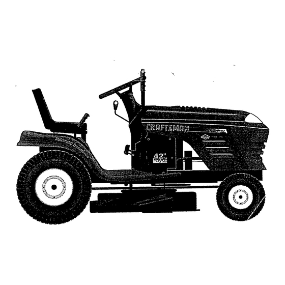
- Page 11 OPERATION KNOW YOUR TRACTOR READ THIS OWNER'S MANUAL AND SAFETY RULES BEFORE OPERATING YOUR TRACTOR Compare the illustrationswith your tractor to familiarizeyourself with the locations of various controls and adjustments_ Save this manual for future reference. ATTACHMENT IGNITION CLUTCH LEVER SWITCH LIGHT SWITCH AMMETER...
- Page 12 The operation of any tractor can result in foreign objects thrown into the eyes, which can result in severe eye damage. Always wear safety glasses or eye shields while operating your tractor or performing any adjustments or repairs. We recommend a wide vision safety mask over the spectacles or standard safety glasses.
- Page 13 i,,i, i iiii Jllllllll, iiiii iiiiii illl illl Hmll OPERATION IMPORTANT: THE MOTfON CONTROL LEVER DOES TO OPERATE MOWER (See Fig. 10) NOT RETURN TO NEUTRAL (N) POSITION WHEN THE Your tractor is equipped with an operator presence sens- CLUTCH/BRAKE PEDAL IS DEPRESSED+ ing switch+ Any attempt by the operator to leave the seat °...
-
Page 14: Carburetor
OPERATION ADD GASOLINE Move motion controlleverto neutral (N) position°Shub Fill fuel tank° Use fresh, clean, regular' unleaded off engine and set parking brake. gasolinewith a minimum of 87 octane. (Use of leaded ° Engage transmission by placing freewheel control in gasoline will increase carbon and lead oxide deposits driving position(See "TO TRANSPORT' inthis section and reduce valve life). - Page 15 OPERATION • Allow one minute for transmission to warm up. MULCHING MOWING TIPS This can be done during the engine warm up period. IMPORTANT: FOR BEST PERFORMANCE, KEEP FREE OF MOWER HOUSING BU1LT-UP GRASS • The attachments can also be used during the engine TRASH°...
- Page 16 Replace Oil Filter (If equipped) ....clean Engine CoolingFIns Replace Spark Plug • Replace Air Ffltet Paper Cartridge Replace Fuet Ftfter ..1 - Change mere often when operating under a heavy load or in high embtent temperatures 5 -if equipped w_thadjustable system, 2 - Service mere often when operating in dirty or dusty conditions.
- Page 17 CUSTOMER RESPONSIBI ..ii ill, llllll TRACTOR MANDREL BLADE Always observe safety rules when performing any mainte- nanceo BRAKE OPERATION If tractor requires more than six (6) feet stopping distance at high speed {nhighest gear, then brake must be adjusted, (See 'q_O ADJUST BRAKE"...
- Page 18 t" BA'I'rERY NOTE: Although multFviscosity oils (5W30, 10W30 etc.) improve starting in cold weather, these multi-viscosity oils Your tractor has a battery charging system which is suffi- will result in increased oil consumption when used above cient for normal use. However, periodic charging of the 32°F.
- Page 19 CUSTOME NSIBILITIES AIR FILTER (See Fig. 18) CLEAN AIR SCREEN (See Fig. 19) Your engine will not run properly using a dirty air filter° Air screen must be kept free of dirt and chaff to prevent Clean the foam pre-cleaner after every 25 hours of opera- engine damage from overheating.
- Page 20 MUFFLER CLAMP inspect and replace corroded muffler and spark arrester (if equipped) as it could create a fire hazard andlor damage. SPARK PLUGS Replace spark plugs at the beginning of each mowing season or after every 100 hours of operation, whichever occurs first.
- Page 21 i ii ,ll,llllll ii,i ,11 ,,llll,lll,ll,lll,,llllll,ll ii,l/i, i llJl,ll, l,/,i,i ........SERVICE AND ADJUSTMENTS CAUTION: BEFORE PERFORMING ANY SERVICE OR ADJUSTMENTS: Depress clutch/brake pedal fully and set parking brake. Place motion control lever in neutral (N) position. Place attachment clutch in "DISENGAGED" position.
-
Page 22: Side-To-Side
..llllli,u _ ,,, i i H,u roll ..... : ..i _,_,l,,i i ....SERVICE D ADJUSTMENTS TO LEVEL MOWER HOUSING FRONT_TO-BACK ADJUSTMENT (See Figs. 24 and 25) IMPORTANT" DECK MUST BE LEVEL SIDE-TO-S1DEo IF Adjust the mower while tractor is parked on level ground or THE FOLLOWING FRONT-TO-BACK ADJUSTMENT IS driveway. - Page 23 SERVICE AND ADJUSTMENTS WITH PARKING BRAKE "ENGAGED" TO REPLACE MOWER BLADE DRIVE BELT NUT "A" (See Fig. 26) The mower blade drive belt may be replaced withouttools, Park the tractor on level surface. Engage parking brake. BELT REMOVAL- • Remove mower from tractor (See 'q'O REMOVE MOWER"...
- Page 24 AND ADJUSTMENTS TO REMOVE WHEEL FOR REPAIRS TO ADJUST MOTION CONTROL LEVER (See Fig. 29) (See Fig. 30) The motion control lever has been preset at the factory and Block up axle securely. adjustment should not be necessary° ° Remove axle cover, retaining ringand washersto allow wheel removal (rear wheel contains a square key- Do If for any reason the motion control lever will not hold its not lose),...
- Page 25 AND ADJ USTMENT POSITIVE TERMINAL NEGATIVE TERMINAL HOOD CABLES FIG. 32 CHARGED BATTERY ENGINE POSITIVE TERMINAL NEGATIVE TERMINAL TO ADJUST THROTTLE CONTROL CABLE (See Fig. 33) FIG. 31 The throttle control has been preset at the factory and adjustment should not be necessary. Check adjustment as TO REPLACE HEADLIGHT BULB...
-
Page 26: Throttle Control Cable
RVICE A ADJUSTMENTS TO ADJUST CARBURETOR (See Fig. 34) ACCELERATION TEST - The carburetor has been preset at the factory and adjust- • Move throttle control lever from slow (,_!) to fast (4) merit shouEd not be necessary. However', minor adjust- position. -
Page 27: Storage
ENGINE Immediately prepare your tractor for storage at the end of the season or if the tractor will not be used for 30 days or more, FUEL SYSTEM IMPORTANT: IT IS IMPORTANT TO PREVENT GUM CAUTION: Never store the tractor with DEPOSITS FROM FORMING IN ESSENTIAL... - Page 28 TROU DOTING POINTS ....,', _,,_,,,,,, = i=l== i ill ii =l=l ....: .... PROBLEM CAUSE CORRECTION Will not start 1,, Out of fuel Fill fuet tank. See "TO START ENGINE" in Operation section Engine not"CHOKED" properly. Eng{ne floodedv 3_ Wait several minutes before attempting to start.
- Page 29 TROUBLESHOOT! POINTS ii ]llll,ll,i/ ii i i ll,lll,,_,_ ......_ ........PROBLEM CAUSE CORRECTION i lllll,,,,,,,,uiill Engine continues to run Faulty operator-safety presence con!rot system, Check wiring, switches and connections, If not corrected, contact an authorized service centart when operator !eaves seat with attachment clutch department,, engaged...
- Page 30 SERVICE NOTES...
- Page 31 TRACTOR - - MODEL NUMBER 917.258530 SCHEMATIC BtACK BATTERY FUSE30 AMP, STARTER AMMETER r---t BLACK ', O', ..WHITE SOLENOID RE__2L " CLUTCH1 BRAKE (PEDAL UP) WHITE SEAT SWITCH IGNITION (NOT OCCUPIED) SWITCH WHITE BLACK L_ l GROUNDING "_ HOUR"t.,--, I"...
- Page 32 REPAIR PARTS TRACTOR - - MODEL NUMBER 917.258530 ELECTRICAL aT_Jr_...
- Page 33 REPAIR PARTS TRACTOR-- MODEL NUMBER 917.258530 ELECTRICAL PART DESCRIPTION 146139 Battery 12 Volt 25 Amp 747604!2 Bolt, Hex Head 1/4-20 unc x 3/4 STD551025 Washer STD551125 Washer STD541025 109238X Tube, Plastic, 12" 156417 Case, Battery Mech Hinge 109596X Clamp, Hose 153684 Switch, {nterlock Push-In STD551125...
- Page 34 REPAIR PARTS TRACTOR -- MODEL NUMBER 917.258530 CHASSIS ENCLOSURES 38_3...
- Page 35 REPAIR PARTS TRACTOR - - MODEL NUMBER 917.258530 CHASSIS AND ENCLOSURES PART DESCRIPTION 153871 Chassis Assembly 140356 Drawbar 17490612 Screw, Thd. Roll. 3/8-16 x 3/4 19131216 Washer 13/32 x 3/4 x 16 Gauge 155272 Bumper Hood/Dash 150156)(011 Dash STD533710 Bolt, Carriage 3/8-16 x 3/4 "146956 Panel, Dash, L.H.
- Page 36 REPAIR PARTS TRACTOR - - MODEL NUMBER 917.258530 DRIVE •:"_ 98 84100...
- Page 37 REPAIR PARTS TRACTOR - - MODEL NUMBER 917.258530 DRIVE PART PART DESCRIPTION DESCRIPTION Pulley, Engine 150071 Transaxle Assembly 140186 Bolt 7/16-20 X 4 Gro 5 142431 Spring, Return, Brake 71170764 143995 PuIley, Transaxle STD551143 Washer Lock Hvy HIcl Spr 7/16 154792 Rod Shift Fender 154778...
- Page 38 REPAIR PARTS TRACTOR - - MODEL NUMBER 917,258530 STEERING ASSEMBLY i-L-: ,,÷ 29"...
- Page 39 REPAIR PARTS TRACTOR - - MODEL NUMBER 917.258530 STEERING ASSEMBLY PART DESCRIPTION 139768 Steering Wheel 154427 Axle Assembly STMP Dropped STL 154422 Spindle Assembly, Loll. 154423 Spindle Assembly, R.H. 6266H Bearing, Race, Thrust, Hardened 121748X Washer 25/32 x 1-5/8 x 16 Gauge 19272016 Washer 27/32 x 1-1/4 x 16 Gauge 12OO0029...
- Page 40 REPAIR PARTS TRACTOR - - MODEL NUMBER 917,258530 SEAT ASSEMBLY PART PART DESCRIPTION DESCRIPTION 140123 Seat 134300 Spacer, Split _28 x .88 140551 Bracket, Pivot, Seat 121250X Spring STD523710 Bolt 123976X Locknut, Flange 1/4 Grade 5 19131610 153236 Bolt, Shoulder 5/16-t8 UNC Washer 13/32 x 1 x 10 Gauge 145006 STD541431...
- Page 41 Decal, Lift Handle 156787 Decal, Deck Mower EZ3 142341 Decal, Drawbar Cntrl Mvt Hyd LT 146709 154515 Pad Footrest LH STLT Decal, Fender, Craftsman 156439 154516 Pad Footrest RH STLT Decal, Fender Danger 146046 Decal, V-Belt Drive Schematic 156788 Owner's Manual, English...
- Page 42 REPAIR PARTS TRACTOR = - MODEL NUMBER 917.258530 ENGINE OPTIONAL EQUIPMENT Spark Arrester...
- Page 43 REPAIR PARTS TRACTOR -- MODEL NUMBER 917.258530 ENGINE PART DESCRIPTION 150600 Control, Throttle 1772041O Screw, Hex Head, Thread Cutting 1/4-20 x 5/8 Engine (See Breakdown) Briggs Model 28N707-0173-01 137352 Muffler 272293 Gasket, Exhaust 1328O324 Nipple, Pipe 3t8 NPT x 3 t3200300 Elbow, Standard 90 °, 3/8-18 NPT STD551237...
- Page 44 REPAIR PARTS TRACTOR =- MODEL NUMBER 917.258530 MOWER LIFT 161718...
- Page 45 REPAIR PARTS TRACTOR - - MODEL NUMBER 917.258530 MOWER LIFT PART DESCRIPTION 136973 Lift Lever Inner Wire Assembly 1451t7 Shaft Assembly, Lift 105767X Pin, Groove 12000002 E-Ring 192t162! Washer 21/32 x 1 x 2! Gauge 120183X Bearing, Nylon 125631X Grip, Handle, Fluted 122365X Button, Plunger, Red 122512X...
- Page 46 REPAIR PARTS TRACTOR - - MODEL NUMBER 917.258530 MOWER DECK 105 ._''104 58 35 113 111 .116 _p_7/_129 92_@_. 3 "_ 13_- / _/. 9---_...
- Page 47 REPAIR PARTS TRACTOR - - MODEL NUMBER 917.258530 MOWER DECK PART PART DESCRIPTION DESCRIPTION 140086 144393 Mower Housing Spring, Torsion Brakes STD533t07 Bolt 141043 Guard, TUV Idler 149846 Knob Custom Oval 138017 Bracket Assembly,Sway Bar, Front V_Belt 144200 138440 Bracket Assembly, Sway Bar STD624008 142427 Rod, Clutch, Primary, with Nibs...
- Page 48 REPAIR PARTS TRACTOR - - MODEL NUMBER 917.258530 HYDRO GEAR TRANSAXLE - MODEL NUMBER 310-0650 _3 52 ''--. "_13...
- Page 49 REPAIR PARTS TRACTOR - - MODEL NUMBER 917.258530 HYDRO GEAR TRANSAXLE - MODEL NUMBER 310-0650 KEY PART KEY PART NO, NO. DESCRIPTION NO. NO. DESCRIPTION 142930 Housing, Lower 142884 Washer 7/16 x 7/8 x °060 !42931 Assembly, Upper Housing 150829 DifferentialAssembly 142932 Seal, Lip...
- Page 50 REPAIR PARTS TRACTOR - - MODEL NUMBER 917.258530 BRIGGS & STRATTON ENGINE - MODEL NUMBER 28N707, TYPE NUMBER 0173-01 _614 634A "h"REQUIRES SPECIAL TOOLS TO INSTALL. SEE REPAIR INSTRUCTION MANUAL. 1022 868A 1034 1029 1023 1026...
- Page 51 REPAIR PARTS TRACTOR - - MODEL NUMBER 917.258530 BRIGGS & STRAI-I'ON ENGINE - MODEL NUMBER 28N707, TYPE NUMBER 0'173-0'1 106 987 634B 1_47 1033 VALVE OVERHAUL REQUIRES SPECIAL TOOLS TO INSTALL, SEE REPAIR INSTRUCTION MANUAL,...
- Page 52 REPAIR PARTS TRACTOR - - MODEL NUMBER 917.258530 BRIGGS & STRATTON ENGINE - MODEL NUMBER 28N707, TYPE NUMBER 0173-01 634A 868 868A 358 'GASKET SET ....... i]1 iiii IlUll 977 CARBUREI'OR GASKET _224 305_ 1006...
- Page 53 REPAIR PARTS TRACTOR -- MODEL NUMBER 917.258530 BRIGGS & STRATTON ENGINE - MODEL NUMBER 28N707, TYPE NUMBER 0173-01 '77_ ..1090...
- Page 54 REPAIR PARTS TRACTOR - - MODEL NUMBER 917.258530 BRIGGS & STRATTON ENGINE - MODEL NUMBER 28N707, TYPE NUMBER 0173-01 KEY PART KEY PART NOo NO. DESCRIPTION NO. NO. DESCRIPTION 94098 496412 Cylinder Assembly ** Screw, Throttle 399265 495800 Screw, Idle Speed •...
- Page 55 REPAIR PARTS TRACTOR - - MODEL NUMBER 917.258530 BRIGGS & STRATTON ENGINE - MODEL NUMBER 28N707, TYPE NUMBER 0173-O1 KEY' PART KEY PART NO. NO. DESCRIPTION NO. NO. DESCRIPTION 284A 94073 Screw, Hex Head 729A 225170 Retainer, Wire 294 810068 Screw, Set 741 262932 Gear, Timing...
- Page 56 ,ill illll illl ii ii i llll i i illlll illl illll ..... illlllll ii ii SERVICE NOTES iiii IIIlUll iiiii IIII ..... , ,,, ii ii ii iHi,i llllll...
- Page 57 ..... ,,,,, ii_l. iillllllllllll i i,ii ii IH ......... , H HHH,., I I H IlllH SERVICE NOTES Illllll Illll...
- Page 58 ..illlllll ..illllllll i iiill E NOTES IIIII IIIIII IIII IIIII...
- Page 59 SUGGESTED GUIDE FOR SiGHTiNG SLOPES FOR SAFE OPERATION ONLY RIDE UP AND DOWN HILL, NOT ACROSS HILL SIGHT AND HOLD THIS LEVEL WITH SKY LINE OR TREE. 15° MAX. IIHI Illlllllllllll Illll III II Operate your Tractor up and down the face of slopes (not _! _ greater than 15°), never across the face.
-
Page 60: Replacement
£RRFTSM IN® 15.5 HP MANUAL ELECTRIC START 42" MOWER AUTOMATIC (HYDROSTATIC) LAWN TRACTOR MODEL NO. Each tractor has its own model number, Each engine has its own model number_ 917.258530 The model number for your tractor will be found on the model pFate located under the seat.
Need help?
Do you have a question about the EZ3 917.258530 and is the answer not in the manual?
Questions and answers