Advertisement
Quick Links
till/F rSMnN°
MODEL NUMBER 917.258861
OWNER'S MANUAL
o Assembly
Operation
Customer Responsibilities
o Service and Adjustments
Repair Parts
....... CAUTION:
Read and folloW all safety ruleS and instructions
before
op-_t_tting thiS equipment:
"
FOR CONSUMER ASSISTANCE HOT LINE, CALL THIS TOLL FREE NUMBER: 1-800-659-5917
IIIllllllllllllllllllll
I IIIII
I
Advertisement

Related Manuals for Craftsman EZ3 917.258861


Summary of Contents for Craftsman EZ3 917.258861
- Page 1 till/F rSMnN° MODEL NUMBER 917.258861 OWNER'S MANUAL o Assembly Operation Customer Responsibilities o Service and Adjustments Repair Parts ..CAUTION: Read and folloW all safety ruleS and instructions before op-_t_tting thiS equipment: " FOR CONSUMER ASSISTANCE HOT LINE, CALL THIS TOLL FREE NUMBER: 1-800-659-5917 IIIllllllllllllllllllll I IIIII...
- Page 2 SAFETY RULES Safe Operation Practices for Ride-On Mowers IMPORTANT: THIS CUTTING MACHINE IS CAPABLE OF AMPUTATING HANDS AND FEET AND THROWING OBJECTS, FAILURE TO OBSERVE THE FOLLOWING SAFETY INSTRUCTIONS COULD RESULT IN SERIOUS INJURY OR DEATH GENERAL OPERATION CHILDREN • Road, understand, and follow all instructions in the manual Tragic acc(dents can occur if the operator is not alert to the and on the machine before starting.
- Page 3 ON CRAFTSMAN RIDING EQUIPMENT For two (2) years from the date of purchase, if this Craftsman Riding Equipment is maintained, tubdcated and tuned up according to the instructions in the owner's manual, Sears will repair or replace, free of charge, any parts found to be defective in materiat or workmanship.
- Page 4 TABLE OF CONTENTS SAFETY RULES ....;........... MAINTENANCE SCHEDULE ........SERVICE AND ADJUSTMENTS ......21-27 PRODUCT SPECIFICATIONS ........STORAGE ..............CUSTOMER RESPONSIBILITIES ..... 3, 17-20 TROUBLESHOOTING ..........29-30 WARRANTY ..............REPAIR PARTS - TRACTOR ......... 32-49 TRACTOR ACCESSORIES .......... REPAIR PARTS - ENGINE ........50-59 ASSEI_BLY ..............
-
Page 5: Accessories
ATTACH M NTS ,llllll ,,111............. These accessories and attachments were availabIe through most Sears retail outlets and service centers when the tractorwas purchased. Most Sears sto_es can order these items for you when you provide the model number of your tractor. MAINTENANCE ENGINE SPARK PLUG... - Page 6 •- i ,u lU ,i ..i,iiiii u, ,, ii i,,u ..i1,,,,11 CONTENTS OF HARDWARE PACK ..u ,, m-lmr i,, ll...mHi, lllllllll I' ill i,i Parts Bag contents shown full size Parts packed separately in carton _Lu_ i,, ,,m,i u H 'M,',,'I ..
- Page 7 ASSEMBLY Your new tractor has been assembled at the factory with the exception of those parts left unassembled for shipping purposes° To ensure safe and proper operation of your tractor all parts and hardware you assemble must be tightened securely. Use the correct tools as necessary to insure proper' tightness.
- Page 8 =,q., = = ,,= ,= mu,= ..m-=, i n ,= i ..mmii-,n= HOW' TO SET UP YOUR TRACTOR INSTALL SEAT (See Fig. 3) Adjust seat before tightening adjustment knob,, CONNECT BATTERY (See Fig. 2) • Remove cardboard packing on seat pan. =m===a_ ............
- Page 9 N==, INHI HI= Hm, ASSEMBLY =H H,m LJlIJ Place the R.H. suspension arm on inward pointing INSTALL MOWER AND DRIVE BELT (See ° deck pin., If necessary, rock and raise front of mower Figs. 4 and 6) to align deck pin with the hole in suspension arm.
- Page 10 CHECK TIRE PRESSURE DEFLECTOR SHIELD The tires on your' tractor we re overJnflated at the factory for shipping purposes. Correct tire pressure is important for best cutting performance. • Reduce tire pressure to PSI shown in "PRODUCT SPECIFICATIONS" on page 3 of this manual. CHECK BRAKE SYSTEM After you ]earn how to operate your' tractor, check to see...
- Page 11 OPERATION These symbols may appear on your product or in!iterat.ure supplied with the product. Learn and understand their meaning. E:3& BATTERY CAUTION OR REVERSE FORWARD FAST SLOW WARNING ENGINE ON ENGINE OFF OIL PRESSURE CLUTCH LIGHTS ON LIGHTS OFF !\l m DIFFERENTIAL PARKING BRAKE UNLOCKED...
- Page 12 ,,, m.==- I,I,,H ..OPERATION KNOW YOUR TRACTOR READ THiS OWNER'S MANUAL AND SAFETY RULES BEFORE OPERATING YOUR TRACTOR Compare the illustrations with your tractor'to familiarize yourself with the locations of vadous controls and adjustments_ Save this manual for' future reference. ATTACHMENT CLUTCH SWITCH...
- Page 13 ,lUUlHI,IHII I n,m=n== = U =' ='=ram'=" I" inln OPERATION =l,==u===lul,l=lu=,, ,,i,ii, luuu,ii Tile operation of any tractor can result in_f0reign objects thrown into the eyes, which can result in severe eye damage° Always wear safety glasses or eye shields while operating your tractor or performing any adjustments or repairs= We recommend a wide vision safety mask over the spectacles or standard safety glasses.
- Page 14 ....• , ...... i, "N"IHII L_"ll'l"l'll,' " II..I" OPERATiO TO OPERATE ON HILLS TO ADJUST GAUGE WHEELS (See Fig. 8) Gauge wheels are properly adjusted when they are slightly CAUTION: Do n0t_ off the ground when mower is at the desired cutting height hills with slopes greater than 15 °...
-
Page 15: Carburetor
..IHHUU Ul ........• OPERATI ..........cO w H ..ADD GASOLINE EAT ER STARTING (50 ° F and below) • Fill fuel tank, Use fresh, clean, regular unleaded When engine starts, slowly push choke control in until gasoline with a minimum of 87 octane.. (Use of leaded the engine begins to run smoothly. - Page 16 OPERATION MULCHaNG MOWING TIPS IMPORTANT: FOR BEST PERFORMANCE, KEEP MAX 1/3 MOWER HOUSING FREE OF BUILT-UP GRASS AND TRASH CLEAN AFTER EACH USE The special mu_ching blade will recut the grass clip- pings many times and reduce them in size so that as they fall onto the lawn they wilt disperse intothe grass and not be noticed.
- Page 17 iiiiiiiii iiiii ,i iii ,llllllll iii CUSTOM RESPONSIBILITIES /___.._r FILL IN DATES AS COMPLETE REGULAR RV,CE DATES Check Brake Operation ....tf Check Tire Pressure v', ..Check for Loose Fasteners Sharpen/Replace Mower Blades Lubrication chart Check Battery Level/Recharge Clean Battery and Terminals v"...
- Page 18 CUSTOM LITtES .., Ull,ii ..i1,1 ,! ,..Ul ....TRACTOR The blade can be sharpened with a file or on a grinding wheel, Do not attempt to sharpen while on the mower_ Always observe safety rules when performing any mainte- nance_ •...
- Page 19 i = i IIINII ,III=III=,INIII,III= N,H=,,NII== CUSTOMER RESPONSIBiLITiES TO CHANGE ENGINE OIL (See Fig. 16) BAKERY Determine temperature range expected before oil change. Your tractor has a battery charging system which is suffi- All oil must meet API service classification SF, SG.or SH cient for normal use.
- Page 20 CUSTOM PONSIBILJTIES i,,i,,,, ,....... ,.., i, i,iiii CLEAN AIR SCREEN (See Fig. 17) WING NUT Air screen must be kept free of dirt and chaff to prevent engine damage from overheating Clean with a wife brush or compressed air to remove dirt and stubborn dried gum CARTRIDGE '___ .LATE...
- Page 21 SERVICE AN ADJUSTMENTS ......_IL'HH_L'I//, '1",,', ,,i,,, ,i _,_,,,i,1,, i ..CAUTION: BEFORE PERFORMING ANY SERVICE OR ADJUSTMENTS: Depress clutcWbrake pedal fully and set parking brake. Place gearshift lever in neutral (N) position. Place attachment clutch in ='DISENGAGED" position. Turn ignition key "OFF" and remove key. Make sure the blades and all moving parts have completely stopped.
-
Page 22: Clutch Pulley
.._ ....,......i ¸ in,ll ,T ... " ,,," ,""," , ..... i,,, SERVICE AN ADJUSTMENTS .._, ,, i ,111, , ii , i, ,i, ,,i, TO REPLACE MOWER DRWE BELT FRONT-TO-BACK ADJUSTMENT (See Figs, 22 and 23) - IMPORTANT;... - Page 23 HHHH='=HI SERVICE AN ADJUSTMENTS TO REPLACE MOWER BLADE DRIVE BELT NOTE: After installing a new electric clutch, run tractor at (See Fig. 25) full throttle and engage and disengage electric clutch 10 cycles to wear in clutch plate. Park the tractor on level surface° Engage parking brake, •...
- Page 24 TO ADJUST STEERING WHEEL ALIGNMENT TO REPLACE MOTION DRIVE BELT tf steering wheel crossbars are not horizontal (left to right) (See Fig. 28) when wheels are positioned straight forward, remove steer- Park the tractor on level surface. Engage parking brake_ lng wheel and reassemble per instructions in the Assembly For ease of service there is a belt installation guide decal on section of this manual..
- Page 25 TO REMOVE CABLES, REVERSE ORDER - TO REMOVE WHEEL FOR REPAIRS ° BLACK cable first from chassis and fully charged FRONT WHEEL (See Fig_ 31) - battery° Block up axle securely, • RED cable last from both batteries. ° Remove axle cover, retaining ring and washers to allow wheel removal.
- Page 26 SERVICE AND ADJUSTMENTS ....lu,unl,, ,....... i n lUnllUl TO ADJUST ATTACHMENT LIFT SPRING TO REMOVE HOOD AND GRILL ASSEMBLY (See Fig, 33) (See Fig. 34) Raise hood, While holding spring bushing with wrench, loosen jam • Unsnap headlight wire connector. Turn adjustment bolt clockwise to extend spring and •...
- Page 27 .., ,,,,,,,, ,,,, SERVICE A ADJUSTMENTS ui,,Hi ,liH, i ..........,..,,-! ENGINE Move throttle control lever from slow to fast position. engine hesitates or dies, turn idle mixture screw ou_: (counterclockwise) 1/8 turn. Repeat test and continue TO ADJUST THROTTLE CONTROL...
- Page 28 ....,,,urn,=,, IH,, ,i,,,=,= =,u ,, ,n ..L.... STORAGE ,u ,,,,H ..,,.,,r_ ENGINE Immediately prepare your tractor for storage at the end of the season or if the tractor will not be used for' 30 days or' more FUEL SYSTEM IMPORTANT:...
- Page 29 '=H ..,, ,, ,, TROUBLESHOOTING POINTS ....,,,, ,,,,,, ,,,,,,, ,,,, ..PROBLEM CAUSE CORRECTION Will not start Out of fuel Fill fuel tank, Engine not "CHOKED" properly See "TO START ENGINE" in Operation section, Engine flooded Wait several minutes before attempting to start Bad spark plug Replace spark plug.
- Page 30 _-_ ....,, i,i i,iii i,,, ,..,,,_.,,_,_,, ii, ILI"I"IL TROUBLESHOOTING POINTS PROBLEIVJ CAUSE CORRECTION =,,,! = =lIHHHI Engine continues to run Faulty operator-safety presence control system Cheek wiring, switches andconnecf{ons. If not when operator leaves seat corrected, contact an authorized service center/ with attachment clutch department...
- Page 31 TRACTOR - MODEL NUMBER 917.258861 SCHEMATIC °ILL SOLENOID BATTERY FUSE 30 AMP. AMMETER (OPTIONAL) STARTER CLUTCH/ BRAKE (PEDAL UP) ELECTRIC CLUTCH :© ,' L k.J_ SEAT SWITCH (NOT OCCUPIED) L ..(DISENGAGED) BLACF, )87A L ..OPERATOR PRESENCE GROUNDING RELAY #1 CONNECTOR ®...
- Page 32 REPAIR PARTS TRACTOR --MODEL NUMBER 917.258861 ELECT$_CAL...
- Page 33 REPAAR PARTS TRACTOR -- MODEL NUMBER 917.258861 PART DESCRIPTION 144926 Battery 74760412 Bolt Hex Head 1/4_20 x 3/4 STD551125 Washer, Lock 1/4 STD551025 Washer 9/32 x 5/8 x 16 Ga STD541025 Nut Fin Hex 1/4-20 7697J Tube Plastic 7603J Tray, Battery 109596X Clamp, Hose 145211...
- Page 34 REPAIR PARTS TRACTOR -- MODEL NUMBER 917.258861 CHASSIS AND ENCLOSURES 47120...
- Page 35 REPAIR PARTS TRACTOR - - MODEL NUMBER 917.258861 CHASSIS AND ENCLOSURES PART PART DESCRIPTION DESCRIPTION 150253 Rail, Frarne RH 136939 Bracket, Spnsn Front Lh Bracket, Spnsn Front Rh .P. 140506 Drawbar, Gt 136940 ! ;_. _7tX558 PanefAsm. Side LH 154913 Bracket Asrn., Susp Chassis Rh Screw Thdrol 3/8-16 x 1/2...
- Page 36 REPAIR PARTS TRACTOR -- MODEL NUMBER 917.258861 GROUND DRIVE _"...
- Page 37 REPAIR PARTS TRACTOR- - MODEL NUMBER 917.258861 GROUND DRIVE PART PART DESCRIPTION DESCRIPTION 9858M1 121749X Key, Woodruff Washer 25/32 x 1-1/4 x 16 Ga. 7F_3R Washer, Thrust, Axle 150035 Nyliner 17,t_508 Screw, Thdrot. 5/16.-18 x 1/2 Tyt 74321016 Screw, Fin. #10-24 x 1 8TD54143/ NuL C:owr.lock 3/8-16...
- Page 38 REPAIR PARTS TRACTOR - - MODEL NUMBER 917.258861 STEERING ASSEMBLY 1313...
- Page 39 REPAIR PARTS TRACTOR -- MODEL NUMBER 917.258861 STEERING ASSEMBLY PART DESCRIPTION 121472X Wheel, Steering 137094 Axle Asm. Front 6855M Fitting, Grease 136960 Spindle Asm, LH 136959 Spindle Asm., RH 6266H Bearing, Race Thrust Harden 121748X Washer 25/32 x 1-5/8 x !6 Ga.. 12000029 Ring, Kiip #'1"5304-75 121232X...
- Page 40 I _lv...
- Page 41 REPAIR PARTS TRACTOR - - MODEL NUMBER 917.258861 ENGINE PART DESCRIPTION Engine (See Breakdown) Kohler MV18S-58560 144110 Muffler Asm Kohler VGT (Inc. Key No, 34) Elbow Street 3/8 NPT 13240300 13280328 Nipple Pipe 3/8NPT X 3 - 1/2 13200300 Elbow STD 90 Degree 3/8 - t8 NPT 138129 Clamp Tube DoubIe Engine 121361X...
- Page 42 REPAIR PARTS TRACTOR -- MODEL NUMBER 917.258861 SEAT ASSEMBLY PART PART DESCRIPTION DESCRIPTION 140124 Seat 72050411 Bolt, Carriage 1/4-20 X 1-3/8 140551 Bracket, Pivot Seat 121249X Spacer, Split 140675 123740X Strap, Fender Spring, Cprsn 127018X 123976X Bolt, Shoulder 5/16-t8 x .62 Nut, Lock 1/4 Lge Fig Gr.
- Page 43 Decal Hood Insert 151448 Decal Grille Garden Trac. IPC 146047 Decal, V-Belt Drive Sch Tract 160294 Decal 52q13-54 Hood, Craftsman, RH DecaJ, Engine Craftsman Kohler 160295 Decal 146710 Hood, Craftsman, LH Decal, Insert Strg 133644 Decal Maintenance 138047 Decal, Battery...
- Page 44 REPAIR PARTS TRACTOR - - MODEL NUMBER 917.258861 LIFT ASSEMBLY 35 17 2425...
- Page 45 REPAHR PARTS TRACTOR - - MODEL NUMBER 917.258861 LIFT ASSEMBLY PART DESCRIPTION 121006X Rod Asm., Lever 154389 Shaft Asm. Lift Vgt 121002X Lever Asm. Lift Rh 12000022 E-Ring Truarc #5133-87 19292016 Washer 29/32 x t-1/4 x 16 Ga. 74780624 Bolt, Fin Hex 3/8-16 x 1-1/2 125631X Grip, Handle Fluted I22365X...
- Page 46 REPAIR PARTS TRACTOR - - MODEL NUMBER 917.258881 MOWER DECK 28" ..103102 106---_...
-
Page 47: Gauge Wheels
REPAIR PARTS TRACTOR - - MODEL NUMBER 917.258861 MOWER DECK PART PART DESCRIPTION DESCRIPTION ;3eck Asm, Mower 46" 144917 Pulley, Idler, Driven 138457 137273 Bi.,..:.:...:_::_ z,_m., Sv_.,ay Bar Spring, Secondary 44/46/50 Vent STD624008 17490620 Retainer ;_pring Screw, Thdroll 3/8-16 x 1-114 Tytt 130832 122052X Arm, Suspension,... - Page 48 REPAIR PARTS TRACTOR - - MODEL NUMBER 917.258861 TRANSAXLE...
- Page 49 REPAIR PARTS TRACTOR - - MODEL NUMBER 917.258861 TRANSAXLE KEY PART KEY PART NO. NO. DESCRIPTION DESCRIPTION NO. NO. Axle Shaft 8119M Needle Beadng 4197R 4220R 12000034 Thrust Bearing Race Retaining Ring Final Drive Gear' 4209R 3rd Reduction Pinion, Low 4t9gR 4th Reduction Gear' Differential Gear...
- Page 50 REPAIR PARTS TRACTOR - - MODEL NUMBER 917.258861 KOHLER ENGINE - MODEL NUMBER MV18S, TYPE NUMBER 58560 BAFFLES AND SHROUD 6--5 BREATHER AND VENT ] i=_F ,..--_" [[_a][ 7J]!_¢@_I...
- Page 51 REPAIR PARTS TRACTOR - - MODEL NUMBER 917.258861 KOHLER ENGINE - MODEL NUMBER MV18S, TYPE NUMBER 58560 BAFFLES & SHROUD AIR INTAKE KEY PART DESCRIPTION KEY PART DESCRIPTION NO. NO. NO. NO. 52-063-41 Baffle, #2 Cylinder Head '/-2-'._-7 Wing Nut t/4-20 52-313-05 Grommet (2) 5z-_ 55-83...
- Page 52 REPAIR PARTS TRACTOR -- MODEL NUMBER 917.258861 KOHLER ENGINE - MODEL NUMBER MV18S, TYPE NUMBER 58560 CRANKCASE I _)--18 CARBURETOR...
- Page 53 REPAIR PARTS TRACTOR - - MODEL NUMBER 917.258861 KOHLER ENGINE - MODEL NUMBER MV18S, TYPE NUMBER 58560 CRANKCASE CARBURETOR KEY PART DESCRIPTION KEY PART DESCRIPTION NO, NO, NO. NO. X-82-2 Nut, Hex 5/16-18 (12) 52_04!-09 Gasket, Intake (2) Kit, Manifold Washer, Flat 5/16 (12) 52-755-91...
- Page 54 REPAIR PARTS TRACTOR - - MODEL NUMBER 917.258861 KOHLER ENGINE - MODEL NUMBER MV18S, TYPE NUMBER 58560 D,P'ST,CK CYLINDER HEAD CRANKSHAFT ..EXHAUST I ELECTRIC STARTER © 1_'= @y_8...
- Page 55 REPAIR PARTS TRACTOR - - MODEL NUMBER 917,258861 KOHLER ENGINE - MODEL NUMBER MV18S, TYPE NUMBER 58560 CRANKSHAFT ELECTRIC STARTER KEY PART DESCRIPTION KEY PART DESCRIPTION NO. NO. NO, NO, 52-014-93 Crankshaft 52-098-!2 Starter Assembly _;; %8-03 Washer, Thrust .119L122 (A.R.) (Includes Key Numbers 4 thru 9) X-20-1 52-468.04...
- Page 56 REPAIR PARTS TRACTOR - - MODEL NUMBER 917.258861 KOHLER ENGINE - MODEL NUMBER MV18S, TYPE NUMBER 58560 GOVERNOR FUEL PUMP IGNITION FLYWHEEL, _'m2...
-
Page 57: Terminals
REPAHR PARTS TRACTOR ..MODEL NUMBER 917.258861 KOHLER ENGINE - MODEL NUMBER MV18S_ TYPE NUMBER 58560 FUEL PUMP FLYWHEEL KEY PART DESCRIPTION KEY PART DESCRIPTION NO. NO. NO. NO, 47-086-08 Screw, Pozidriv, Truss Head 25-162-01 Screen, Grass :. _J£6_21 Screw, Hex Washer Head I/4-20 x 5/8 (2) 52-559-01 1/4-20 x 5/8 (4) - Page 58 REPAIR PARTS TRACTOR- - MODEL NUMBER 917,258861 KOHLER ENGINE - MODEL NUMBER MV18S, TYPE NUMBER 58560 OIL FILTER IHIHIII=I, = = == H I=III=H,IH==I=I,,==I=,II,IH, OIL SWITCH PISTON AND ROD °'LPUMP...
- Page 59 REPAIR PARTS TRACTOR - - MODEL NUMBER 917,258861 KOHLER ENGINE - MODEL NUMBER MV18S, TYPE NUMBER 58560 LOW OIL PRESSURE SWITCH OIL PAN KEY PART DESCRIPTION KEY PART DESCRIPTION NO, NO. X-67-64 X-75-23 Plug, Pipe 1/8 N_P.ToF. Screw, Hex Washer Head #10_32 x 7/16 (2) 52-050-O3 Filter, Oil Pickup...
- Page 61 SERVICE NOTES...
- Page 63 SUGGESTED GUIDE FOR SIGHTING SLOPES FOR SAFE OPERATION "T ONLY RIDE UP AND DOWN HILL, NOT ACROSS HILL SIGHTING IIDE SIGHT AND HOLD THIS LEVEL WITH SKY LINE OR TREE. 15 ° MAX.
-
Page 64: Replacement
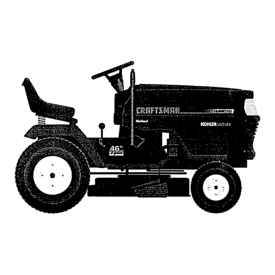
£RRFTSMRN OWNER'S 18.5 HP TWIN CYLINDER MANUAL ELECTRIC START 46" MOWER 6 SPEED TRANSAXLE GARDEN TRACTOR MODEL NO. Each tractor has its own model number. Each engine has its own model nurnber_ 917.258861 The model number for your tractor will be found on the model plate located under the seat.
Need help?
Do you have a question about the EZ3 917.258861 and is the answer not in the manual?
Questions and answers