Table of Contents
Advertisement
Quick Links
®
MODELNUMBER
917.258553
o Assembly
o Operation
o Customer Responsibilities
Service and Adjustments
o Repair Parts
OWNER'S MANUAL
CAUTION:
Read and follow
all safety
rules and instructions
before operating
this equipment.
FOR CONSUMER ASSISTANCE HOT LINE, CALL THIS TOLL FREE NUMBER: 1-800-659-5917
_-
IIIIIIII I
Advertisement
Table of Contents

Related Manuals for Craftsman EZ3 917.258553


Summary of Contents for Craftsman EZ3 917.258553
- Page 1 ® MODELNUMBER 917.258553 OWNER'S MANUAL o Assembly o Operation o Customer Responsibilities Service and Adjustments o Repair Parts CAUTION: Read and follow all safety rules and instructions before operating this equipment. FOR CONSUMER ASSISTANCE HOT LINE, CALL THIS TOLL FREE NUMBER: 1-800-659-5917 IIIIIIII I...
- Page 2 SAFETY RULES Safe Operation Practices for Ride-On Mowers IMPORTANT: THIS CUTT_NG MACHINE IS CAPABLE OF AMPUTATING HANDS AND FEET AND THROWING OBJECTS° FAILURE TO OBSERVE THE FOLLOWING SAFETY INSTRUCTIONS COULD RESULT IN SERIOUS iNJURY OR DEATH tii. CHILDREN GENERAL OPERATION Read, understand, and follow all instructions in the manual Tragic accidents...
- Page 3 LIMITED TWO YEAR WARRANTY ON CRAFTSMAN RIDING EQUIPMENT For two (2) years from the date of purchase, if this Craftsman Riding Equipment is maintained, lubricated and tuned up according to the instructions in the owner's manual, Sears will repair or replace, free of charge, any parts found to be defective in material or workmanship.
- Page 4 TABLE OF CONTENTS SAFETY RULES ............OPERATION ............10-15 PRODUCT SPECIFICATIONS ........MAINTENANCE SCHEDULE ........CUSTOMER RESPONSIBILITIES ..... 3, 16-19 SERVICE AND ADJUSTMENTS ......20-25 WARRANTY ..............STORAGE ..............TABLE OF CONTENTS ..........TROUBLESHOOTING ..........27-28 INDEX ........;......... REPAIR PARTS - TRACTOR ......... 30-47 TRACTOR ACCESSORIES ..........
-
Page 5: Accessories
iii1,1 i i ..... I,,IL,,I i .." ,i i,i ACCESSORIES AND ATTACHMENTS iiiii ......i, ,i IINIIH,II ........These accessories and attachments were available through most Sears retail outletsand service centers when the tractorwas purchased, Most Sears stores can order these items for you when you provide the model number of your tractor. ENGINE MAINTENANCE SPARK PLUG... - Page 6 PACK CONTENTS OF HA i ,u i,,,u,,,,,u , iiiiiil,l,l,,u ii i,u,i Parts packed separately in carton Parts Bag contents shown full size ii ,,11,111..(t) Large Flat Washer (1) Lockwasher Seat Mulcher Plate (!) Hex Bolt 3/8-16 x 1 Vide_ ° Steering Wheel Cassette...
- Page 7 ASSEMBLY Your new tractor has been assembled at the factory with exception of those parts left unassembled for shipping purposes, To ensure safe and proper operation of your tractor all parts and hardware you assemble must be tightened securely° Use the correct tools as necessary to insure proper tightness.
- Page 8 • First connect RED battery cable to positive (+) terminal with hex bolt, flat washer, lock washer and hex nut as SEAT shown. Tighten securely. • Connect BLACK grounding cable to negative (-) termi.. SEAT PAN nal with remaining hex bolt, flat washer, lock washer and hex nut.
- Page 9 1,1,1,,, ,i,,11 , ....ii ii i ..... ASSEMBLY TO CONVERT TO BAGGING GAUGE WHEEL MOUNTING DISCHARGING BRACKET Simply remove mulcher plate and store in a safe place, Your mower is now ready for discharging or installation of optional grass catcher accessory. DEFLECTOR SHIELD 3_-16...
- Page 10 ml,, OPERATION These symbols may appear on your tractor or in literature Supplied with the product. Learn and understand their meaning. BATTERY CAUTION OR FORWARD FAST SI.OW WARNING ENGINE ON ENGINE OFF OIL PRESSURE CLUTCH LIGHTS ON LIGHTS OFF FUEL CHOKE MOWER HEIGHT DIFFERENTIAL...
- Page 11 OPERATION KNOW YOUR TRACTOR READ THIS OWNER'S MANUAL AND SAFETY RULES BEFORE OPERATING YOUR TRACTOR Compare iheillustrationswithyour tractor tofamiliadzeyourself withthe locations of various controls and adjustments. Save this manual for future reference° ATTACHMENT IGNITION LIGHT SWITCH CLUTCH LEVER SWITCH POSITION AMMETER .
- Page 12 OPERATION i1,, ,1 n, ,,,i =1, _,,_,, ..The operation of any tractor can result in foreign objects thrown into the eyes, which can result in severe eye damage. Always wear safety glasses or eye shields while operating your tractor or performing any adjustments or repairs.
-
Page 13: Carburetor
OPERATmON • Raise attachment lift to highest position with attach- TO OPERATE MOWER (See Fig. 10) ment lift control. Your tractor isequipped with an operator presence sensing ° Pull freewheel control knob out and hold in position by switch. Any attempt by the operator to leave the seat with inserting retainer spring into forward hole of control rod. - Page 14 OPERATION PURGE TRANSMISSION TO START ENGINE (See Fig, 9) When starting the engine for the first time or if the engine CAUTION'_"Never engage Or disengag_q has run out of fuel, it will take extra cranking time to move fuel from the tank to the engine, freewheel lever while the engine is run- Be sure freewheel Control is in the transmission...
- Page 16 CUSTO BILmES MAINTENANCE SCHEDULE FILL IN DATES AS YOU COMPLETE REGULAR SERVICE SERVICE DATES CheckBrake Operation Check Tire Pressure Check for Loose @_'7 Fasteners Sharpen/Repiace Mower Blade's ..EUloricaiionchart ....T Chec. k Battery LevettRecharge ....Clean Battery and Terminals ..
- Page 17 .ITI.I i.ii ....i ......CUSTOMER RESPONSiBiLITiES iii1..i.,.., i1.111111.111 TRACTOR TO SHARPEN BLADE (See Fig. 14) Care should be taken to keep the blade balanced. Always observe safety rules when performing any mainte- unbalanced blade will cause excessive vibration and even- r_ance°...
- Page 18 CUSTOMER Inspect cooling fan to be sure fan blades are intact and clean. AIR CLEANER COVER WING NUT Inspect cooling fins for dirt, grass clippings and other materials. To prevent damage to seals, do not use compressed air or high pressure sprayer to clean FOAM cooling fins_ PRE-CLEANER...
- Page 19 ,,,,,,, _,,,L ,,,,,,, ........i1=1==111'1, II="I'N'=I N' , ..CUSTOMER RESPONSIBILITIES MUFFLER CLEAN AIR SCREEN (See Fig. 16) Air screen must be kept free of dirt and chaff to prevent Inspect and replace corroded muffler and spark arrester (if equipped) as it could create a fire hazard and/or damage.
- Page 20 ' i ..i ii ...... i1,,,,,,,i..SERVICE AND ADJUSTMENTS ==.= =11 ..i ii...i,r,,i,rl ...... ,IH, ,_,%Yii,i_, l ill,, CAUTION: BEFORE PERFORMING ANY SERVICE OR ADJUSTMENTS: Place motion control lever in neutral (N) position. Depress clutch/brake pedal fully and set parking brake. Place attachment clutch in "DISENGAGED"...
-
Page 21: Side-To-Side
TO LEVEL MOWER HOUSING FRONT-TO-BACK ADJUSTMENT (See Figs. 22 and 23) Adjust the mower whlle tractor is parked on level ground or IMPORTANT: DECK MUST BE LEVEL SIDE-TO-SIDEo IF THE FOLLOWING FRONT-TO-BACK ADJUSTMENT driveway. Make sure tires are properly inflated (See NECESSARY, BE SURE TO ADJUST BOTH FRONT LINKS "PRODUCT SPECIFICATIONS"... - Page 22 SERVIC AND ADJUSTMENTS TO REPLACE MOWER BLADE DRIVE BELT Depress clutch,_rake pedal and engage parking brake. (See Fig. 24) ° Measure distance between brake operating arm and nut "A" on brake rod. The mower blade drive belt may be replaced without tools. Park the tractor on level surface.
- Page 23 ,,_, , ,, ,,,,L ..,,un !, : ..SERVICE AND ADJUSTMENTS TO ADJUST MOTION CONTROL LEVER TO ADJUST STEERING WHEEL ALIGNMENT (See Fig. 27) If steering wheel crossbars are not horizontal (left to right) when wheels are positioned straight forward, remove steer- The motion control lever has been preset at the factory and ing wheel and reassemble per instructionsin the Assembly adjustment should not be necessary_...
- Page 24 TO START ENGINE WiTH A WEAK BATTERY TO REPLACE HEADLIGHT BULB (See Fig. 29) • Raise hood° Pull bulb holder out of the hole in the backstde of the CAUTION: Lead-acid batteries gener- grill Q ,_- _. ateexplosivegases. Keepsparks, flame °...
-
Page 25: Throttle Control Cable 2
SERVICE AND ADJUSTMENTS ENGINE ACCELERATION TEST- • Move throttle control lever from slow (,I_.) to fast (,,_) TO ADJUST THROTTLE CONTROL CABLE position, If engine dies, hesitates turn idle fuel adjusting needle out (counterclockwise) 1/8 turn. (See Fig. 31) peat test and continue to adjust, if necessary, until... -
Page 26: Cleaning
ENGINE Immediately prepare your tractor for storage at the end of the season or if the tractor will not be used for 30 days or FUEL SYSTEM more° IMPORTANT: iT IS IMPORTANT TO PREVENT GUM DEPOSITS FROM FORMING IN ESSENTIAL FUEL gasoline in the tank inside a building SYSTEM PARTS SUCH AS CARBURETOR, FUEL FILTER,... - Page 27 TROUBLESHOOTING POINTS i.,,' ,i ..,,,,,,,,, ,::: PROBLEM CAUSE CORRECTION iiiiiiii ..IIIr'l"'ll I I'111III Will not start Out offuef Fill fuel tank Engine not "CHOKED" propariy_ See "TO START ENGINE" in Operation section, Engine flooded, Wait severer minutes before attempting to start Bad spark plug Replace spark plug Dirty air filter.
- Page 28 TROUBLESHOOTING POINTS PROBLEM CAUSE CORRECTION Engine continues to run FauIty operator-safety presence control system Check wiring, switches and connections. If not when operator leaves seat corrected, contact an authorized service center/ with attachment clutch department engaged Poorcut-uneven Worn, bent or loose blade, Replace blade Tighten blade bolt, Mower deck not level...
- Page 29 TRACTOR - - MODEL NUMBER 917.258553 SCHEMATIC 0111o SLACK BATTERY FUSE 30 AMP. AMMETER (OPTIONAL) I-(3 WHITE ..iiL_ STARTER sLAcK L ..CLUTCH / BRAKE (PEDAL UP) WHITE o ooo0P, O WHITE SWITCH ___.__ , BLACK _ I _LACK BLACK (CLUTCH OFF) GROUNDING...
- Page 30 REPAIR PARTS TRACTOR -- MODEL NUMBER 917.258553 ELECTRICAL -- ..
- Page 31 REPAIR PARTS TRACTOR - - MODEL NUMBER 917.258553 ELECTRICAL PART DESCRIPTION 146140 Battery 12 Volt 30 Amp 74760412 Bolt, Hex Head 1/4-20 unc x 3/4 STD551025 Washer STD551125 Washer STD541025 109238X Tube, Plastic, 12" 156417 Case, Battery Mech Hinge 't09596X Clamp, Hose 153664 Switch, Tnterlock Push-In...
- Page 32 REPAIR PARTS TRACTOR - - MODEL NUMBER 917.258553 CHASS!S AND ENCLOSURES...
- Page 33 REPAIR PARTS TRACTOR -- MODEL NUMBER 917.258553 CHASSIS AND ENCLOSURES PART DESCRIPTION 159527 Chassis Assembly 140356 Drawbar 17490612 Screw, Thd° Roll. 3/8-16 x 3/4 19131216 Washer 13/32 x 3/4 x 16 Gauge 155272 Bumper Hood/Dash 150156X011 Dash STD533710 Bolt, Carriage 3/8-16 x 3/4. 155927 Panel, Dash, L.H.
- Page 34 REPAIR PARTS TRACTOR - - MODEL NUMBER 917.258553 DRIVE...
- Page 35 REPAIR PARTS TRACTOR - - MODEL NUMBER 917.258553 DRIVE PART PART DESCRIPTION DESCRIPTION 150071 Transaxie Assembly 17490612 Screw Thdrol. 3/8-16 x 3/4 Tyo TT Cover, Pedal 142431 Spring, Return, Brake 8883R Pulley, Engine 143995 Pulley, Transaxle 140186 Bolt Hex 7/t6-20 x 4 Gr. 5 154792 Rod Shift Hydro LT 71t70764...
- Page 36 REPAIR PARTS TRACTOR - - MODEL NUMBER 917.258553 STEERING ASSEMBLY t _- "_63...
- Page 37 REPAIR PARTS TRACTOR - - MODEL NUMBER 917.258553 STEERING ASSEMBLY PART DESCRIPTION 121472X Steering Wheel 154427 Axle Assembly STMP Dropped STL 156483 Spindle Assembly, L.H. 157473 Spindle Assembly, R_H. 6266H Bearing, Race, Thrust, Hardened 121748X Washer 25/32 x 1-5/8 x 16 Gauge 19272016 Washer 27/32 x 1-1/4 x 16 Gauge 12000029...
-
Page 38: Table Of Contents
REPAIR PARTS TRACTOR - - MODEL NUMBER 917.258553 SEAT ASSEMBLY PART PART DESCRIPTION DESCRIPTION 140123 Seat 134300 Spacer, Split _28 x .88 140551 Bracket, Pivot, Seat 121250X Spring STD523710 Bolt 123976X Lecknut, Flange 1/4 Grade 5 '1913t6'10 Washer 13/32 x ! x 10 Gauge 153236 Bolt, Shoulder 5/16-18 UNC... -
Page 39: Key Part No
Decal, Fender Auto Sears Gold 156787 138311 Decal, Deck Mower EZ3 Decal, Lift Handle 146709 154515 Pad Footrest LH STLT Decal, Fender, Craftsman 156439 154516 Pad Footrest RH STLT Decal, Fender Danger 142341 160653 Decal, Drawbar Cntrl Mvt Hyd Lt... -
Page 40: Tractor - - Model Number 917.258553
REPAIR PARTS TRACTOR - - MODEL NUMBER 917.258553 ENGINE OPTIONAL EQUIPMENT Spark Arrester... -
Page 41: Key No
REPAIR PARTS TRACTOR -- MODEL NUMBER 917.258553 ENGINE PART DESCRIPTION 147025 Control, Throttle 17720410 Screw, Hex Head, Thread Cutting 1/4-20 x 5/8 Engine, (See Breakdown) Kohler Model Noo CV15S-41526 Muffler 137350 13280328 Nipple, Pipe 3/8 NPT x 3-1/2 13200300 Elbow, Standard 90 °, 3/8-18 NPT Washer STD551237 Shield, Heat... - Page 42 REPAIR PARTS TRACTOR - - MODEL NUMBER 917.258553 MOWER LIFT...
- Page 43 REPAIR PARTS TRACTOR - - MODEL NUMBER 917.258553 MOWER LIFT PART DESCRIPTION 159460 Lift Lever inner Wire Assembly 159471 Shaft Assembly, Lift 105767X Pin, Groove 12000002 E-Ring 19211621 Washer 21/32 x I x 21 Gauge 120t83X Bearing, Nylon 125631X Grip, Handle, Fluted 122365X Button, Plunger, Red '139865...
- Page 44 REPAIR PARTS TRACTOR -- MODEL NUMBER 917o258553 MOWER DECK 113 111 118 _ 15.-_ "...
-
Page 45: Part No
REPAIR PARTS TRACTOR - - MODEL NUMBER 917.258553 MOWER DECK PART PART DESCRIPTION DESCRIPTION 144393 Mower Housing 140086 Spring, Torsion Brakes STD533107 Bolt 141043 Guard, TUV Idler 138017 Bracket Assembly,Sway Bar, Front 149846 Knob Custom Oval 138440 Bracket Assembly, Sway Bar 144200 V-Belt STD624008... - Page 46 REPAIR PARTS TRACTOR -- MODEL NUMBER 917.258553 HYDRO GEAR TRANSAXLE - MODEL NUMBER 310-0650 "36...
- Page 47 REPAIR PARTS TRACTOR - - MODEL NUMBER 917.258553 HYDRO GEAR TRANSAXLE - MODEL NUMBER 310-0650 KEY PART KEY PART NO. NO. DESCRIPTION NO. NO. DESCRIPTION 142930 Housing, Lower 142884 Washer 7/16 x 7/8 x .060 142931 Assembly, Upper Housing 150829 Differential Assembly '142932 Seal, Lip...
- Page 48 REPAIR PARTS TRACTOR-- MODEL NUMBER 917.258553 KOHLER ENGINE -- MODEL NUMBER CV15S, TYPE NUMBER PS-41526 BLOWER HOUSING AND BAFFLES 13-% __ ........H HI ENGINE CONTROLS CRANKSHAFT H,IH,I I e_16 EXHAUST...
- Page 49 REPAIR PARTS TRACTOR - - MODEL NUMBER 917.258553 KOHLER ENGINE -- MODEL NUMBER CV15S, TYPE NUMBER PS-41526 AIR INTAKE ENGINE CONTROLS KEY PART KEY PART NO, NO. DESCRIPTION NO. NO. DESCRIPTION 12-743-05 Kit, Air Cleaner 12-079-07 Linkage, Choke (Includes Key Numbers 2 thru 12) 12-237-01 Clamp, Cable 25-341-02...
- Page 50 REPAIR PARTS TRACTOR - - MODEL NUMBER 917.258553 KOHLER ENGINE -- MODEL NUMBER CV15S, TYPE NUMBER PS-41526 FUEL SYSTEM llllllllllNl!l ii i,iiii i,ii, i1,111 CYLINDER HEAD, VALVE AND BREATHER...
- Page 51 REPAIR PARTS TRACTOR - - MODEL NUMBER 917.258553 KOHLER ENGINE -- MODEL NUMBER CV15S, TYPE NUMBER PS-41526 FUEL SYSTEM CYLINDER HEAD, VALVE AND BREATHER KEY PART KEY PART NO. NO. DESCRIPTION NO. NO. DESCRIPTION 12-853-56 12-351-01 Kit, Carburetor (Includes #2 thru 6) Lifter, Valve (2) 12-041-02 12-755-60...
- Page 52 REPAIR PARTS TRACTOR - - MODEL NUMBER 917,258553 KOHLER ENGINE -- MODEL NUMBER CV15S, TYPE NUMBER PS-41526 i,ii ,i ..oi,_ PAN .'I;uB_iCATION I ..mN,TtON ,' E LECTRICAL l 0--4 6.++.i_ 8--_ --16 24 + C_--20 _--21 13 __ CRANKCASE STARTING SYSTEM...
- Page 53 REPAIR PARTS TRACTOR -- MODEL NUMBER 917.258553 KOHLER ENGINE -- MODEL NUMBER CV15S, TYPE NUMBER PS-41526 CRANKCASE iGNITION / ELECTRICAL KEY PART KEY PART NO. NO. DESCRIPTION NO. NO. DESCRIPTION Seal, Crankshaft 12-086-14 Screw, Hex Flange 12-032-03 Block, Cylinder (Use Short Block) MI0 x 1.5 x46 12-522-18 Strap, Lifting...
- Page 54 ,i,,,,11 i,,,,,11 ,,,11 ,,i RVICE i1,_1111,1 iiii i'1,...
- Page 55 SUGGESTED GUIDE FOR SaGHTtNG SLOPES FOR SAFE OPERATION ,-,,.., ONLY RIDE UP AND DOWN HILL, NOT ACROSS HILL SIGHTING GUIDE SIGHT AND HOLD THIS LEVEL WITH SKY LINE OR TREE. 15 ° MAX.
-
Page 56: Replacement
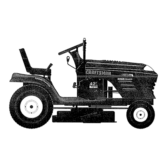
® OWNER'S 15.0 HP MANUAL ELECTRIC START 42" MOWER AUTOMATIC (HYDROSTATIC) LAWN TRACTOR MODEL NO. Each tractor has its own model number. Each engine has its own model number. 917.258553 The model number for your tractor well be found on the model plate located under the seat.
Need help?
Do you have a question about the EZ3 917.258553 and is the answer not in the manual?
Questions and answers