Table of Contents
Advertisement
GA-MA790X-UD4P
AM2+/AM2 socket motherboard for
AMD Phenom
TM
AMD Phenom
TM
AMD Phenom
TM
AMD Athlon
processor/AMD Sempron
TM
AMD Sempron
TM
User's Manual
Rev. 1003
12ME-MA79U4P-1003R
II X3 processor/AMD Phenom
FX processor/AMD Phenom
X3 processor/AMD Athlon
processor
II X4 processor/
TM
X4 processor/
TM
X2 processor/
TM
X2 processor/
TM
Advertisement
Table of Contents
Troubleshooting

Subscribe to Our Youtube Channel
Related Manuals for Gigabyte GA-MA790X-UD4P


Summary of Contents for Gigabyte GA-MA790X-UD4P
- Page 1 GA-MA790X-UD4P AM2+/AM2 socket motherboard for AMD Phenom II X3 processor/AMD Phenom II X4 processor/ AMD Phenom FX processor/AMD Phenom X4 processor/ AMD Phenom X3 processor/AMD Athlon X2 processor/ AMD Athlon processor/AMD Sempron X2 processor/ AMD Sempron processor User's Manual Rev. 1003...
-
Page 3: Identifying Your Motherboard Revision
GIGABYTE's prior written permission. Documentation Classifications In order to assist in the use of this product, GIGABYTE provides the following types of documentations: For quick set-up of the product, read the Quick Installation Guide included with the product. -
Page 4: Table Of Contents
Table of Contents Box Contents ......................... 6 Optional Items ......................... 6 GA-MA790X-UD4P Motherboard Layout ............... 7 Block Diagram ........................ 8 Chapter 1 Hardware Installation ..................9 Installation Precautions ..................9 Product Specifications ..................10 Installing the CPU and CPU Cooler .............. 13 1-3-1 Installing the CPU .................... - Page 5 Configuring SATA Hard Drive(s) ..............75 5-1-1 Configuring AMD SB750 SATA Controllers ............75 5-1-2 Configuring GIGABYTE SATA2 SATA Controller ..........81 5-1-3 Making a SATA RAID/AHCI Driver Diskette for Windows XP ......87 5-1-4 Installing the SATA RAID/AHCI Driver and Operating System ...... 88 Configuring Audio Input and Output ..............
-
Page 6: Box Contents
Box Contents GA-MA790X-UD4P motherboard Motherboard driver disk User's Manual Quick Installation Guide One IDE cable Four SATA 3Gb/s cables One SATA bracket I/O Shield • The box contents above are for reference only and the actual items shall depend on product package you obtain. -
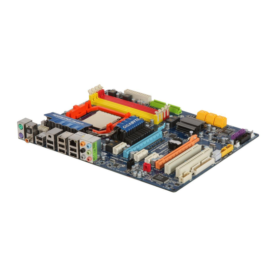
Page 7: Ga-Ma790X-Ud4P Motherboard Layout
GA-MA790X-UD4P Motherboard Layout CPU_FAN KB_MS RCA_SPDIF ATX_12V_2X4 R_USB Socket AM2 USB_1394_1 USB_1394 AUDIO F_AUDIO PCIEX1_1 AMD 790X RTL8111C/D(L) PCIEX16_1 GA-MA790X-UD4P PCIEX1_2 SATA2_4 CD_IN AMD SB750 SATA2_5 SATA2_2 PCIEX1_3 CODEC SATA2_3 BATTERY SATA2_0 CLR_CMOS B_BIOS SPDIF_IN SATA2_1 PCIEX8_1 M_BIOS SPDIF_OUT GIGABYTE... -
Page 8: Block Diagram
PCIe CLK Dual BIOS (100 MHz) 6 SATA 3Gb/s 3 PCI Express x1 ATA-133/100/66/33 IDE Channel RJ45 AMD SB750 RTL8111C/D(L) 12 USB Ports GIGABYTE 2 SATA 3Gb/s SATA2 PCI Bus Floppy LPC BUS COM Port IT8720 TSB43AB23 CODEC PS/2 KB/Mouse... -
Page 9: Chapter 1 Hardware Installation
Chapter 1 Hardware Installation Installation Precautions The motherboard contains numerous delicate electronic circuits and components which can become damaged as a result of electrostatic discharge (ESD). Prior to installation, carefully read the user's manual and follow these procedures: Prior to installation, do not remove or break motherboard S/N (Serial Number) sticker or •... -
Page 10: Product Specifications
X3 processor/AMD Athlon X2 processor/ AMD Athlon processor/AMD Sempron X2 processor/ AMD Sempron processor (Go to GIGABYTE's website for the latest CPU support list.) Hyper Transport Bus 5200/2000 MT/s Chipset North Bridge: AMD 790X South Bridge: AMD SB750 ... - Page 11 Internal Connectors 1 x 24-pin ATX main power connector 1 x 8-pin ATX 12V power connector 1 x floppy disk drive connector 1 x IDE connector 8 x SATA 3Gb/s connectors 1 x CPU fan header ...
- Page 12 (Note 5) Available functions in EasyTune may differ by motherboard model. (Note 6) Due to the hardware limitation, you must install the AMD AM3 Phenom II/AM2+ Phenom Series CPU toenable support for Easy Energy Saver. GA-MA790X-UD4P Motherboard - 12 -...
-
Page 13: Installing The Cpu And Cpu Cooler
Read the following guidelines before you begin to install the CPU: • Make sure that the motherboard supports the CPU. (Go to GIGABYTE's website for the latest CPU support list.) • Always turn off the computer and unplug the power cord from the power outlet before installing the CPU to prevent hardware damage. - Page 14 CPU, lowering the locking lever and latch- ing it into the fully locked position. Do not force the CPU into the CPU socket. The CPU cannot fit in if oriented incorrectly. Adjust the CPU orientation if this occurs. GA-MA790X-UD4P Motherboard - 14 -...
-
Page 15: Installing The Cpu Cooler
1-3-2 Installing the CPU Cooler Follow the steps below to correctly install the CPU cooler on the CPU. (The following procedure uses the GIGABYTE cooler as the example.) Step 1: Step 2: Apply an even and thin layer of thermal grease Place the CPU cooler on the CPU. -
Page 16: Installing The Memory
• Make sure that the motherboard supports the memory. It is recommended that memory of the same capacity, brand, speed, and chips be used. (Go to GIGABYTE's website for the latest memory support list.) • Always turn off the computer and unplug the power cord from the power outlet before installing the memory to prevent hardware damage. -
Page 17: Installing A Memory
1-4-2 Installing a Memory Before installing a memory module , make sure to turn off the computer and unplug the power cord from the power outlet to prevent damage to the memory module. DDR2 DIMMs are not compatible to DDR DIMMs. Be sure to install DDR2 DIMMs on this motherboard. -
Page 18: Installing An Expansion Card
PCI Ex- and then lift the card press slot to release the straight out from the slot. card and then pull the card straight up from the slot. GA-MA790X-UD4P Motherboard - 18 -... -
Page 19: Configuring An Ati Crossfirex
Configuring an ATI CrossFireX System To enable CrossFireX technology, you need two graphics cards that support ATI CrossFire technology. Before You Begin-- A. Power Requirements: Use a power supply that is able to provide sufficient power to fully support an CrossFireX configuration and other components in your system. -
Page 20: Installing The Sata Bracket
SATA device. For SATA device in external enclosure, you only need to connect the SATA signal cable. Before connecting the SATA signal cable, make sure to turn off the power of the external enclosure. GA-MA790X-UD4P Motherboard - 20 -... -
Page 21: Back Panel Connectors
Back Panel Connectors PS/2 Keyboard and PS/2 Mouse Port Use the upper port (green) to connect a PS/2 mouse and the lower port (purple) to connect a PS/2 keyboard. Coaxial S/PDIF Out Connector This connector provides digital audio out to an external audio system that supports digital coaxial audio. - Page 22 Only microphones still MUST be connected to the default Mic in jack ( ). Refer to the instructions on setting up a 2/4/5.1/ 7.1-channel audio configuration in Chapter 5, "Configuring 2/4/5.1/7.1-Channel Audio." GA-MA790X-UD4P Motherboard - 22 -...
-
Page 23: Internal Connectors
Internal Connectors ATX_12V_2X4 F_AUDIO CD_IN CPU_FAN SPDIF_IN SYS_FAN1/SYS_FAN2 SPDIF_OUT PWR_FAN F_USB1 / F_USB2 F_1394 SATA2_0 / 1 / 2 / 3 / 4 / 5 GSATA2_0/GSATA_1 CLR_CMOS PWR_LED BATTERY F_PANEL Read the following guidelines before connecting external devices: • First make sure your devices are compliant with the connectors you wish to connect. •... - Page 24 Pin No. Definition 3.3V 3.3V 3.3V -12V PS_ON(soft On/Off) Power Good 5V SB(stand by +5V) +12V +12V (Only for 2x12-pin ATX) +5V (Only for 2x12-pin ATX) 3.3V (Only for 2x12-pin ATX) GND (Only for 2x12-pin ATX) GA-MA790X-UD4P Motherboard - 24 -...
- Page 25 3/4/5) CPU_FAN / SYS_FAN1 / SYS_FAN2 / PWR_FAN (Fan Headers) The motherboard has a 4-pin CPU fan header (CPU_FAN), a 4-pin (SYS_FAN1) and two 3-pin (SYS_FAN2) system fan headers, and a 3-pin power fan header (PWR_FAN). Most fan headers possess a foolproof insertion design. When connecting a fan cable, be sure to connect it in the correct orientation (the black connector wire is the ground wire).
- Page 26 • A RAID 5 configuration requires at least three hard drives. (The total number of hard drives does not have to be an even number.) • A RAID 10 configuration requires at least four hard drives and the total number of hard drives must be an even number. GA-MA790X-UD4P Motherboard - 26 -...
- Page 27 The SATA connectors conform to SATA 3Gb/s standard and are compatible with SATA 1.5Gb/s standard. Each SATA connector supports a single SATA device. The GIGABYTE SATA2 controller supports RAID 0 and RAID 1. Refer to Chapter 5, "Configuring SATA Hard Drive(s)," for instructions on configuring a RAID array.
-
Page 28: F_Panel Front Panel Header
LED, hard drive activity LED, speaker and etc. When connecting your chassis front panel module to this header, make sure the wire assign- ments and the pin assignments are matched correctly. GA-MA790X-UD4P Motherboard - 28 -... -
Page 29: Cd In Connector
12) F_AUDIO (Front Panel Audio Header) The front panel audio header supports Intel High Definition audio (HD) and AC'97 audio. You may connect your chassis front panel audio module to this header. Make sure the wire assignments of the module connector match the pin assignments of the motherboard header. Incorrect connection between the module connector and the motherboard header will make the device unable to work or even damage it. -
Page 30: S/Pdif Out Header
HDMI display to the graphics card and have digital audio output from the HDMI display at the same time. For information about connecting the S/PDIF digital audio cable, carefully read the manual for your expansion card. Pin No. Definition SPDIFO GA-MA790X-UD4P Motherboard - 30 -... -
Page 31: F_1394 Ieee 1394A Header
16) F_USB1/F_USB2 (USB Headers) The headers conform to USB 2.0/1.1 specification. Each USB header can provide two USB ports via an optional USB bracket. For purchasing the optional USB bracket, please contact the local dealer. Pin No. Definition Power (5V) Power (5V) USB DX- USB DY-... - Page 32 19) CI (Chassis Intrusion Header) This motherboard provides a chassis detection feature that detects if the chassis cover has been removed. This function requires a chassis with chassis intrusion detection design. Pin No. Definition Signal GA-MA790X-UD4P Motherboard - 32 -...
-
Page 33: Battery
20) CLR_CMOS (Clearing CMOS Jumper) Use this jumper to clear the CMOS values (e.g. date information and BIOS configurations) and reset the CMOS values to factory defaults. To clear the CMOS values, place a jumper cap on the two pins to temporarily short the two pins or use a metal object like a screwdriver to touch the two pins for a few seconds. - Page 34 GA-MA790X-UD4P Motherboard - 34 -...
-
Page 35: Chapter 2 Bios Setup
To see more advanced BIOS Setup menu options, you can press <Ctrl> + <F1> in the main menu of the BIOS Setup program. To upgrade the BIOS, use either the GIGABYTE Q-Flash or @BIOS utility . Q-Flash allows the user to quickly and easily upgrade or back up BIOS without entering the •... -
Page 36: Startup Screen
A. The LOGO Screen (Default) Function Keys B. The POST Screen Award Modular BIOS v6.00PG, An Energy Star Ally Copyright (C) 1984-2009, Award Software, Inc. GA-MA790X-UD4P E3 Motherboard Model BIOS Version Function Keys <DEL>: BIOS Setup <F9>: XpressRecovery2 <F12>: Boot Menu <End>: Qflash... -
Page 37: The Main Menu
The Main Menu Once you enter the BIOS Setup program, the Main Menu (as shown below) appears on the screen. Use arrow keys to move among the items and press <Enter> to accept or enter a sub-menu. (Sample BIOS Version: E3) CMOS Setup Utility-Copyright (C) 1984-2009 Award Software ... - Page 38 Exit Without Saving Abandon all changes and the previous settings remain in effect. Pressing <Y> to the confirmation message will exit BIOS Setup. (Pressing <Esc> can also carry out this task.) GA-MA790X-UD4P Motherboard - 3 8 -...
-
Page 39: Mb Intelligent Tweaker(M.i.t.)
MB Intelligent Tweaker(M.I.T.) CMOS Setup Utility-Copyright (C) 1984-2009 Award Software MB Intelligent Tweaker(M.I.T.) CPU Clock Ratio [Auto] 2600Mhz Item Help (Note) CPU NorthBridge Freq. [Auto] 2600Mhz Menu Level CPU Host Clock Control [Auto] x CPU Frequency (MHz) PCIE Clock (MHz) [Auto] HT Link Frequency [Auto]... - Page 40 When you use a AM3 CPU: X2.00 Sets Memory Clock to X2.00. X2.66 Sets Memory Clock to X2.66. X3.33 Sets Memory Clock to X3.33. X4.00 Sets Memory Clock to X4.00. X5.33 Sets Memory Clock to X5.33. GA-MA790X-UD4P Motherboard - 4 0 -...
-
Page 41: Dram Configuration
DRAM Configuration CMOS Setup Utility-Copyright (C) 1984-2009 Award Software DRAM Configuration Item Help CPU Host Clock Control [Auto] x CPU Frequency (MHz) Menu Level Set Memory Clock [Auto] x Memory Clock x2.66 533Mhz (Note) DCTs Mode [Unganged] DDRII Timing Items [Auto] Auto x CAS# latency... - Page 42 Manual allows all voltage control items below to be configurable. (Default: Auto) DDR2 Voltage Control Allows you to set memory voltage. Normal Supplies the memory voltage as required. (Default) +0.100V ~ +0.600V Increases memory voltage by 0.100V to 0.600V at 0.100V increment. GA-MA790X-UD4P Motherboard - 4 2 -...
- Page 43 NorthBridge Volt Control Allows you to set the North Bridge voltage. Normal Supplies the North Bridge voltage as required. (Default) +0.1V ~ +0.3V Increases North Bridge voltage by 0.1V to 0.3V at 0.1V increment. SouthBridge Volt Control Allows you to set the South Bridge voltage. Normal Supplies the South Bridge voltage as required.
-
Page 44: Standard Cmos Features
If no IDE/SATA devices are used, set this item to None so the system will skip the detection of the device during the POST for faster system startup. Access Mode Sets the hard drive access mode. Options are: Auto (default), Large. GA-MA790X-UD4P Motherboard - 4 4 -... - Page 45 The following fields display your hard drive specifications. If you wish to enter the parameters manually, refer to the information on the hard drive. Capacity Approximate capacity of the currently installed hard drive. Cylinder Number of cylinders. Head Number of heads. Precomp Write precompensation cylinder.
-
Page 46: Advanced Bios Features
Password item in the BIOS Main Menu. Setup A password is only required for entering the BIOS Setup program. (Default) System A password is required for booting the system and for entering the BIOS Setup program. GA-MA790X-UD4P Motherboard - 4 6 -... - Page 47 (Default: Disabled) Full Screen LOGO Show Allows you to determine whether to display the GIGABYTE Logo at system startup. Disabled displays normal POST message. (Default: Enabled) Init Display First Specifies the first initiation of the monitor display from the installed PCI graphics card or PCI Express graphics card.
-
Page 48: Integrated Peripherals
Onboard Audio Function Enables or disables the onboard audio function. (Default: Auto) If you wish to install a 3rd party add-in audio card instead of using the onboard audio, set this item to Disabled. GA-MA790X-UD4P Motherboard - 4 8 -... - Page 49 Onboard GSATA-II Ctrl Mode (GIGABYTE SATA2 Chip, GSATA2_0/GSATA2_1 connectors) Enables or disables RAID for the SA TA controller integrated in the GIGABYTE SA TA 2 chip or configures the SATA controller to AHCI mode. Disables RAID for the SATA controller and configures the SATA controller to PATA mode.
- Page 50 POST. (Default: Enabled) Onboard Serial Port 1 Enables or disables the first serial port and specifies its base I/O address and corresponding interrupt. Options are: Auto, 2F8/IRQ3, 3F8/IRQ4(default), 3E8/IRQ4, 2E8/IRQ3, Disabled. GA-MA790X-UD4P Motherboard - 5 0 -...
-
Page 51: Power Management Setup
Power Management Setup CMOS Setup Utility-Copyright (C) 1984-2009 Award Software Power Management Setup ACPI Suspend Type [S3(STR)] Item Help Soft-Off by Power button [Instant-off] Menu Level USB Wake Up from S3 [Enabled] Modem Ring Resume [Disabled] PME Event Wake Up [Enabled] (Note) HPET Support... - Page 52 Note: When using this function, avoid inadequate shutdown from the operating system or removal of the AC power, or the settings may not be effective. (Note) Supported on Windows Vista operating system only. ® ® GA-MA790X-UD4P Motherboard - 5 2 -...
-
Page 53: Pc Health Status
PC Health Status CMOS Setup Utility-Copyright (C) 1984-2009 Award Software PC Health Status Reset Case Open Status [Disabled] Item Help Case Opened Menu Level Vcore 1.376V DDR2 1.8V 1.872V +3.3V 3.328V +12V 12.112V Current System Temperature Current CPU Temperature Current CPU FAN Speed 3375 RPM Current SYSTEM FAN1 Speed Current SYSTEM FAN2 Speed... - Page 54 Enables or disables the system fan speed control function. Enabled allows the system fan to run at different speed according to the system temperature. You can adjust the fan speed with EasyTune based on system requirements. If disabled, system fan runs at full speed. (Default: Enabled) GA-MA790X-UD4P Motherboard - 5 4 -...
-
Page 55: Load Fail-Safe Defaults
Load Fail-Safe Defaults CMOS Setup Utility-Copyright (C) 1984-2009 Award Software MB Intelligent Tweaker(M.I.T.) Load Fail-Safe Defaults Standard CMOS Features Load Optimized Defaults Advanced BIOS Features Set Supervisor Password Integrated Peripherals Set User Password Load Fail-Safe Defaults (Y/N)? N ... -
Page 56: Set Supervisor/User Password
BIOS settings but not to make changes. To clear the password, press <Enter> on the password item and when requested for the password, press <Enter> again. The message "PASSWORD DISABLED" will appear, indicating the password has been cancelled. GA-MA790X-UD4P Motherboard - 5 6 -... -
Page 57: Save & Exit Setup
2-12 Save & Exit Setup CMOS Setup Utility-Copyright (C) 1984-2009 Award Software MB Intelligent Tweaker(M.I.T.) Load Fail-Safe Defaults Standard CMOS Features Load Optimized Defaults Advanced BIOS Features Set Supervisor Password Save to CMOS and EXIT (Y/N)? Y ... - Page 58 GA-MA790X-UD4P Motherboard - 5 8 -...
-
Page 59: Chapter 3 Drivers Installation
Chapter 3 Drivers Installation • Before installing the drivers, first install the operating system. • After installing the operating system, insert the motherboard driver disk into your optical drive. The driver Autorun screen is automatically displayed which looks like that shown in the screen shot below. -
Page 60: Application Software
Application Software This page displays all the utilities and applications that GIGABYTE develops and some free software. You can click the Install button on the right of an item to install it. Technical Manuals This page provides GIGABYTE's application guides, content descriptions for this driver disk, and the motherboard manuals. -
Page 61: Contact
Contact For the detailed contact information of the GIGABYTE Taiwan headquarter or worldwide branch of fices, click the URL on this page to link to the GIGABYTE Website. System This page provides the basic system information. - 61 - Drivers Installation... -
Page 62: Download Center
Download Center To update the BIOS, drivers, or applications, click the Download Center button to link to the GIGABYTE Web site. The latest version of the BIOS, drivers, or applications will be displayed. GA-MA790X-UD4P Motherboard - 6 2 -... -
Page 63: Chapter 4 Unique Features
Chapter 4 Unique Features Xpress Recovery2 Xpress Recovery2 is a utility that allows you to quickly compress and back up your system data and perform restoration of it. Supporting NTFS, FAT32, and FAT16 file systems, Xpress Recovery2 can back up data on PATA and SATA hard drives and restore it. Before You Begin: •... - Page 64 Xpress Recovery2 will automatically create a new partition to store the backup image file. Step 1: Step 2: Select BACKUP to start backing up your hard When finished, go to Disk Management to drive data. check disk allocation. GA-MA790X-UD4P Motherboard - 6 4 -...
- Page 65 D. Using the Restore Function in Xpress Recovery2 Select RESTORE to restore the backup to your hard drive in case the system breaks down. The RESTORE option will not be present if no backup is created before. E. Removing the Backup Step 1: Step 2: If you wish to remove the backup file, select...
-
Page 66: Bios Update Utilities
4-2-1 Updating the BIOS with the Q-Flash Utility A. Before You Begin: 1. From GIGABYTE's website, download the latest compressed BIOS update file that matches your motherboard model. 2. Extract the file and save the new BIOS file (e.g. M79XUD4P.F1) to your floppy disk, USB flash drive, or hard drive. - Page 67 B. Updating the BIOS When updating the BIOS, choose the location where the BIOS file is saved. The follow procedure assumes that you save the BIOS file to a floppy disk. Step 1: 1. Insert the floppy disk containing the BIOS file into the floppy disk drive. In the main menu of Q-Flash, use the up or down arrow key to select Update BIOS from Drive and press <Enter>.
- Page 68 Press <Y> to load BIOS defaults Step 6: Select Save & Exit Setup and then press <Y> to save settings to CMOS and exit BIOS Setup. The procedure is complete after the system restarts. GA-MA790X-UD4P Motherboard - 6 8 -...
-
Page 69: Updating The Bios With The @Bios Utility
BIOS or a system that is unable to start. 3. Do not use the G.O.M. (GIGABYTE Online Management) function when using @BIOS. 4. GIGABYTE product warranty does not cover any BIOS damage or system failure resulting from an inadequate BIOS flashing. -
Page 70: Easytune 6
EasyTune 6 GIGABYTE's EasyTune 6 is a simple and easy-to-use interface that allows users to fine-tune their system settings or do overclock/overvoltage in Windows environment. The user-friendly EasyTune 6 interface also includes tabbed pages for CPU and memory information, lettings users read their system- related information without the need to install additional software. -
Page 71: Easy Energy Saver
The Easy Energy Saver Interface A. Meter Mode In Meter Mode, GIGABYTE Easy Energy Saver shows how much power they have saved in a set period of time. Meter Mode - Button Information Table Button Description... - Page 72 Energy Saver is under the enable status, and power savings meter is unable to reset to zero. (Note 5) Easy Energy Saver Meter will automatically reset when the total power saving reaches 99999999 Watts. GA-MA790X-UD4P Motherboard - 7 2 -...
-
Page 73: Q-Share
Q-Share, you are able to share your data with computers on the same network, making full use of Internet resources. Directions for using Q-Share After installing Q-Share from the motherboard driver disk, go to Start>All Programs>GIGABYTE> Q-Share.exe to launch the Q-Share tool. Find the Q-Share icon in your system tray and right-click on this icon to configure the data sharing settings. -
Page 74: Time Repair
• Each storage volume can accommodate 64 shadow copies. When this limit is reached, the oldest shadow copy will be deleted and unable to be restored. Shadow copies are read-only so you cannot edit the contents of a shadow copy. GA-MA790X-UD4P Motherboard - 7 4 -... -
Page 75: Chapter 5 Appendix
Chapter 5 Appendix Configuring SATA Hard Drive(s) To configure SATA hard drive(s), follow the steps below: A. Install SATA hard drive(s) in your computer . B. Configure SATA controller mode in BIOS Setup. C . Configure a RAID array in RAID BIOS. (Note 1) D. - Page 76 The BIOS Setup menus described in this section may differ from the exact settings for your motherboard. The actual BIOS Setup menu options you will see shall depend on the motherboard you have and the BIOS version. GA-MA790X-UD4P Motherboard - 76 -...
- Page 77 C. Configuring RAID set in RAID BIOS Enter the RAID BIOS setup utility to configure a RAID array. Skip this step if you do not want to create RAID. Step 1: After the POST memory test begins and before the operating system boot begins, look for a message which says "Press <Ctrl-F>...
-
Page 78: Create Arrays Manually
Drive Model Capabilities Capacity (GB) Assignment 1:Mas WDC WD800JD-22LSA0 SATA 3G 79.89 2:Mas WDC WD800JD-22LSA0 SATA 3G 80.02 Keys Available [] Up [] Down [ESC] Exit [Space] Change [Ctrl-Y] Save [PgUp/Dn] Page Change Figure 5 GA-MA790X-UD4P Motherboard - 78 -... -
Page 79: View Drive Assignments
In the following procedure, we'll create RAID 0 as an example. 1. Under the RAID Mode section, press the <SP ACE> key to select RAID 0. 2. Set the Stripe Block size. 64 KB is the default. 3. Under the Drives Assignments section, press the up or down arrow key to highlight a drive. 4. - Page 80 Drive Model Capabilities Capacity (GB) 1:Mas WDC WD800JD-22LSA0 SATA 3G 79.89 2:Mas WDC WD800JD-22LSA0 SATA 3G 80.02 Press Ctrl-Y to delete the data in the disk! or press any other key to abort... Figure 9 GA-MA790X-UD4P Motherboard - 80 -...
-
Page 81: Configuring Gigabyte Sata2 Sata Controller
Attach one end of the SATA signal cable to the rear of the SATA hard drive and the other end to available SATA port on the motherboard. On this motherboard, the GSATA2_0 and GSATA2_1 ports are supported by the GIGABYTE SATA2 SATA controller.) Then connect the power connector from your power supply to the hard drive. - Page 82 Figure 2 In the main screen of the GIGABYTE SATA2 RAID BIOS utility (Figure 3), use the up or down arrow key to highlight through choices in the Main Menu block. Highlight the item that you wish to execute and press <Enter>.
-
Page 83: Create A Raid Array
In the main screen, press <Enter> on the Create RAID Disk Drive item. Then the Create New RAID screen appears (Figure 4). GIGABYTE Technology Corp. PCIE-to-SATAII/IDE RAID Controller BIOS v1.06.59 [ Create New RAID ] [ Hard Disk Drive List ]... - Page 84 4. Set Block Size (RAID 0 only): Under the Block item, use the up or down arrow key to select the stripe block size (Figure 6), ranging from 4 KB to 128 KB. Press <Enter>. GIGABYTE Technology Corp. PCIE-to-SATAII/IDE RAID Controller BIOS v1.06.59 [ Create New RAID ]...
- Page 85 When finished, the new RAID array will be displayed in the RAID Disk Drive List block (Figure 8). GIGABYTE Technology Corp. PCIE-to-SATAII/IDE RAID Controller BIOS v1.06.59 [ Main Menu ] [ Hard Disk Drive List ] Create RAID Disk Drive...
- Page 86 7. Save and Exit Setup: After configuring the RAID array, select the Save And Exit Setup item in the main screen to save your settings before exiting the RAID BIOS utility, then press <Y> (Figure 10). GIGABYTE Technology Corp. PCIE-to-SATAII/IDE RAID Controller BIOS v1.06.78 [ Main Menu ]...
-
Page 87: Making A Sata Raid/Ahci Driver Diskette For Windows Xp
Figure 2: • For AMD SB750 SATA controllers, select 5) SB700/750 SATA for operating system . • For GIGABYTE SATA2 SATA controller, select 1) GIGABYTE SATA-Driver(x86) for Windows 32-bit operating system or 2) GIGABYTE SATA-Driver(x64) for W indows 64-bit operating system. -
Page 88: Installing The Sata Raid/Ahci Driver And Operating System
Select the SCSI Adapter you want from the following list, or press ESC to return to the previous screen. AMD AHCI Compatible RAID Controller-x86 platform AMD AHCI Compatible RAID Controller-x64 platform ENTER=Select F3=Exit Figure 2 GA-MA790X-UD4P Motherboard - 88 -... - Page 89 For GIGABYTE SATA2 SATA controller: Insert the floppy disk containing the SA TA RAID/AHCI driver and press <S>. Then a controller menu similar to Figure 3 below will appear. Select (Windows XP/2003) RAID/AHCI Driver for GIGABYTE GBB36X Controller and press <Enter>.
- Page 90 For Windows Vista 64-bit, browse to the LH64A folder. Method B: Insert the USB flash drive containing the driver files and browse to the LH (for Windows Vista 32-bit) or LH64A (for Windows Vista 64-bit) folder. Figure 5 GA-MA790X-UD4P Motherboard - 90 -...
- Page 91 Step 3: When a screen as shown in Figure 6 appears, select AMD AHCI Compatible RAID Controller and press Next. Figure 6 Step 4: After the driver is loaded, the RAID drive will appear. Select the RAID drive and then press Next to continue the OS installation (Figure 7).
- Page 92 GIGABYTE SATA2 SATA controller: Step 1: Restart your system to boot from the Windows Vista setup disk and perform standard OS installation steps. When a screen similar to that below appears (RAID/AHCI hard drive(s) will not be detected at this stage), select Load Driver (Figure 8).
- Page 93 Step 3: When a screen as shown in Figure 10 appears, select GIGABYTE GBB36X Controller and press Next. Figure 10 Step 4: After the driver is loaded, select the RAID/AHCI drive(s) where you want to install the operating system and then press Next to continue the OS installation (Figure 1 1).
- Page 94 Pause/Resume/ Abort/Restart during the rebuilding process. Step 5: When done, the array's status on the Information page in the Logical Drive Information pane will display as Functional. GA-MA790X-UD4P Motherboard - 94 -...
- Page 95 • GIGAGYTE SATA2 SATA controller: Turn off your computer and replace the failed hard drive with a new one. Use either the GIGABYTE SATA2 RAID BIOS utility or the GIGABYTE RAID CONFIGURER utility in the operating system to perform the rebuild.
- Page 96 Rebuilding in the operating system Make sure the GIGABYTE SATA2 SATA controller driver has been installed from the motherboard driver disk. Launch the GIGABYTE RAID CONFIGURER from All Programs in the Start menu. Step 2: When the Rebuilding RAID Wizard appears, click Step 1: Next.
-
Page 97: Configuring Audio Input And Output
Configuring Audio Input and Output 5-2-1 Configuring 2/4/5.1/7.1-Channel Audio The motherboard provides six audio jacks on the back panel which support 2/4/5.1/7.1-channel audio. Center/Subwoofer The picture to the right shows the default audio Line In Speaker Out jack assignments. The integrated HD (High Definition) Front Speaker Out Rear Speaker Out audio provides jack retasking capability that... - Page 98 Click Device advanced settings on the top right cor- ner on the Speaker Configuration tab to open the Device advanced settings dialog box. Select the Mute the rear output device, when a front headphone plugged in check box. Click OK to complete. GA-MA790X-UD4P Motherboard - 98 -...
-
Page 99: Configuring S/Pdif In/Out
5-2-2 Configuring S/PDIF In/Out A. S/PDIF In: The S/PDIF in cable (optional) allows you to input digital audio signals to the computer for audio processing. S/PDIF In Cable Coaxial Optical S/PDIF In S/PDIF In 1. Installing the S/PDIF In Cable: Step 1: Step 2: First, attach the connector at the end of the cable... - Page 100 Connect a S/PDIF coaxial cable or a S/PDIF optical cable (either one) to an external decoder for transmitting the S/PDIF digital audio signals. 2. Configuring S/PDIF Out: On the Digital Output screen, click the Default Format tab and then select the sample rate and bit depth. Click OK to complete. GA-MA790X-UD4P Motherboard - 100 -...
-
Page 101: Enabling The Dolby Home Theater Function
5-2-3 Enabling the Dolby Home Theater Function Before Dolby Home Theater is enabled, you get only 2-channel playback output (from the front speakers) when playing 2-channel stereo sources. Y ou must play 4-, 5.1-, or 7.1- channel content to get 4-, 5.1-, or 7.1- channel audio effects. With Dolby Home Theater enabled, 2-channel stereo content will be transformed into multi-channel audio, creating a virtual surround sound environment (Note) -
Page 102: Configuring Microphone Recording
It is recommended that you set the volumes at a middle level. If you want to change the current sound input default device to microphone, right-click on Microphone and select Set Default Device. GA-MA790X-UD4P Motherboard - 102 -... - Page 103 Step 4: To raise the recording and playback volume for the microphone, click the Microphone Boost icon on the right of the Recording Volume slider and set the Microphone Boost level. Step 5: After completing the settings above, click Start, point to All Programs, point to Accessories, and then click Sound Recorder to begin the sound recording.
-
Page 104: Using The Sound Recorder
3. To stop recording audio, click the Stop Recording button Be sure to save the recorded audio file upon completion. B. Playing the Recorded Sound: You can play your recording in a digital media player program that supports your audio file format. GA-MA790X-UD4P Motherboard - 104 -... -
Page 105: Troubleshooting
5-3-1 Frequently Asked Questions To read more F AQs for your motherboard, please go to the Support\Motherboard\F AQ page on GIGABYTE's website. Q: In the BIOS Setup program, why are some BIOS options missing? A: Some advanced options are hidden in the BIOS Setup program. Press <Delete> to enter BIOS Setup during the POST. -
Page 106: Troubleshooting Procedure
Turn on the power to start the computer. Press <Delete> to enter BIOS Setup. Select "Load Fail-Safe Defaults" (or "Load Optimized Defaults"). Select "Save & Exit Setup" to save changes and exit BIOS Setup. (Continued...) GA-MA790X-UD4P Motherboard - 106 -... - Page 107 The power supply, When the computer is turned on, is the CPU cooler running? CPU or CPU socket might fail. The problem is verified and solved. The graphics card, Check if there is display on your monitor. expansion slot, or monitor might fail.
-
Page 108: Regulatory Statements
"end of life" product. Restriction of Hazardous Substances (RoHS) Directive Statement GIGABYTE products have not intended to add and safe from hazardous substances (Cd, Pb, Hg, Cr+6, PBDE and PBB). The parts and components have been carefully selected to meet RoHS requirement. - Page 109 Finally, we suggest that you practice other environmentally friendly actions by understanding and using the energy-saving features of this product (where applicable), recycling the inner and outer packaging (including shipping containers) this product was delivered in, and by disposing of or recycling used batteries properly.
- Page 110 GA-MA790X-UD4P Motherboard - 110 -...
- Page 111 TEL: +86-24-83992901 FAX: +86-24-83992909 GIGA-BYTE SINGAPORE PTE. LTD. - Singapore WEB address : http://www.gigabyte.sg GIGABYTE TECHNOLOGY (INDIA) LIMITED - India WEB address : http://www.gigabyte.in Thailand ...
- Page 112 WEB address : http://www.giga-byte.kz Czech Republic You may go to the GIGABYTE website, select your language WEB address : http://www.gigabyte.cz in the language list on the top right corner of the website. GIGABYTE Global Service System...
Need help?
Do you have a question about the GA-MA790X-UD4P and is the answer not in the manual?
Questions and answers