Advertisement
Quick Links
HEATING & COOUNG
Visit www.carrier.cmn
Heat
38EYG
12 SEER Split-System
Pump with Puron® Refrigerant
Installation and Start-Up Instructions
NOTE:
Read
the
entire
instruction
manual
before
starting
the
installation.
This symbol
_
indicates
a change
since the last issue.
SAFETY
CONSIDERATIONS
Improper
installation,
adjustment,
alteration,
service,
maintenance,
or use
can
cause
explosion,
fire,
electrical
shock,
or
other
conditions
which
may
cause
death,
personal
injury,
or property
damage.
Consult
a qualified
installer,
service
agency,
or your
distributor
or branch
for information
or assistance.
The qualified
installer
or agency
must use fiactory-authorized
kits or accessories
when
modifying
this product.
Refer
to the individual
instructions
packaged
with
the kits or accessories
when
installing.
Follow
all safety
codes. Wear
safety
glasses,
protective
clothing,
and work
gloves.
Use
quenching
cloth
for brazing
operations.
Have
fire extinguisher
available.
Read
these
instructions
thor-
oughly
and follow
all warnings
or cautions
included
in literature
and attached
to the unit. Consult
local building
codes and National
Electrical
Code (NEC)
for special
requirements.
Recognize
safety information.
This is the safety-alert
symbol
Z_ •
When
you
see this symbol
on the unit
and
in instructions
or
manuals,
be alert to the potential
for personal
injury.
Understand
the signal words
DANGER,
WARNING,
and CAU-
TION.
These words
are used with the safety-alert
symbol.
DAN-
GER identifies
the most serious hazards
which will result in severe
personal
injury
or death.
WARNING
signifies
hazards
which
could
result
in personal
injury
or death.
CAUTION
is used
to
identify
unsafe
practices
which
would
result
in minor
personal
injury or product
and property
damage.
NOTE
is used to highlight
suggestions
which
will result in enhanced
installation,
reliablitily,
or operation.
¥!_ tVl:1 :]_l_[d
Before
installing,
modifying,
or servicing
system,
main elec-
trical disconnect
switch
must
be in the OFF position.
There
may
be more
than
1 disconnect
switch.
Lock
out and tag
switch
with
a suitable
warning
label.
Electrical
shock
can
cause personal
injury
or death.
r;_[Rr21lii_] iq
Puron_;
(R-410A)
systems
operate
at higher
pressures
than
standard
R-22
systems.
Be certain
that service
eqnipment
is
rated for Puron:,P¢. Some R-22 service
equipment
may not be
acceptable.
Check
with your distributor.
INSTALLATION
RECOMMENDATIONS
NOTE:
In some cases noise in the living area has been traced
to
gas pulsations
from
improper
installation
of equipment.
i. Locate
unit away from windows,
patios,
decks, etc. where unit
operation
sound
may disturb
customer.
2. Ensure
that vapor and liquid tube diameters
are appropriate
to
capacity
of unit.
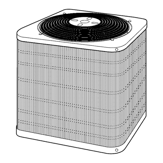
A98525
Fig. 1--Model
38EYG
3. Run refrigerant
tubes
as directly
as possible
by avoiding
unnecessary
tunas and bends.
4. Leave
some
slack
between
structure
and
unit
to
absorb
vibration.
5. When passing
refrigerant
tubes through
the wall, seal opening
with RTV or other pliable
silicon-based
caulk.
(See Fig. 2.)
6. Avoid
direct tubing
contact
with water
pipes, duct work, floor
joists,
wall studs, floors,
and walls.
7. Do not suspend
refrigerant
tubing
from joists and studs with a
rigid wire or strap which
comes in direct contact
with tubing.
(See Fig. 2.)
8. Ensure
that
tubing
insulation
is pliable
and completely
sur-
rounds
vapor
tube.
9. When necessary,
use hanger
straps
which
are 1 in. wide
and
conform
to shape
of tubing
insulation.
(See Fig. 2.)
10. Isolate
hanger
straps
from
insulation
by using
metal
sleeves
bent to conform
to shape of insulation.
When
outdoor
unit is connected
to fiactory-approved
indoor
unit,
outdoor
unit contains
system
refrigerant
charge for operation
with
indoor
unit of same size when connected
by 15 ft of field-supplied
or factory
accessory
tubing.
Add
(or subtract)
0.6 ozift of 3/8
liquid
line for lengths
greater
(or less) than 15 ft. For proper
unit
operation,
check
refrigerant
charge
using
charging
information
located
on control box cover and.or in the Check
Charge section of
this instruction.
IMPORTANT:
Maxinmm
liquid-line
size is 3/8-in.
O.D.
for all
residential
applications
including
long line.
IMPORTANT:
Always
install
the factory-supplied
Puron:R; heat
pump (bi-flow)
liquid-line
filter drier. If replacing
the filter
drier,
refer to Product
Data Digest
for appropriate
part number.
Obtain
replacement
filter driers
from your distributor
or branch.
Manufacturer
reserves the right to discontinue,
or change at any time, specifications
or designs
without notice
and without incurring obligations.
PC 101
Catalog No. 533-80094
Printed in USA
Form 38EYG-2SI
Pg 1
2-03
Replaces:
38EYG-1SI
Advertisement

Subscribe to Our Youtube Channel
Related Manuals for Carrier 38EYG


Summary of Contents for Carrier 38EYG
- Page 1 38EYG 12 SEER Split-System Heat HEATING & COOUNG Pump with Puron® Refrigerant Visit www.carrier.cmn Installation and Start-Up Instructions NOTE: Read entire instruction manual before starting installation. This symbol indicates a change since the last issue. SAFETY CONSIDERATIONS Improper installation, adjustment,...
-
Page 2: Installation
NOTE: Avoid contact between tubing and structure --OUTDOOR WALL_ INDOOR WAL_ _"CAULK--_ LIQUID TUBE VAPOR TUBE t.--INSULATION THROUGH THE WALL .,_--JOIST HANGER STRAP-- (AROUND VAPOR 3/8"D (953) TIEDOWN INSULATION KNOCKOUTS (2) PLACES TUBE_, #VAPOR TUBE A94199 DIMENSIONS (IN.) TIEDOWN KNOCKOUT MINIMUM r' MIN. - Page 3 SENSING BULB SENSING BULB EQUALIZER 8 O'CLOCK 4 O'CLOCK A00399 Fig. 5--Positioning of Sensing Bulb THERMOSTATIC EXPANSION VALVE and feeder tube going into outdoor coil. At the end of 1 of the feeder tubes, there is a 3/8-in. OD stub tube approximately 3 in.
- Page 4 Table 1--Refrigerant Connections and Recommended Liquid Line and Vapor Tube Diameters (In.) TUBE DIAMETER UNIT CONNECTION DIAMETER TUBE DIAMETER (ALTERNATE) SIZE Liquid Vapor Liquid Vapor Vapor 018, 024 5/8, 7/8 5/8, 7/8 042, 048 1-!/8 1- 1/8 NOTES: 1 Tube diameters are for lengths up to 50 ft For tubing iengths greater than 50 ft horizontal and/or 20 ft vertical differential, consutt the Application Guideline and Service Manual -- Residential...
- Page 5 Table2--AccessoryUsage REQUIRED FOR LOW-AMBIENT REQUIRED FOR LONG-LINE ACCESSORY APPLICATIONS APPLICATIONS* (BELOW SS°F) (OVER 50 FT) Crankcase Heater Evaporator Freeze Thermostat Compressor Start Assist--Capacitor and Relay Puron® Low-Ambient Pressure Switch Wind Baffle See Low-Ambient Instructions Support Feet Recommended Hard Shutoff Yest Yest See Long-Line Liquid-Line...
- Page 6 DISCONNECT PER N.E.C. AND/OR LOCALCODES The unit cabinet must have an uninterrupted or unbroken CONTACTOR ground to minimize personal injury if an electrical fault should occur. The ground consist of electrical wire metal conduit when installed in accordance with existing electrical codes.
- Page 7 TYPICAL HEAT FAN COIL PUMP HP THERMOSTAT 24 VAC 24 VAC HEAT STAGE COOL/HEAT STAGE INDOOR COOLING EMERGENCY * IF AVAILABLE HEAT A02325 Fig. 12--Generic Wiring Diagram (See Thermostat Installation Instructions for wiring specific unit combinations) LEGEND 24-V FACTORY WIRING 24-V FIELD WIRING ©...
- Page 8 Speedup Quiet Defrost interval Pins Shift DIP switches A99442 Fig. 14_Defrost Control Should temperature continue to _all, R-W2 is made through ¥.w_ [,-7._lwi=1[o],'1 sec-stage room thermostat bulb. Circuit R-W2 energizes a se- • 3_hase scroll compressors are rotation sensitive. quencer, bringing on first bank of supplemental...
-
Page 9: Care And Maintenance
If del,rost themlostat isclosed, speedup pins (J1) m ust beshorted i. Operate unit a minimum minutes before checking by placing a flathead screwdriver in between for5 sec and charge. releasing, toobserve acomplete defi'ost cycle. When t heQuiet 2. Measure liquid service valve pressure by attaching an accurate Shift s witch i sselected,... - Page 10 Table 4_Required Liquid-Line Temperature (°F) REQUIRED SUBCOOLING TEMPERATURE REQUIRED SUBCOOLING TEMPERATURE LIQUID PRESSURE LIQUID PRESSURE (°F) (°F) AT SERVICE VALVE AT SERVICE VALVE...
- Page 11 PURON® (R-410A) QUICK REFERENCE GUIDE • Puron® refrigerant operates at 50-70 percent higher pressures than R-22. Be sure that servicing equipment andreptacement components are designed to operate with Puron®. • Puron® refrigerant cylinders are rose colored. • Recovery cylinder service pressure rating must be 400 psig. DOT 4BA400 or DOT BW400. •...
- Page 12 Copyright 2003 CARRIER Corp. • 7310 W. Morris St • Indianapolis, IN 46231 38eyg2si Manufacturer reserves the right to discontinue, or change at any time, specifications or designs without notice and without incurring obligations. B°°k 1h__ PC 101 catalog 533-80094...
Need help?
Do you have a question about the 38EYG and is the answer not in the manual?
Questions and answers