Table of Contents
Advertisement
Quick Links
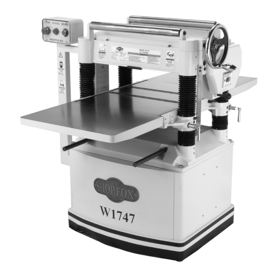
MODEL W1747
20" PLANER
OWNER'S MANUAL
Phone: (360) 734-3482 • Online Technical Support: tech-support@shopfox.biz
COPYRIGHT © SEPTEMBER, 2006 BY WOODSTOCK INTERNATIONAL, INC.
WARNING: NO PORTION OF THIS MANUAL MAY BE REPRODUCED IN ANY SHAPE OR FORM WITHOUT
THE WRITTEN APPROVAL OF WOODSTOCK INTERNATIONAL, INC.
Printed in China
#8426BL
Advertisement
Table of Contents

Related Manuals for Shop fox SHOP FOX W1747


Summary of Contents for Shop fox SHOP FOX W1747
- Page 1 OWNER'S MANUAL Phone: (360) 734-3482 • Online Technical Support: tech-support@shopfox.biz COPYRIGHT © SEPTEMBER, 2006 BY WOODSTOCK INTERNATIONAL, INC. WARNING: NO PORTION OF THIS MANUAL MAY BE REPRODUCED IN ANY SHAPE OR FORM WITHOUT THE WRITTEN APPROVAL OF WOODSTOCK INTERNATIONAL, INC.
- Page 2 ����������������������������������������������������������������������� �������������������������������������������������������������� ���������������������������������������������������������������������� �������������������������������������������������������������������� ������������������������ ����������������������������������������������������������������������� ������������������������������������������������������������������������ ������������������������������������������������������������������� ����������������������������������������������������������������� ���������������������������������������������������������������������� ����������������������������������������������� ���������������������������������������������������������������� �������������������������������������������������������������������� ������� �������������������������������������������������������������������� ����������������������������������������������������������������������� ���������������������������������������������������������������������� ������������������������������������� �� ���������������������������� �� ������������������������������������������������������������������ �� ���������������������������������������������������� ������������������������������������������������������������������ ������������������������������������������������������������������ �������������������������������������������������������������������� ��������������������������������������������������������������������� ��������������������������...
-
Page 3: Table Of Contents
Contents INTRODUCTION ....................3 Woodstock Technical Support ................3 Specifications ....................4 Controls and Features ..................5 SAFETY ......................6 Standard Safety Instructions ................6 Additional Safety Instructions for Planers ............. 8 ELECTRICAL ......................9 220V Operation ..................... 9 Extension Cords .................... 9 Grounding .................... - Page 4 SERVICE ......................26 General .....................26 Inspecting Knives ..................26 Setting/Replacing Knives ................27 Chain Tension ....................28 Table Parallelism ..................29 Rollers, Chip Breaker & Pressure Bar Heights ............31 Spring Tension .....................34 Chip Deflector Positioning ................35 Scale Calibration ..................35 Anti-Kickback Fingers ..................36 Pulley Alignment ..................37 W1747 Electrical Components .................38 W1747 Wiring Diagram ..................39 Troubleshooting ...................40...
-
Page 5: Introduction
Close attention to detail, ruggedly built parts and a rigid quality control program assure safe and reliable operation. Woodstock International, Inc. is committed to customer satisfaction. Our intent with this manual is to include the basic information for safety, setup, operation, maintenance, and service of this product. -
Page 6: Specifications
W1747 20" Planer Specifications Motor: Type ........TEFC Capacitor-Start Induction Horsepower ............... 5 HP Phase / Voltage ........Single-Phase / 220V Amps ................30 Cycle / RPM ...........60 Hertz / 3450 RPM Switch ......Magnetic with Thermal Overload Relay Power Transfer .......... Triple V-Belt Drive Bearings ...... -
Page 7: Controls And Features
W1747 20" Planer Controls and Features Figure 1. W1747 Controls and features. A. Control Box and Panel B. Return Rollers C. Table Height Handwheel D. Gearbox E. Speed Control Knob F. Table Height Scale G. Table Locks H. Lifting Bar Extension Wing Dust Hood K. -
Page 8: Safety
W1747 20" Planer SAFETY READ MANUAL BEFORE OPERATING MACHINE. FAILURE TO FOLLOW INSTRUCTIONS BELOW WILL RESULT IN PERSONAL INJURY. Indicates an imminently hazardous situation which, if not avoided, WILL result in death or serious injury. Indicates a potentially hazardous situation which, if not avoided, COULD result in death or serious injury. - Page 9 W1747 20" Planer 10. NEVER LEAVE WHEN MACHINE IS RUNNING. Turn power OFF and allow all moving parts to come to a complete stop before leaving machine unattended. 11. DO NOT USE IN DANGEROUS ENVIRONMENTS. DO NOT use machinery in damp, wet locations, or where any flammable or noxious fumes may exist.
-
Page 10: Additional Safety Instructions For Planers
W1747 20" Planer Additional Safety Instructions for Planers READ and understand this USE this and other machinery with caution entire instruction manual and respect. Always consider safety first, before using this machine. as it applies to your individual working Serious personal injury conditions. -
Page 11: Electrical
W1747 20" Planer ELECTRICAL 220V Operation The Model W1747 operates at 220V. Always connect this machine to a dedicated circuit with a verified ground, using the recommended circuit size listed at the bottom Electrocution or severe shock could of this page. occur if machine is not grounded. -
Page 12: Set Up
W1747 20" Planer SET UP Unpacking SUFFOCATION HAZARD! The SHOP FOX Model W1747 has been carefully pack- ® Immediately discard all aged for safe transporting. If you notice the machine has plastic bags and pack- been damaged, please contact your authorized SHOP ing materials to elimi- dealer immediately. -
Page 13: Machine Placement
If any parts are missing, examine the packaging for the when assembling, adjusting or operat- missing parts. For any missing parts, find the part num- ing equipment. ber in the back of this manual and contact Woodstock International, Inc. at (360) 734-3482 or at tech- support@shopfox.biz Machine Placement •... -
Page 14: Cleaning Machine
W1747 20" Planer Cleaning Machine The table and other unpainted parts of your planer are coated with a waxy grease that protects them from corro- sion during shipment. Clean this grease off with a solvent cleaner or citrus-based degreaser. DO NOT use chlorine- based solvents such as brake parts cleaner or acetone—if you happen to splash some onto a painted surface, you will ruin the finish. -
Page 15: Extension Wings
W1747 20" Planer Extension Wings Extension wings are heavy and could cause per- sonal injury if dropped during installation. Have an assistant hold the table while you fasten it to the planer. To attach the table extension wings, do these steps: 1. -
Page 16: Handwheel
W1747 20" Planer Handwheel To install the handwheel, do these steps: 1. Place the bushing on the handwheel shaft. 2. Insert the key into the shaft keyway. Main Power 3. Thread the handle into the handwheel. Switch 4. Place the handwheel on the shaft and secure it with the M12-1.75 hex nut and flat washer, as shown in Figure 6. -
Page 17: Gearbox Oil Level
W1747 20" Planer Gearbox Oil Level Before starting your machine for the first time, make sure the gearbox has oil. The proper oil level is just even with the bottom of the fill plug hole. The gearbox uses 80W-90W automotive grade gear oil. To check the gearbox oil level, do these steps: 1. -
Page 18: Test Run
W1747 20" Planer Test Run Complete this process once you have familiarized yourself with all instructions in this manual. The purpose of the test run is to make sure the motor is working properly before proceeding. To perform a test run, do these steps: 1. -
Page 19: Operations
W1747 20" Planer OPERATIONS General The Model W1747 will perform many types of operations that are beyond the scope of this manual. Many of these operations can be dangerous or deadly if performed incor- rectly. The instructions in this section are written with the under- standing that the operator has the necessary knowledge and skills to operate this machine. -
Page 20: Operation Tips
W1747 20" Planer 6. Measure your workpiece thickness and adjust the table height as necessary to take a lighter or heavier pass, depending on your needs. For most wood types, " per pass is a good cutting depth. Note: Any time you switch directions with the handwheel, there will be a small amount of back- lash—so the first crank of the handwheel after switching directions will be slightly less than... -
Page 21: Feed Speed
W1747 20" Planer Feed Speed The infeed and outfeed rollers power the stock through the planer while keeping boards flat and providing a con- sistent rate of movement. � � � The power feed features high/low feed rates. Use the different feed rates as stated below: Low Feed Rate ......Dimensioning Pass High Feed Rate ........ -
Page 22: Bed Rollers
W1747 20" Planer Bed Rollers Adjustment Height Range: 0.002"–0.020" The height of the bed rollers will vary, depending on the ��������������� type of material you intend to plane, but as a general rule keep the roller height within 0.002"–0.020" above the table (Figure 27). -
Page 23: Accessories
Dealer. If you do not have a dealer in your area, these products are also available through online deal- ers. Please call or e-mail Woodstock International Inc. Customer Service to get a current listing of deal- ers at: 1-800-545-8420 or at sales@woodstockint.com. - Page 24 W1747 20" Planer PLANER PAL Magnetic Planer Knife Setting Jigs. Our patented ® knife-setting system lets you set straight-type planer knives in per- fect alignment every time! You can shift nicked knives on 2 ⁄ "– 4" cutterheads to get a perfect cut with an accuracy of ±.002". Two jigs are needed for 15"–...
-
Page 25: Maintenance
W1747 20" Planer MAINTENANCE General SHOP FOX Regular periodic maintenance on your ® Model W1747 will ensure its optimum performance. Make a habit of inspecting your machine each time you use it. Check for the following conditions and repair or replace when necessary: •... -
Page 26: V-Belts
W1747 20" Planer V-Belts V-belt removal and replacement is simply a matter of loosening the V-belts, rolling them off of the pulleys, replacing them with new belts, then retensioning them. Always replace V-belts with a matched set of 3 belts, or belt tension may not be even among the 3 belts and may cause premature belt failure. -
Page 27: Lubrication
W1747 20" Planer Lubrication This planer uses sealed and pre-lubricated ball bearings that require no lubrication. The following is a list of parts that need lubrication: Column Lead screw Columns/Lead Screws: The four columns should be lubri- cated weekly with SAE 30W oil. Unfasten dust covers to gain access. -
Page 28: Service
If you require additional machine service not included in this section, please contact Woodstock International Technical Support at (360) 734-3482 or send e-mail to: tech-support@shopfox.biz. Inspecting Knives... -
Page 29: Setting/Replacing Knives
W1747 20" Planer Setting/Replacing Knives Setting the knives correctly is crucial to the proper operation of the planer and is very important in keeping the knives sharp. If one knife protrudes higher than the others, it will do the majority of the work, and thus, dull much faster than the others. -
Page 30: Chain Tension
W1747 20" Planer 6. Position the knife gauge over the knife as shown in Figure 17 and loosen the gib bolts until the knife is completely loose. 7. Jack Screws—Using a 3mm hex wrench, find the jack screws through the access holes in the cutterhead (Figure 19) and rotate the jack screws to raise or lower the knife. -
Page 31: Table Parallelism
W1747 20" Planer Table Parallelism Table parallelism is critical to the operation of the machine. As such, it is essential that the table is parallel with the cutterhead (within 0.002") from side-to-side, as ���������� illustrated in Figure 22. �������� �������� �����... - Page 32 W1747 20" Planer To adjust the table parallelism, do these steps: 1. DISCONNECT THE PLANER FROM THE POWER SOURCE! 2. Remove the motor access panel and locate the chain on the underside of the table. 3. Loosen the lock bolts and idler sprocket (see Chain Tension instructions on Page 28).
-
Page 33: Rollers, Chip Breaker & Pressure Bar Heights
W1747 20" Planer Rollers, Chip Breaker & Pressure Bar Heights Distance Below Knife Edge at *BDC: Infeed Roller ..........0.040" Chip Breaker ..........0.040" Pressure Bar ..........0.008" Outfeed Roller ........... 0.020" *BDC = Bottom Dead Center (see Figure 25). To ensure accurate results and make the adjustment pro- cess quicker and easier, we recommend using a Rotacator (see Page 21) for these adjustments. - Page 34 W1747 20" Planer 7. Adjust the height of the infeed roller on the same side as the Rotacator to the specification given at the beginning of this procedure, using the zero set- ting of the Rotacator as a reference point. Figure 27 shows the jam nut and set screw for adjusting the roller height.
- Page 35 W1747 20" Planer To adjust the height of the infeed and outfeed rollers, chip breaker and pressure bar using wood blocks and a feeler gauge, do these steps: ��� 1. Build the wood blocks by cutting a straight 6' long 2x4 in half.
-
Page 36: Spring Tension
W1747 20" Planer Spring Tension Roller spring tension must be adjusted so that roller pres- sure is uniform. Roller spring tension will vary, depending Tension Screws on the type of wood you plane. This is usually deter- #1 - #3 Adjust to ⁄... -
Page 37: Chip Deflector Positioning
W1747 20" Planer Chip Deflector Positioning The chip deflector keeps chips from falling onto the outfeed roller. Chip Deflector Gap Setting If Planer Used w/Dust Collector ......⁄ " If Planer Used w/o Dust Collector ....... ⁄ " To adjust the deflector position, do these steps: 1. -
Page 38: Anti-Kickback Fingers
W1747 20" Planer Anti-Kickback Fingers The Model W1747 provides an anti-kickback system as a safety feature. The anti-kickback fingers hang from a rod suspended across the cutter headstock. The anti-kickback fingers should be inspected regularly. Check the fingers (Figure 34) to ensure that they swing freely and easily. -
Page 39: Pulley Alignment
W1747 20" Planer Pulley Alignment Proper pulley alignment (see Figure 35) prevents pre- mature belt wear. The pulleys are properly aligned when they are parallel and in the same plane as each other. Use a straightedge on the edge of the pulleys to judge alignment. -
Page 40: W1747 Electrical Components
W1747 20" Planer W1747 Electrical Components START POWER STOP Figure 37. W1747 motor junction box. Figure 38. W1747 control panel. Figure 39. W1747 magnetic switch assembly. -38-... -
Page 41: W1747 Wiring Diagram
W1747 20" Planer W1747 Wiring Diagram ������������������������������������ ����������� ��������� �� �� �� �� �� �� ����� �� ������ ����� �� ����� ����� ���� ����� �� �� ��� �� ������ �� �� �� ���� �� ����� �� �� �� �� � ��... -
Page 42: Troubleshooting
W1747 20" Planer Troubleshooting This section covers the most common problems and corrections with this type of machine. WARNING! DO NOT make any adjustments until power is disconnected and moving parts have come to a complete stop! Motor & Machine Operation PROBLEM POSSIBLE CAUSE CORRECTIVE ACTION... - Page 43 W1747 20" Planer Cutting PROBLEM POSSIBLE CAUSE CORRECTIVE ACTION 1. Lower the bed rollers (Page 20). Excessive snipe (gouge in 1. One or both of the bed rollers are the end of the board that set too high. is uneven with the rest of 2.
-
Page 44: Headstock Assembly Parts Breakdown
W1747 20" Planer Headstock Assembly Parts Breakdown -42-... -
Page 45: Headstock Assembly Parts List
W1747 20" Planer Headstock Assembly Parts List PART�# DESCRIPTION PART�# DESCRIPTION X1747101 ROUND�KNOB�5/16-18 X1747141 SHAFT X1747102 V-BELT�COVER XPN01M HEX�NUT�M6-1 XPVM59 V-BELT�M59�3L590 XPSS25M SET�SCREW�M6-1�X�20 X1747104 STUD XPFH30M FLAT�HD�SCR�M5-.8�X�8 XPB09M HEX�BOLT�M8-1.25�X�20 X1747145 DEPTH�LIMITER X1747106 FENDER�WASHER�8MM X1747146 INDICATOR XPFS02M FLANGE�SCREW�M6-1�X�12 XPSB50M CAP�SCREW�M5-.8�X�10 X1747108 PULLEY�GUARD XPS14M PHLP�HD�SCR�M6-1�X�12... - Page 46 W1747 20" Planer PART�# DESCRIPTION PART�# DESCRIPTION XPN09M HEX�NUT�M12-1.75 X1747208 GEAR X1747182 INFEED�ROLLER X1747209 GEAR X1747183 CHAIN�� XPFS14M FLANGE�SCREW�M6-1�X�16 XPSB05M CAP�SCREW�M8-1.25�X�50 X1747211 SHAFT XP6204 BALL�BEARING�6204ZZ X1747212 COMPRESSION�SPRING X1747186 GEAR X1747213 BALL�6MM XPSB06M CAP�SCREW�M6-1�X�25 X1747214 OIL�SEAL�25�X�47�X�6 XP6201 BALL�BEARING�6201 XP6204 BALL�BEARING�6204ZZ�� X1747189 GEAR X1747216 CLUTCH...
-
Page 47: Table, Base, And Columns Parts Breakdown
W1747 20" Planer Table, Base, and Columns Parts Breakdown ��� ��� ��� ��� ��� ��� ��� ��� ��� ��� ��� ��� ��� ��� ��� ��� ��� ��� ��� ��� ��� ��� ��� ��� ��� ��� ��� ��� ��� ��� ��� ���... -
Page 48: Table, Base, And Columns Parts List
W1747 20" Planer Table, Base, and Columns Parts List PART�# DESCRIPTION PART�# DESCRIPTION XPW01M FLAT�WASHER�8MM X1747264 SPROCKET XPSS13M SET�SCREW�M10-1.5�X�12 XPR05M EXT�RETAINING�RING�15MM XPR03M EXT�RETAINING�RING�12MM XP6202 BEARING�6202ZZ X1747214 OIL�SEAL�25�X�47�X�6 XPR21M INT�RETAINING�RING�35MM X1747219 EXTENSION�WING X1747268 SPROCKET XPB07M HEX�BOLT�M8-1.25�X�25 XPW04M FLAT�WASHER�10MM XPSS09M SET�SCREW�M8-1.25�X�20 XPN08M HEX�NUT�M10-1.25 X1747222 LOCKING�BOLT... -
Page 49: Stand/Motor Assembly Parts Breakdown
W1747 20" Planer Stand/Motor Assembly Parts Breakdown ����� ����� ����� ����� ����� ����� ����� ��� ��� ��� ��� ��� ��� ��� ��� ��� ��� ��� ��� ����� ��� ��� ��� ��� ��� ��� ��� ��� ��� ��� ��� ��� ��� ���... -
Page 50: Stand/Motor Assembly Parts List
W1747 20" Planer Stand/Motor Assembly Parts List PART�# DESCRIPTION PART�# DESCRIPTION X1747106 FENDER�WASHER�8MM X1747251 INDICATOR�LIGHT�(RED) XPFS02M FLANGE�SCREW�M6-1�X�12 X1747252 SWITCH�PLATE XPW03M FLAT�WASHER�6MM X1747253 SWITCH�BOX XPSS14M SET�SCREW�M8-1.25�X�12 X1747254 SWITCH�ELBOW�BRACKET XPN09M HEX�NUT�M12-1.75 XPW06M FLAT�WASHER�12MM XPFH06M FLAT�HD�SCR�M6-1�X�20 X1747284 MOTOR�BRACKET X1747235 COVER X1747285 COLLAR X1747236 STRAIN�RELIEF XPB15M HEX�BOLT�M8-1.25�X�40... -
Page 51: Warning Label Placement And Parts List
MUST maintain the original location and readability of all labels on this machine. If any label is removed or becomes unreadable, REPLACE that label before allowing the machine to enter service again. Contact Woodstock International, Inc. at (360) 734-3482 or www. shopfoxtools.com to order new labels. - Page 52 ® with the provisions of any law or acts. In no event shall Woodstock International, Inc.'s liability under this warranty exceed the purchase price paid for the product, and any legal actions brought against Woodstock International, Inc. shall be tried in the State of Washington, County of Whatcom. We shall in no event be liable for death, injuries to persons or property or for incidental, contingent, special or consequential damages arising from the use of our products.
- Page 53 W1747 20" Planer Warranty Registration Name ___________________________________________________________________________________ Street __________________________________________________________________________________ City _________________________ State ___________________________Zip ________________________ Phone # ______________________ Email __________________________Invoice # ___________________ Model #_________Serial #______________Dealer Name__________________Purchase Date___________ The following information is given on a voluntary basis. It will be used for marketing purposes to help us develop better products and services.
- Page 54 FOLD ALONG DOTTED LINE Place Stamp Here WOODSTOCK INTERNATIONAL INC. P.O. BOX 2309 BELLINGHAM, WA 98227-2309 FOLD ALONG DOTTED LINE TAPE ALONG EDGES--PLEASE DO NOT STAPLE...
Need help?
Do you have a question about the SHOP FOX W1747 and is the answer not in the manual?
Questions and answers