Table of Contents
Advertisement
Quick Links
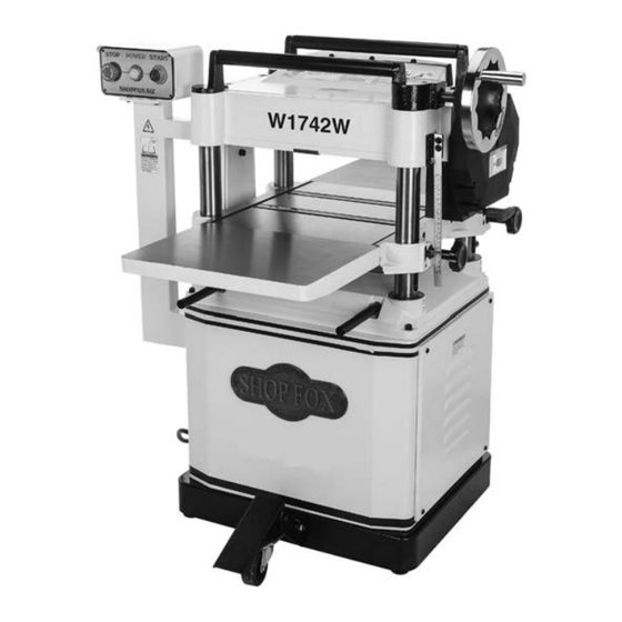
MODEL W1742W, W1742SW,
W1754W, W1754SW
15" & 20" PLANERS
OWNER'S MANUAL
(FOR MODELS MANUFACTURED SINCE 9/15)
Phone: (360) 734-3482 • Online Technical Support: techsupport@woodstockint.com
COPYRIGHT © JANUARY, 2016 BY WOODSTOCK INTERNATIONAL, INC.
WARNING: NO PORTION OF THIS MANUAL MAY BE REPRODUCED IN ANY SHAPE OR FORM WITHOUT
THE WRITTEN APPROVAL OF WOODSTOCK INTERNATIONAL, INC.
#17486WK Printed in China
Advertisement
Table of Contents

Related Manuals for Shop fox W1742W


Summary of Contents for Shop fox W1742W
- Page 1 MODEL W1742W, W1742SW, W1754W, W1754SW 15" & 20" PLANERS OWNER'S MANUAL (FOR MODELS MANUFACTURED SINCE 9/15) Phone: (360) 734-3482 • Online Technical Support: techsupport@woodstockint.com COPYRIGHT © JANUARY, 2016 BY WOODSTOCK INTERNATIONAL, INC. WARNING: NO PORTION OF THIS MANUAL MAY BE REPRODUCED IN ANY SHAPE OR FORM WITHOUT THE WRITTEN APPROVAL OF WOODSTOCK INTERNATIONAL, INC. #17486WK Printed in China...
- Page 2 This manual provides critical safety instructions on the proper setup, operation, maintenance, and service of this machine/tool. Save this document, refer to it often, and use it to instruct other operators. Failure to read, understand and follow the instructions in this manual may result in fire or serious personal injury—including amputation, electrocution, or death.
-
Page 3: Table Of Contents
Troubleshooting ......... 45 Items Needed for Setup ....... 13 Electrical Safety Instructions ....47 Inventory ........14 W1742W & W1742SW Wiring Diagram ..48 Cleaning Machine ....... 15 W1754W & W1754SW Wiring Diagram ..49 Machine Placement ......16 Lifting & Moving ........ 17 PARTS:.W1742W.&.W1742SW.... -
Page 4: Introduction
This information is required for Machine.Differences all Tech Support calls. • Models W1742W and W1742SW are 3 HP, 15" planers. MODEL XXXX MACHINE NAME — Model.W1742W has a 3-knife cutterhead. -
Page 5: Machine Specifications
W1742W, W1742SW, W1754W, W1754SW (Mfd. Since 9/15) MACHINE SPECIFICATIONS © Woodstock International, Inc. • Phone #: (800) 840-8420 • Web: www.shopfox.biz Model Number W1742W W1742SW W1754W W1754SW Product Dimensions Weight 532 lbs. 534 lbs 781 lbs. 790 lbs. Width (side-to-side) x Depth 38"... - Page 6 W1742W, W1742SW, W1754W, W1754SW (Mfd. Since 9/15) Model Number W1742W W1742SW W1754W W1754SW Main Specifications Planer Size 15 in. 20 in. Max. Cut Width 15 in. 20 in. Max. Stock Thickness 8 in. Min. Stock Thickness ⁄ Min. Stock Length ⁄...
-
Page 7: Identification
W1742W, W1742SW, W1754W, W1754SW (Mfd. Since 9/15) Identification Become familiar with the names and locations of the controls and features shown below to better understand the instructions in this manual. Return Rollers Control Panel Table Height Handwheel Gearbox Feed Rate... -
Page 8: Controls & Components
W1742W, W1742SW, W1754W, W1754SW (Mfd. Since 9/15) Controls.&.Components Refer to the Figures.1–3 and the following descriptions to become familiar with the basic controls and components of this machine. Understanding these items and how they work will help you understand the rest of the manual and stay safe when operating this machine. -
Page 9: Internal Components
W1742W, W1742SW, W1754W, W1754SW (Mfd. Since 9/15) Internal.Components FRONT REAR Workpiece Figure.4. Workpiece path and major planing components (side cutaway view). A. Anti-Kickback.Fingers: Provide additional F.. Pressure.Bar.(W1754W & W1754SW):. safety for the operator. Stabilizes the workpiece as it leaves the cutterhead and assists in deflecting wood B. -
Page 10: Safety
W1742W, W1742SW, W1754W, W1754SW (Mfd. Since 9/15) SAFETY SAFETY For.Your.Own.Safety, Read.Manual.Before.Operating.Machine The. purpose. of. safety. symbols. is. to. attract. your. attention. to. possible. hazardous. conditions.. This. manual.uses.a.series.of.symbols.and.signal.words.intended.to.convey.the.level.of.importance.of.the. safety.messages..The.progression.of.symbols.is.described.below..Remember.that.safety.messages.by. themselves. do. not. eliminate. danger. and. are. not. a. substitute. for. proper. accident. prevention. mea- sures—this.responsibility.is.ultimately.up.to.the.operator! - Page 11 W1742W, W1742SW, W1754W, W1754SW (Mfd. Since 9/15) WEARING.PROPER.APPAREL..Do not wear FORCING.MACHINERY..Do not force machine. It clothing, apparel, or jewelry that can become will do the job safer and better at the rate for entangled in moving parts. Always tie back which it was designed.
-
Page 12: Additional Safety For Planers
W1742W, W1742SW, W1754W, W1754SW (Mfd. Since 9/15) Additional.Safety.for.Planers MAIN.PLANER.INJURY.RISKS..Familiarize yourself BODY.PLACEMENT..Stand to one side of planer with the main injury risks associated with during the entire operation to avoid getting planers—always use common sense and good hit if kickback occurs. -
Page 13: Electrical
W1742W, W1742SW, W1754W, W1754SW (Mfd. Since 9/15) ELECTRICAL Circuit.Requirements This machine must be connected to the correct size and The. machine. must. be. properly. set. up. type of power supply circuit, or fire or electrical damage before. it. is. safe. to. operate.. DO. NOT. -
Page 14: Grounding Requirements
W1742W, W1742SW, W1754W, W1754SW (Mfd. Since 9/15) Grounding.Requirements This machine MUST be grounded. In the event of certain types of malfunctions or breakdowns, grounding provides a path of least resistance for electric current to travel—in The. machine. must. be. properly. set. up. -
Page 15: Setup
Hex Wrenches 3, 4, 5, 6, 8mm .....1 Ea. this. machine.. Otherwise,. • Straightedge 4' ..........1 serious. personal. injury. • Dust Collection System ........1 may.occur.. • 4" Dust Hose w/Clamps (W1742W & W1742SW) ..1 • 5" Dust Hose w/Clamps (W1754W & W1754SW) ..1 -13-... -
Page 16: Inventory
W1742W, W1742SW, W1754W, W1754SW (Mfd. Since 9/15) Inventory The following is a list of items shipped with your machine. Before beginning setup, lay these items out and inventory them. Note: If you cannot find an item on this list, carefully check around/inside the machine and packaging materials. -
Page 17: Cleaning Machine
W1742W, W1742SW, W1754W, W1754SW (Mfd. Since 9/15) Cleaning.Machine To prevent corrosion during shipment and storage of your machine, the factory has coated the bare metal surfaces of your machine with a heavy-duty rust prevention compound. Gasoline.and.petroleum. products.have.low.flash. If you are unprepared or impatient, this compound can points.and.can.explode. -
Page 18: Machine Placement
W1742W, W1742SW, W1754W, W1754SW (Mfd. Since 9/15) Machine.Placement Weight.Load Physical.Environment Refer to the Machine.Specifications for the The physical environment where your machine is weight of your machine. Make sure that the operated is important for safe operation and the surface upon which the machine is placed will longevity of its components. -
Page 19: Lifting & Moving
W1742W, W1742SW, W1754W, W1754SW (Mfd. Since 9/15) Lifting.&.Moving The planer is equipped with four lifting bars that extend in order to lift and place the planer, as shown in Figure.11. The rear wheels and front feet mount to the bottom of the machine. -
Page 20: Assembly
W1742W, W1742SW, W1754W, W1754SW (Mfd. Since 9/15) Assembly To.assemble.planer,.do.these.steps: Adjustment Set Screws 1. W1742W.&.W1742SW: Attach each table extension (1 of 2) wing to planer table with (2) pre-installed M8-1.25 x 25 cap screws, 8mm lock washers, and 8mm flat washers,. Do not fully tighten cap screws at this time. -
Page 21: Dust Collection
To connect the machine to a dust collection system, fit port. a 4" dust hose (W1742W & W1742SW) or a 5" dust hose (W1754W & W1754SW) over the dust port, and secure in place with a hose clamp (see Figure.19). Tug the hose to make sure it does not come off. -
Page 22: Checking Gearbox Oil Level
W1742W, W1742SW, W1754W, W1754SW (Mfd. Since 9/15) Checking.Gearbox.Oil. Level Before starting your machine for the first time, make sure the gearbox has oil. The proper oil level is just even with the bottom of the fill plug hole. The gearbox uses ISO 320 or SAE 140 gear oil. -
Page 23: Test Run
W1742W, W1742SW, W1754W, W1754SW (Mfd. Since 9/15) Test.Run Once assembly is complete, test run the machine to ensure it is properly connected to power and safety components are functioning properly. Serious. injury. or. death. can. result. from. using. this. machine. BEFORE. -
Page 24: Operations
W1742W, W1742SW, W1754W, W1754SW (Mfd. Since 9/15) OPERATIONS General This machine will perform many types of operations that are beyond the scope of this manual. Many of these operations can be dangerous or deadly if performed incorrectly. The instructions in this section are written with the understanding that the operator has the necessary knowledge and skills to operate this machine. -
Page 25: Workpiece Inspection
W1742W, W1742SW, W1754W, W1754SW (Mfd. Since 9/15) Workpiece.Inspection Wood.Types Some workpieces are not safe to use or may The species of wood, as well as its condition, require modification before they are. Before. greatly affects the depth of cut the planer can cutting,.inspect.all.workpieces.for.the. -
Page 26: Planing Tips
W1742W, W1742SW, W1754W, W1754SW (Mfd. Since 9/15) Planing.Tips Cutting.Problems • Inspect your lumber for twisting or cupping, Below is a list of wood characteristics you and surface one face on a jointer if may encounter when planing. The following necessary before planing workpiece. - Page 27 W1742W, W1742SW, W1754W, W1754SW (Mfd. Since 9/15) Chip.Marks.or.Indentations Rippled.Cut. Problem: Chip indentation or chip bruising is Problem: Regularly spaced indentations across the result of wood chips not being thrown away face of workpiece are caused by excessive from the cutterhead and out of the machine.
-
Page 28: Depth Of Cut
W1742W, W1742SW, W1754W, W1754SW (Mfd. Since 9/15) Depth.of.Cut Table.Movement.per.Handwheel.Revolution Table One Full Revolution ......... ⁄ " Height Handwheel The depth of cut on a planer means the amount of material that is removed from the top of the workpiece as it passes underneath the cutterhead. -
Page 29: Bed Roller Height
W1742W, W1742SW, W1754W, W1754SW (Mfd. Since 9/15) Bed.Roller.Height Bed Roller Height Range ......0.002"–0.020" 0.002"–0.020" Table The correct height of the bed rollers will vary, depending on the type of material you intend to plane. However, as a general rule, keep the bed roller height within 0.002"–... -
Page 30: Setting Feed Rate
(see Page.29). cuts. The knife-setting jig that is included with the Model W1742W/W1754W is designed to set the knives 0.059" higher than the cutterhead surface. To. maintain. accurate. and. consistent. Note:.If you need to replace or sharpen a knife, you can planing.results,.we.do.not.recommend. - Page 31 W1742W, W1742SW, W1754W, W1754SW (Mfd. Since 9/15) Tools.Needed. Loosen Phillips Screwdriver #2 .........1 Knife Tighten Open-End Wrench 12, 13mm ......1 Ea. Hex Wrench 3mm ..........1 Jack Screw Knife-Setting Jig ..........1 To.adjust.height.of.knives,.do.these.steps: 1. DISCONNECT MACHINE FROM POWER! 2. Remove dust port and top cover to expose cutterhead.
-
Page 32: Rotating/Replacing Cutterhead Inserts
W1742W, W1742SW, W1754W, W1754SW (Mfd. Since 9/15) Rotating/Replacing. Cutterhead.Inserts. (W1742SW.&.W1754SW) The spiral cutterhead is equipped with indexable carbide inserts that can be rotated to reveal any one of their four cutting edges. If one edge of the insert becomes dull or damaged, simply rotate it 90°... -
Page 33: Accessories
W1742W, W1742SW, W1754W, W1754SW (Mfd. Since 9/15) ACCESSORIES Planer.Accessories The following Planer accessories may be available through your local Woodstock International Inc. Dealer. If you do not have a dealer in your area, these products are also available through online dealers. -
Page 34: Maintenance
W1742W, W1742SW, W1754W, W1754SW (Mfd. Since 9/15) MAINTENANCE Schedule Every.160.Hours.of.Operation: • Check/tension/replace V-belts (Page.35). • Clean/vacuum dust buildup from inside cabinet and off motor. • Lubricate table height worm gear MAKE. SURE. that. your. (Page.33). machine. is. unplugged. • Lubricate table height chain/sprockets during. - Page 35 W1742W, W1742SW, W1754W, W1754SW (Mfd. Since 9/15) Feed.Roller.Bushings Oil Type ........ISO 68 Equivalent Oil Amount ..........2–3 Drops Frequency ......Every 8 Hours of Operation Lubricate Here The infeed and outfeed rollers rotate inside bushing blocks on both ends of the rollers. Add 2–3 drops of ISO...
- Page 36 W1742W, W1742SW, W1754W, W1754SW (Mfd. Since 9/15) Table.Height.Chain.&.Sprockets Grease Type ......Lithium-Based NLGI#2 Frequency ..... Every 160 Hours of Operation The table leadscrews are synchronized by the table height chain and sprockets located underneath the planer base (see Figure.36). Use shop rags and mineral spirits to clean away debris and grime, then brush on a light coat of multi-purpose grease to the chain and sprockets.
-
Page 37: Service
W1742W, W1742SW, W1754W, W1754SW (Mfd. Since 9/15) SERVICE General This section covers the most common service adjustments or procedures that may need to be made during the life of your machine. If you require additional machine service not included in this section, please contact Woodstock International Technical Support at (360) 734-3482 or send e-mail to: techsupport@woodstockint.com. -
Page 38: Tensioning Table Height Chain
W1742W, W1742SW, W1754W, W1754SW (Mfd. Since 9/15) 3. Remove front cabinet cover to access motor, as shown in Figure.40. 4. If V-belts need to be replaced, raise motor to release belt tension (see next step for instructions), roll them off pulleys, then replace with a matched set of three belts. -
Page 39: Feed Rollers, Chip Breaker & Pressure Bar Heights
W1742W, W1742SW, W1754W, W1754SW (Mfd. Since 9/15) Feed.Rollers,.Chip. Breaker.&.Pressure.Bar. Heights It is essential that the feed rollers, chip breaker, and Chip Pressure pressure bar are set at the correct distance below the Breaker (Bottom Dead Center) cutterhead knives/inserts at BDC (bottom dead center) - Page 40 W1742W, W1742SW, W1754W, W1754SW (Mfd. Since 9/15) 5. Using your Rotacator, find bottom dead center (BDC) of any knife/insert edge by slowly rocking cutterhead pulley back and forth, then set Rotacator dial to "0" (see Figure.44). 6. Move feed speed knob to neutral position to allow infeed roller to freely rotate.
- Page 41 W1742W, W1742SW, W1754W, W1754SW (Mfd. Since 9/15) Using.Wood.Blocks Tools.Needed. Phillips Screwdriver #2 .........1 Hex Wrench 3mm ..........1 Open-End Wrench or Socket 10mm ......1 2x4 6' Long ............1 Feeler Gauge Set ..........1 To.use.wood.blocks,.do.these.steps: 1. Build wood blocks by cutting a straight 6-foot-long 2x4 in half.
- Page 42 W1742W, W1742SW, W1754W, W1754SW (Mfd. Since 9/15) 10. Loosen jam nuts and set screws on each side of Roller infeed roller (see Figure.49). Bushing Block 11.. Using a feeler gauge, adjust set screw so it is 0.020" from roller bushing block (see Figure.49), then tighten jam nut.
-
Page 43: Adjusting Roller Spring Tension
W1742W, W1742SW, W1754W, W1754SW (Mfd. Since 9/15) Adjusting.Roller.Spring. Tension The infeed and outfeed rollers keep the workpiece moving through the planer. There are springs that exert downward pressure on the rollers while still allowing them to raise with an uneven workpiece surface. Proper roller spring tension is crucial to keep the workpiece moving through the planer during operation. -
Page 44: Positioning Chip Deflector
W1742W, W1742SW, W1754W, W1754SW (Mfd. Since 9/15) Positioning.Chip.Deflector Chip Deflector Gap Setting ......... ⁄ " When properly distanced from the cutterhead, the chip deflector directs the chips into the dust hood, and keeps them from falling onto the outfeed roller and being pressed into the workpiece. -
Page 45: Calibrating Table Height Scale
W1742W, W1742SW, W1754W, W1754SW (Mfd. Since 9/15) Calibrating.Table.Height. Scale Although correctly set at the factory, the table height scale can be adjusted for accuracy if it becomes necessary. Tools.Needed. Hex Wrench 4mm ..........1 Screws Scrap Piece of Stock ..........1 Calipers ............1 To.re-position.scale,.do.these.steps:... -
Page 46: Pulley Alignment
W1742W, W1742SW, W1754W, W1754SW (Mfd. Since 9/15) Pulley.Alignment Proper pulley alignment prevents premature V-belt wear and unnecessary load on the motor. It also ensures efficient and effective transfer of power. The pulleys are properly aligned when they are parallel and in the same plane as each other. -
Page 47: Troubleshooting
W1742W, W1742SW, W1754W, W1754SW (Mfd. Since 9/15) Troubleshooting The following troubleshooting tables cover common problems that may occur with this machine. If you need replacement parts or additional troubleshooting help, contact our Technical Support. Note: Before contacting Tech Support, find the machine serial number and manufacture date, and if available, your original purchase receipt. - Page 48 W1742W, W1742SW, W1754W, W1754SW (Mfd. Since 9/15) Machine Operation PROBLEM POSSIBLE.CAUSE CORRECTIVE.ACTION 1. Lower bed rollers (Page 37). Excessive snipe 1. One or both of bed rollers are set too high. (gouge in end 2. Outfeed extension slopes down or is not level 2.
-
Page 49: Electrical Safety Instructions
W1742W, W1742SW, W1754W, W1754SW (Mfd. Since 9/15) Electrical.Safety.Instructions These pages are current at the time of printing. However, in the spirit of improvement, we may make changes to the electrical systems of future machines. Compare the manufacture date of your machine to the one stated in this manual, and study this section carefully. -
Page 50: W1742W & W1742Sw Wiring Diagram
W1742W, W1742SW, W1754W, W1754SW (Mfd. Since 9/15) W1742W.&.W1742SW.Wiring.Diagram Pedestal-Mounted ON/OFF Switch Stop Button Power Indicator Start Button Light GLY37 220V GLY37 220V AD-11-25/40-1G 13NO 220V Contactor TECO CU-11 220V 14NO TRIP IND. 11.3 TECO Relay Read TEST RHU-16K1 Page 47... -
Page 51: W1754W & W1754Sw Wiring Diagram
W1742W, W1742SW, W1754W, W1754SW (Mfd. Since 9/15) W1754W.&.W1754SW.Wiring.Diagram Pedestal-Mounted ON/OFF Switch Stop Button Power Indicator Start Button Light GLY37 220V GLY37 220V AD-11-25/40-1G 13NO 220V Contactor TECO CU-18 220V 14NO Read Page 47 STOP TRIP IND. 21.5 Before Wiring 17.5... -
Page 52: Parts:.w1742W.&.W1742Sw
W1742W, W1742SW, W1754W, W1754SW (Mfd. Since 9/15) PARTS:.W1742W.&.W1742SW Headstock 21A (W1742W Only) 30 17 W1742SW Only W1742W Only 85-1 85-2 W1742SW Only -50-... - Page 53 HEX WRENCH 6MM X1742W040 GIB SCREW M8-1.25 X 10 (W1742W) X1742W088 HEX WRENCH 5MM X1742W041 PLANER KNIVES 15" X 1" X 1/8" 3-PK (W1742W) X1742W089 HEX WRENCH 4MM X1742W042 FLAT HD CAP SCR M5-.8 X 10 (W1742W) X1742W090 HEX WRENCH 3MM...
-
Page 54: Table
W1742W, W1742SW, W1754W, W1754SW (Mfd. Since 9/15) Table REF PART # DESCRIPTION REF PART # DESCRIPTION X1742W101 MAIN TABLE X1742W111 SET SCREW M8-1.25 X 12 X1742W102 POINTER X1742W112 LOCKING ROD X1742W103 FLAT WASHER 5MM X1742W113 LOCK SLEEVE X1742W104 CAP SCREW M5-.8 X 10... -
Page 55: Base
W1742W, W1742SW, W1754W, W1754SW (Mfd. Since 9/15) Base REF PART # DESCRIPTION REF PART # DESCRIPTION X1742W201 BASE X1742W216 BALL BEARING 6002ZZ X1742W202 SCALE COLUMN X1742W217 INT RETAINING RING 32MM X1742W203 COLUMN X1742W218 SPACER 12.5 X 19 X 4MM X1742W204... -
Page 56: Gearbox
W1742W, W1742SW, W1754W, W1754SW (Mfd. Since 9/15) Gearbox REF PART # DESCRIPTION REF PART # DESCRIPTION X1742W301 GEARBOX X1742W318 GEARBOX COVER GASKET X1742W302 OIL SEAL 25 X 40 X 7 X1742W319 GEARBOX COVER X1742W303 BALL BEARING 6204ZZ X1742W320 KEY 5 X 5 X 40... -
Page 57: Feed Gearing
W1742W, W1742SW, W1754W, W1754SW (Mfd. Since 9/15) Feed.Gearing REF PART # DESCRIPTION REF PART # DESCRIPTION 401 X1742W401 SPROCKET 32T 414 X1742W414 EXTENSION SPRING 1 X 8 X 26.5 402 X1742W402 FENDER WASHER 6MM 415 X1742W415 SPRING BRACKET 403 X1742W403 CAP SCREW M6-1 X 16... -
Page 58: Cabinet Stand
W1742W, W1742SW, W1754W, W1754SW (Mfd. Since 9/15) Cabinet.Stand 504-3 504-1 504-2 504-2 504-4 504-5 504-6 504-9 504-7 504-8 504-9 545-2 545-4 545-1 545-1 545-3 545-5 -56-... - Page 59 W1742W, W1742SW, W1754W, W1754SW (Mfd. Since 9/15) Cabinet.Stand.Parts.List REF PART # DESCRIPTION REF PART # DESCRIPTION X1742W501 STAND X1742W526 FOOT PEDAL CASTER BASE X1742W502 BACK COVER X1742W527 INT RETAINING RING 35MM X1742W503 PHLP HD SCR M6-1 X 16 X1742W528 BALL BEARING 6202ZZ...
-
Page 60: Parts:.w1754W.&.W1754Sw
W1742W, W1742SW, W1754W, W1754SW (Mfd. Since 9/15) PARTS:.W1754W.&.W1754SW Headstock (W1754W Only) W1754W Only 89-1 89-2 W1754SW Only W1754SW Only -58-... - Page 61 W1742W, W1742SW, W1754W, W1754SW (Mfd. Since 9/15) Headstock.Parts.List REF PART # DESCRIPTION REF PART # DESCRIPTION X1754W002 REVOLVING HANDLE 80L, M10-1.5 X 18 X1754W048 FLAT WASHER 8MM X1754W003 HANDWHEEL TYPE-14 200D X 12B-K X M10-1.5 X1754W049 PLANER KNIVES 20" X 1" X 1/8" 3-PK (W1754W)
-
Page 62: Table
W1742W, W1742SW, W1754W, W1754SW (Mfd. Since 9/15) Table REF PART # DESCRIPTION REF PART # DESCRIPTION X1754W101 MAIN TABLE X1754W111 SET SCREW M6-1 X 12 X1754W102 FLAT WASHER 5MM X1754W112 SET SCREW M6-1 X 16 X1754W103 CAP SCREW M5-.8 X 10... -
Page 63: Base
W1742W, W1742SW, W1754W, W1754SW (Mfd. Since 9/15) Base REF PART # DESCRIPTION REF PART # DESCRIPTION X1754W201 BASE X1754W217 FLAT WASHER 10MM X1754W202 SET SCREW M10-1.5 X 12 X1754W218 HEX NUT M10-1.5 X1754W203 COLUMN X1754W219 FLAT WASHER 8MM X1754W204 SCALE COLUMN X1754W220 HEX BOLT M8-1.25 X 20... -
Page 64: Gearbox
W1742W, W1742SW, W1754W, W1754SW (Mfd. Since 9/15) Gearbox REF PART # DESCRIPTION REF PART # DESCRIPTION X1754W301 GEARBOX X1754W318 GEARBOX COVER GASKET X1754W302 OIL SEAL 25 X 40 X 7 X1754W319 GEARBOX COVER X1754W303 BALL BEARING 6204ZZ X1754W320 KEY 5 X 5 X 40... -
Page 65: Feed Gearing
W1742W, W1742SW, W1754W, W1754SW (Mfd. Since 9/15) Feed.Gearing REF PART # DESCRIPTION REF PART # DESCRIPTION 401 X1754W401 SPROCKET 32T 414 X1754W414 EXTENSION SPRING 1 X 8 X 26.5 402 X1754W402 FENDER WASHER 6MM 415 X1754W415 SPRING BRACKET 403 X1754W403 CAP SCREW M6-1 X 16... -
Page 66: Cabinet Stand
W1742W, W1742SW, W1754W, W1754SW (Mfd. Since 9/15) Cabinet.Stand 504-1 504-2 504-2 504-3 504-4 504-5 504-6 504-7 504-9 504-8 504-9 6 13 545-2 545-4 545-1 545-1 545-3 545-5 -64-... - Page 67 W1742W, W1742SW, W1754W, W1754SW (Mfd. Since 9/15) Cabinet.Stand.Parts.List PART # DESCRIPTION REF PART # DESCRIPTION X1754W501 STAND X1754W526 FOOT PEDAL CASTER BASE X1754W502 BACK COVER X1754W527 INT RETAINING RING 35MM X1754W503 PHLP HD SCR M6-1 X 16 X1754W528 BALL BEARING 6202ZZ...
-
Page 68: Parts:.labels.&.Cosmetics
Always wear safety Disconnect power 20 FPM 121x 13mm Neutral 16 FPM FOR SHOP FOX MACHINES ONLY! DO NOT REPRODUCE OR CHANGE THIS ARTWORK WITHOUT Only shift gearbox when (800) 840-8420. available, DO NOT use glasses, ear protection, OWNER’S MANUAL... - Page 69 W1742W/SW-W1754W/SW (Mfd. Since 9/15)
- Page 70 Fold along dotted lIne place stamp Here Woodstock international inc. p.o. box 2309 bellingham, Wa 98227-2309 Fold along dotted lIne tape along edges--please do not staple...
-
Page 71: Warranty
Woodstock International, Inc. will repair, replace, or arrange for a dealer refund, at its expense and option, the Shop Fox machine or machine part proven to be defective for its designed and intended use, provided that the original owner returns the product prepaid to an authorized warranty or repair facility as designated by our Bellingham, Washington office with proof of their purchase of the product within two years, and provides Woodstock International, Inc. - Page 72 High Quality Machines and Tools Woodstock International, Inc. carries thousands of products designed to meet the needs of today's woodworkers and metalworkers. Ask your dealer about these fine products:...
Need help?
Do you have a question about the W1742W and is the answer not in the manual?
Questions and answers
How to remove pulley from front of motor on shop fox w1742 planer
The provided context does not contain specific instructions for removing the pulley from the front of the motor on a Shop Fox W1742 planer. However, it does mention accessing the motor by removing the front cabinet cover and adjusting the V-belt tension. Based on general mechanical procedures, pulley removal typically involves loosening the set screw(s) on the pulley hub and using a puller tool if necessary. If detailed steps are required, refer to the machine’s manual for precise instructions.
This answer is automatically generated