Table of Contents
Advertisement
Advertisement
Table of Contents

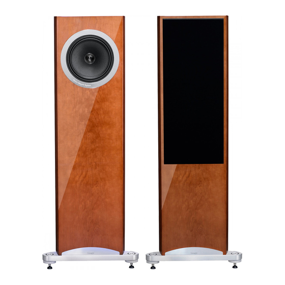
Summary of Contents for Tannoy Definition DC10A
- Page 1 O WNE R’S MA NU A L DEFINITION DC10A OWNER’S MANUAL_01...
-
Page 2: Table Of Contents
If you suspect a problem with a Tannoy product then, in the first instance, discuss it with your Tannoy dealer. If you require further assistance then we ask that you deal directly with your local Tannoy distributor. If you cannot locate your distributor please contact Tannoy Customer Services, at the address given below. -
Page 3: Introduction
From instrument amplifiers to guitar pick-ups, Alnico is revered across the music industry for its musicality and dynamics as well as its ability to resolve low level information and texture in the music. Tannoy has long used Alnico drivers in its range topping loudspeakers to best reproduce every note and intonation that the musician intended - a realism rarely achieved by ceramic ferrite motor systems. -
Page 4: Amplifier Choice
AMPLIFIeR cHoIce Consult the product specification as this clearly shows the acceptable power range for amplifier matching to your speakers. The high peak power handling of Tannoy loudspeakers permits responsible use with more powerful amplifiers - please read the Warranty. -
Page 5: Mass Loading
MAss LoADInG These loudspeakers are designed to be mass loaded, if wished, to lower the centre of gravity and improve stability, resulting in improved sound quality. To do so, remove the 4 screws securing the access plate to the bottom of the loudspeaker. -
Page 6: Connection In Bi-Wire Mode
(Method illustrated on all terminal panel sketches) PosItIonInG AnD FIne-tUnInG To get best results from your new Tannoy Definition DC10A loudspeakers, it is worthwhile spending a little time finding the optimum set-up configuration. Begin by angling the speakers towards your chosen listening position, usually this is on the centre line of the room, so that when seated you can just see the inner side panel of each speaker. -
Page 7: Port Bungs
PoRt BUnGs The Definition DC10A is designed to be operated normally without the foam port bungs in place. However if excessive or poorly controlled bass output results from non-optimal positioning or adverse room acoustics, either one or both bungs may be placed in the rear reflex ports, to damp low frequency output. GRILLes The front grille has been designed to provide acoustic transparency. -
Page 8: Technical Specifications
tecHnIcAL sPecIFIcAtIons DC10A PerformAnCe Recommended amplifier power 30 – 300 (Watts RMS) Continuous power handling (Watts RMS) Peak power handling (Watts) Sensitivity (2.83 Volts @ 1m) 93 dB nominal Impedance (ohms) Frequency response (-6 dB) 28 Hz – 22 kHz Dispersion (degrees conical) DrIve UnItS Dual Concentric™... -
Page 9: Setup Diagrams
setUP DIAGRAMs Fig.1 Unpacking Fig.2 Mass Loading, Fitting of Plinth & spikes DEFINITION DC10A OWNER’S MANUAL_09... - Page 10 Fig.3 single Wire Mode TO RIGHT SPEAKER POWER AMPLIFIER TO 'GROUND' OR 'EARTH' CONNECTION ON AMPLIFIER (OPTIONAL) LINKS IN PLACE Fig.4 Bi-Wire Mode TO RIGHT SPEAKER POWER AMPLIFIER TO 'GROUND' OR 'EARTH' CONNECTION ON AMPLIFIER (OPTIONAL) LINKS REMOVED 010_ DEFINITION DC10A OWNER’S MANUAL...
- Page 11 Fig.5 Bi-Amp Mode TO RIGHT SPEAKER HIGH FREQUENCY POWER AMPLIFIER LOW FREQUENCY POWER AMPLIFIER SPEAKER TO RIGHT LINKS REMOVED Fig.6 Recommended Positioning 0.5 METRES OR MORE 1.5 TO 4.5 METRES 1 METRE OR MORE DEFINITION DC10A OWNER’S MANUAL_011...
- Page 12 Tannoy Limited - product designed and engineered in the United Kingdom. Tannoy adopts a policy of continuous improvement and product specification is subject to change. Dual Concentric, Differential Materials Technology, WideBand, Tulip WaveGuide, are trademarks of Tannoy Limited. All other trademarks remain the property of their respective owners. Copyright© 2012 Tannoy Limited. All rights reserved.


Need help?
Do you have a question about the Definition DC10A and is the answer not in the manual?
Questions and answers