Table of Contents
Advertisement
Quick Links
TForce4 AM2 Setup Manual
FCC Information and Copyright
This equipment has been tested and found to comply with the limits of a Class
B digital device, pursuant to Part 15 of the FCC Rules. These limits are designed
to provide reasonable protection against harmful interference in a residential
installation. This equipment generates, uses and can radiate radio frequency
energy and, if not installed and used in accordance with the instructions, may
cause harmful interference to radio communications. There is no guarantee
that interference will not occur in a particular installation.
The vendor makes no representations or warranties with respect to the
contents here and specially disclaims any implied warranties of merchantability
or fitness for any purpose. Further the vendor reserves the right to revise this
publication and to make changes to the contents here without obligation to
notify any party beforehand.
Duplication of this publication, in part or in whole, is not allowed without first
obtaining the vendor's approval in writing.
The content of this user's manual is subject to be changed without notice and
we will not be responsible for any mistakes found in this user's manual. All the
brand and product names are trademarks of their respective companies.
Advertisement
Table of Contents

Related Manuals for Biostar TForce4 AM2


Summary of Contents for Biostar TForce4 AM2
- Page 1 TForce4 AM2 Setup Manual FCC Information and Copyright This equipment has been tested and found to comply with the limits of a Class B digital device, pursuant to Part 15 of the FCC Rules. These limits are designed to provide reasonable protection against harmful interference in a residential installation.
-
Page 2: Table Of Contents
Table of Contents Chapter 1: Introduction... 1 Before You Start ...1 Package Checklist...1 Motherboard Features...2 Rear Panel Connectors ...3 Motherboard Layout ...4 Chapter 2: Hardware Installation... 5 Installing Central Processing Unit (CPU) ...5 FAN Headers...7 Installing System Memory ...8 Connectors and Slots...10 Chapter 3: Headers &... -
Page 3: Chapter 1: Introduction
CHAPTER 1: INTRODUCTION EFORE TART Thank you for choosing our product. Before you start installing the motherboard, please make sure you follow the instructions below: Prepare a dry and stable working environment with sufficient lighting. Always disconnect the computer from power outlet before operation. -
Page 4: Motherboard Features
Motherboard Manual OTHERBOARD Socket AM2 AMD Athlon 64 / Athlon 64 FX / Althlon 64X2 / Sempron processors Support HyperTransport nVIDIA nForce4 Chipset ITE 8712F Provides the most commonly used legacy Super I/O Super I/O functionality. Low Pin Count Interface... -
Page 5: Rear Panel Connectors
Connects to PS/2 Mouse Provide RS-232 Serial connection Connects to RJ-45 ethernet cable Connects to USB devices Provide Audio-In/Out and microphone connection Biostar Reserves the right to add or remove support for any OS With or without notice. COM2 USBX2 USBX2... -
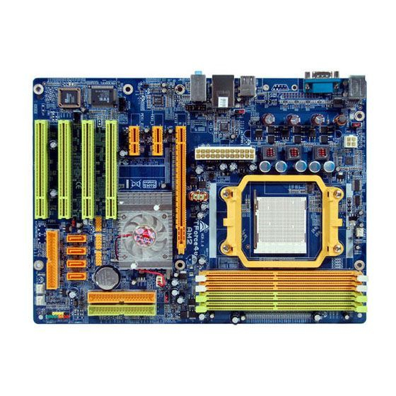
Page 6: Motherboard Layout
Motherboard Manual OTHERBOARD JKBMS1 JKBMSV1 JATXPWR2 JPRNT1 (optional) JATXPWR1 JUSB4 JUSBV1 JUSBLAN1 JAUDIO1 JAUDIO1 PCI-EX1_1 Codec PCI-EX1_2 JCDIN1 PCI1 Super I/O PCI2 JSPDIF_OUT1 BIOS PCI3 LED_D1 LED_D2 PCI4 Note: represents the 1 ■ AYOUT JCFAN1 PCI-EX16 nVIDIA nForce4 JUSB2 JUSB3... -
Page 7: Chapter 2: Hardware Installation
90-degree angle. Step 3: Look for the white triangle on socket, and the gold triangle on CPU should point towards this white triangle. The CPU will fit only in the correct orientation. TForce4 AM2 (CPU) ROCESSING... - Page 8 Motherboard Manual Step 4: Hold the CPU down firmly, and then close the lever toward direct B to complete the installation. Step 5: Put the CPU Fan on the CPU and buckle it. Connect the CPU FAN power cable to the JCFAN1. This completes the installation.
-
Page 9: Fan Headers
The JCFAN1、JSFAN1/JSFAN2 and JNFAN1 support 3-pin head connector. When connecting with wires onto connectors, please note that the red wire is the positive and should be connected to pin#2, and the black wire is Ground and should be connected to GND. TForce4 AM2 JCFAN1 Assignment Ground... -
Page 10: Installing System Memory
Motherboard Manual NSTALLING YSTEM A. Memory Modules Unlock a DIMM slot by pressing the retaining clips outward. Align a DIMM on the slot such that the notch on the DIMM matches the break on the Slot. Insert the DIMM vertically and firmly into the slot until the retaining chip snap back in place and the DIMM is properly seated. -
Page 11: Memory Capacity
256MB/512MB/1024MB DDR2B2 256MB/512MB/1024MB C. Dual Channel Memory installation To trigger the Dual Channel function of the motherboard, the memory module must meet the following requirements: Install memory module of the same density in pairs, shown in the following table. DDR2A1... -
Page 12: Connectors And Slots
IDE1/IDE2: Hard Disk Connectors The motherboard has a 32-bit Enhanced PCI IDE Controller that provides PIO Mode 0~4, Bus Master, and Ultra DMA 33/66/100/133 functionality. It has two HDD connectors IDE1 (primary) and IDE2 (secondary). - Page 13 PCI-EX1_1 PCI-EX1_2 PCI1~PCI4: Peripheral Component Interconnect Slots This motherboard is equipped with 4 standard PCI slots. PCI stands for Peripheral Component Interconnect, and it is a bus standard for expansion cards. This PCI slot is designated as 32 bits. TForce4 AM2...
-
Page 14: Jpanel1: Front Panel Header
Motherboard Manual CHAPTER 3: HEADERS & JUMPERS SETUP OW TO ETUP The illustration shows how to set up jumpers. When the jumper cap is placed on pins, the jumper is “close”, if not, that means the jumper is “open”. Pin opened... - Page 15 Assignment +3.3V -12V Ground PS_ON Ground Ground Ground Ground JATXPWR2: ATX Power Source Connector By connecting this connector, it will provide +12V to CPU power circuit. TForce4 AM2 Assignment +3.3V +3.3V Ground Ground Ground PW_OK Standby Voltage+5V +12V +12V +3.3V...
- Page 16 Motherboard Manual JKBMSV1: Power Source Selection Headers for Keyboard/Mouse Pin 1-2 Close: JKBMSV1: +5V for PS/2 keyboard and mouse。 Pin 2-3 Close: JKBMSV1: PS/2 keyboard and mouse are powered with +5V standby voltage. JUSB2/JUSB3/JUSB4: Headers for USB 2.0 Ports at Front Panel This header allows user to connect additional USB cable on the PC front panel, and also can be connected with internal USB devices, like USB card reader.
- Page 17 Pin 2-3 individually. JFAUDIO1: Front Panel Audio Header This header allows user to connect the front audio output cable with the PC front panel. It will disable the output on back panel audio connectors. TForce4 AM2 Pin 1-2 close JUSBV1 JUSBV2...
-
Page 18: Clear Cmos Procedures
Motherboard Manual JCDIN1: CD-ROM Audio-in Connector This connector allows user to connect the audio source from the variaty devices, like CD-ROM, DVD-ROM, PCI sound card, PCI TV turner card etc.. JCMOS1: Clear CMOS Header By placing the jumper on pin2-3, it allows user to restore the BIOS safe setting and the CMOS data, please carefully follow the procedures to avoid damaging the motherboard. - Page 19 JSATA1~JSATA4: Serial ATA Connectors The motherboard has a PCI to SATA Controller with 4 channels SATA interface, it satisfies the SATA 1.0 spec and with transfer rate of 1.5Gb/s. JSATA1 JSATA2 JSATA3 JSATA4 JPRNT1: Printer Port Connector This header allows you to connector printer on the PC.
-
Page 20: Onboard Led Indicators
Before setting memory voltage overclocking, please ensure that your DDR supports up to 2.3V. (Consulting your DDR supplier) On-Board LED Indicators There are 2 LED indicators on the motherboard to show system status. LED_D1 and LED_D2: These 2 LED indicate system power on diagnostics. - Page 21 PWRSW RSTSW (Optional) (Optional) PWRSW1: This is an on-board Power Switch button. RSTSW2: This is an on-board Reset button. JSPDIF_OUT1: Digital Audio-out Connector This connector allows user to connect the PCI bracket SPDIF output header. TForce4 AM2 Assignment SPDIF_OUT Ground...
-
Page 22: Chapter 4: Nvidia Raid Functions
Motherboard Manual CHAPTER 4: NVIDIA RAID FUNCTIONS PERATION YSTEM Supports Windows XP Home/Professional Edition, and Windows 2000 Professional. RRAYS NVRAID supports the following types of RAID arrays: RAID 0: RAID 0 defines a disk striping scheme that improves disk read and write times for many applications. - Page 23 Drawbacks: Requires 2 drives for the storage space of one drive. Performance is impaired during drive rebuilds. Fault Tolerance: Yes. Block 1 Block 2 Block 3 TForce4 AM2 Block 1 Block 2 Block 3...
- Page 24 Motherboard Manual RAID 0+1: RAID 0 drives can be mirrored using RAID 1 techniques. Resulting in a RAID 0+1 solution for improved performance plus resiliency. Features and Benefits Drives: Minimum 4, and maximum is 6 or 8, depending on the platform.
-
Page 25: Chapter 5: Overclock Quick Guide
5.1: OWER NTRODUCTION Biostar T-Power is a whole new utility that is designed for overclock users. Based on many precise tests, Biostar Engineering Team (BET) has developed this ultimate overclock engine to raise system performance. No matter whether under BIOS or Windows interface, T-Power is able to present the best system state according to users’... -
Page 26: T-Power Bios Feature
Motherboard Manual 5.2: T-P BIOS F OWER A. Overclocking Navigator Engine (O.N.E.): ONE provides two powerful overclocking engines: MOS and AOS for both Elite and Casual overclockers. Manual Overclock System (M.O.S.) MOS is designed for experienced overclock users. It allows users to customize personal overclock settings. - Page 27 Chipset Overclock Setting: Chipset Voltage Regulator: This function will increase chipset stability when overclocking. Choices: 1.550V, 1.600V, 1.650V, 1.700V. HT Frequency: We recommend users to set this item at “x4” when overclocking. Choices: x1, x2, x3, x4, x5, Auto. TForce4 AM2...
- Page 28 Motherboard Manual Automatic Overclock System (A.O.S.) For beginners in overclock field, BET had developed an easy, fast, and powerful feature to increase the system performance, named A.O.S. Based on many tests and experiments, A.O.S. provides 3 ideal overclock configurations that are able to raise the system performance in a single step.
- Page 29 Users are able to reload any saved CMOS setting for customizing system configurations. Moreover, users are able to save an ideal overclock setting during overclock operation. There are 50 sets of record addresses in total, and users are able to name the CMOS data according to personal preference. TForce4 AM2...
- Page 30 Motherboard Manual C. Memory Integration Test (M.I.T.): This function is under “Overclocking Navigator Engine” item. MIT allows users to test memory compatibilities, and no extra devices or software are needed. Step 1: The default setting under this item is “Disabled”; the condition parameter should be changed to “Enable”...
- Page 31 E. Integrated Flash Program (I.F.P.): IFP is a safe and quick way to upgrade BIOS. Step 1: Go to Biostar website (http://www.biostar.com.tw) to download the latest BIOS file. Then, save the file into a floppy disk. Step 2: Insert the floppy disk and reboot the system to get into CMOS screen.
-
Page 32: Smart Fan Function
Motherboard Manual F. Smart Fan Function: Smart Fan Function is under “PC Health Status”. This is a brilliant feature to control CPU Temperature vs. Fan speed. When enabling Smart Fan function, Fan speed is controlled automatically by CPU temperature. This function will protect CPU from overheat problem and maintain the system temperature at a safe level. - Page 33 S3: CPU temperature is 60℃, and PWM value is 3 PWM/℃. Increasing the value of slope PWM will raise the speed of CPU fan. As in above diagram, when the CPU temperature reaches 60℃, the CPU fan speed for 3 PWM/℃ is higher than 1 PWM/℃ (S1<S2<S3). TForce4 AM2...
-
Page 34: T-Power Windows Feature
Motherboard Manual OWER INDOWS A.Hardware Monitor: T-Power Hardware monitor allows users to monitor system voltage, temperature and fan speed accordingly. Additionally, a rescue action will be taken by the program automatically while the system faces an abnormal condition. The program will trigger an alarm or shut down the system when unpredictable errors occur. -
Page 35: Cpu Temperature
If any one of the fans speeds is lower than the set value, the status line will change into a red warning line, and the program will trigger an alarm system automatically. Also, the system tray icon TForce4 AM2 would change to... -
Page 36: Reference Data
Motherboard Manual CPU/Battery Voltage VCore This item displays the CPU voltage, represented by a light blue line. Users can set the upper and lower limit by adjusting CPU operating voltage. If CPU voltage is higher or lower than the set value, the status line will change into a red warning line, and a warning sound will alert you. - Page 37 4 sub-screens, users can tune the system performance to an optimal level. TForce4 AM2 Graphic 1 Clicking on “Biostar” will lead you to the Biostar Homepage. This column shows the CPU speed information. C. Click on this button and the utility will pop-up 4 sub-screens (Please refers to Graphic 3).
- Page 38 Motherboard Manual CPU Overclocking Settings: By adjusting for CPU overclocking. Memory Overclocking Settings: By adjusting Memory overclocking. A. Memory Clock Frequency B. Memory Voltage AGP/PCI-Express Overclocking Setting: By adjusting overclocking. And this function helps to increase VGA card performance. Range: 100MHz~150MHz.
- Page 39 TForce4 AM2 PCI Overclocking Setting: This diagram shows present PCI working status and helps to monitor PCI peripherals working status. This item cannot be adjusted.
- Page 40 Motherboard Manual C. Smart Fan Function When Smart Fan Function is activated, screens will pop-up to illustrate the fan speed information. CPU Temperature: Show current CPU temperature. CPU Fan speed: Show current CPU Fan speed. iii. System Fan speed: Show current system Fan speed.
- Page 41 Cursor Up or Down. vi. Program Tool Bar: About: Click on this button to get program-related information. Minimize: Click on this button to minimize the program to system tray Exit: Click on this button to exit this program. TForce4 AM2...
-
Page 42: Live Update
When Live Update program is activated, a screen will pop up to illustrate BIOS related information. Link to Internet: Click on this button will link to Biostar website and BIOS file will be downloaded. Update BIOS: Click on this button to run BIOS flashing process, and it’s easy and safe. -
Page 43: Chapter 6: Useful Help
You will see the following window after you insert the CD The setup guide will auto detect your motherboard and operating system. Note: If this window didn’t show up after you insert the Driver CD, please use file browser to locate and execute the file SETUP.EXE under your optical drive. -
Page 44: Award Bios Beep Code
BIOS contents are corrupted. In this Case, please follow the procedure below to restore the BIOS: 1. Make a bootable floppy disk. 2. Download the Flash Utility “AWDFLASH.exe” from the Biostar website: www.biostar.com.tw 3. Confirm motherboard model and download the respectively BIOS from Biostar website. -
Page 45: Cpu Overheated
If the system shutdown automatically after power on system for seconds, that means the CPU protection function has been activated. When the CPU is over heated, the motherboard will shutdown automatically to avoid a damage of the CPU, and the system may not power on again. -
Page 46: Troubleshooting
Motherboard Manual 6.4 T ROUBLESHOOTING Probable No power to the system at all Power light don’t illuminate, fan inside power supply does not turn Indicator light on keyboard does not turn on. System inoperative. Keyboard lights are on, power indicator lights are lit, and hard drive is spinning. - Page 47 TForce4 AM2...
-
Page 48: Appendencies: Spec In Other Language
Motherboard Manual APPENDENCIES: SPEC IN OTHER LANGUAGE ERMAN Sockel AM2 AMD Athlon 64 / Athlon 64 FX / Althlon 64X2/ Sempron Prozessoren Unterstützt HyperTransport mit einer Bandbreite von bis zu 1000 MHz nVIDIA nForce4 Chipsatz ITE 8712F Bietet die häufig verwendeten alten Super E/A Super E/A-Funktionen. - Page 49 TForce4 AM2 Spezifikationen CPU-Lüfterstromversorgungsanschluss (mit Smart Fan-Funktion) x3 System-Lüfter-Stromversorgungsanschluss x1 Zur Erkennung eines geöffneten Gehäuses x3 Jeder Anschluss unterstützt 2 Fronttafel-USB-Anschlüsse Biostar behält sich das Recht vor , ohne Ankündigung die Unterstützung für ein Betriebssystem hinzuzufügen oder zu entfernen.
-
Page 50: France
Motherboard Manual RANCE Socket AM2 Processeurs AMD Athlon 64 / Athlon 64 FX / Althlon 64X2 / Sempron Prend en charge Hyper Transport jusqu'à Bus frontal une bande passante de 1000 MHz nVIDIA nForce4 Chipset ITE 8712F Fournit la fonctionnalité de Super E/S Super E/S patrimoniales la plus utilisée. - Page 51 Alimentation électrique du ventilateur système Pour la fonction de détection d'intrus dans le châssis Chaque connecteur prend en charge 2 ports USB de panneau avant Biostar se réserve le droit d'ajouter ou de supprimer le support de SE avec ou sans préavis.
-
Page 52: Italian
Motherboard Manual TALIAN Socket AM2 Processori AMD Athlon 64 / Athlon 64 FX / Althlon 64X2 / Sempron Supporto di HyperTransport fino a 1000 MHz di larghezza di banda nVIDIA nForce4 Chipset ITE 8712F Fornisce le funzionalità legacy Super Super I/O I/O usate più... - Page 53 Supporto RAID 0 / 1 / 0+1 speciali Sistemi operativi Windows 2K / XP supportati TForce4 AM2 SPECIFICA Ciascun connettore supporta 2 porte USB pannello frontale Biostar si riserva il diritto di aggiungere o rimuovere il supporto di qualsiasi sistema operativo senza preavviso.
-
Page 54: Spanish
Motherboard Manual PANISH Conector AM2 Procesadores AMD Athlon 64 / Athlon 64 FX / Athlon 64X2 / Sempron Admite HyperTransport con un ancho de banda de hasta 1000 MHz Conjunto de nVIDIA nForce4 chips ITE 8712F Le ofrece las funcionalidades heredadas de Súper E/S... - Page 55 Fuente de alimentación de ventilador de sistema Función de detección de intrusos en el chasis Cada conector soporta 2 puertos USB frontales Biostar se reserva el derecho de añadir o retirar el soporte de cualquier SO con o sin aviso previo.
-
Page 56: Portuguese
Motherboard Manual ORTUGUESE Socket AM2 Processadores AMD Athlon 64 / Athlon 64 FX / Althlon 64X2 / Sempron Suporta a tecnologia HyperTransport com uma largura de banda até 1000 MHz nVIDIA nForce4 Chipset ITE 8712F Proporciona as funcionalidades mais Especificaçã... - Page 57 Fan) Alimentação da ventoinha do sistema Para detectar qualquer intrusão no chassis Cada conector suporta 2 portas USB no painel frontal A Biostar reserva-se o direito de adicionar ou remover suporte para qualquer sistema operativo com ou sem aviso prévio.
-
Page 58: Polish
Motherboard Manual OLISH Socket AM2 Procesor AMD Athlon 64 / Athlon 64 FX / Procesory Althlon 64X2 / Sempron Obsługa HyperTransport o szerokości pasma do 1000 MHz Chipset nVIDIA nForce4 Gniazda DDR2 DIMM x 4 Pamięć Każde gniazdo DIMM obsługuje moduły główna... - Page 59 Obsluga systemu Windows 2K / XP operacyjne TForce4 AM2 SPEC Zasilanie wentylatora systemowego Do funkcji wykrywania naruszenia obudowy Każde złącze obsługuje 2 porty USB na panelu przednim Biostar zastrzega sobie prawo dodawania lub odwoływania obsługi dowolnego systemu operacyjnego bez powiadomienia.
-
Page 60: Russian
Motherboard Manual RUSSIAN Гнездо AM2 (центральн Процессоры AMD Athlon 64 / Athlon 64 ый FX / Althlon 64X2 / Sempron процессор) Поддержка HyperTransport с пропускной способностью до 1000 МГц Набор nVIDIA nForce4 микросхем Слоты DDR2 DIMM x 4 Основная Каждый модуль DIMM поддерживает... - Page 61 процессора (с функцией интеллектуального вентилятора) Источник питания для вентилятора системы Для функции обнаружения злоумышленника шасси Каждый разъём поддерживает 2 USB-порта на лицевой панели Biostar сохраняет за собой право добавлять или удалять средства обеспечения для OS с или без предварительного уведомления.
-
Page 62: Arabic
Motherboard Manual ARABIC ﺗﻤﻜﻦ ﺗﻘﻨﻴﺔAMD 64 ﺏﺖ و إﺝﺮاء اﻟﻌﻤﻠﻴﺎت اﻟﺤﺎﺳﻮﺏﻴﺔ ﺏﺴﺮﻋﺔ ﺗﺪﻋﻢ ﺗﻘﻨﻴﺔHyper Transport وCool’n’Quiet وﺣﺪة ذاآﺮةDDR2 ﻡﺰدوﺝﺔ اﻟﻘ DDR2 ﻡﻴﺠﺎ ﺏﺎﻳﺖ008 / 766 / 335 / 004 ﺳﻌﺎت ﺮة ﻡﻦ ﻥﻮع ﺗﺪﻋﻢ اﻟﺬاآ ﻻ ﺗﺪﻋﻢ رﻗﺎﺋﻖ اﻟﺬاآﺮةDIMM اﻟﻤﺴﺠﻠﺔ وﺗﻠﻚ اﻟﺘﻲ ﻻ ﺗﺘﻮاﻓﻖ ﻡﻊECC "وﻇﻴﻔﺔSmart Guardian"... - Page 63 ﻳﺪﻋﻢ آﻞ ﻡﻨﻔﺬ ﻓﺘﺤﺘﻲUSBﺏﺎﻟﻠﻮﺣﺔ اﻷﻡﺎﻡﻴﺔ ﺗﺤﺘﻔﻆBiostar ﺏﺤﻘﻬﺎ ﻓﻲ إﺿﺎﻓﺔ أو إزاﻟﺔ اﻟﺪﻋﻢ ﻷي ﻥﻈﺎم ﺗﺸﻐﻴﻞ ﺏﺈﺥﻄﺎر أو ﺏﺪون إﺥﻄﺎر TForce4 AM2 اﻟﻤﻮاﺻﻔﺎت ﻋﺪد ﻡﻨﻔﺬ ﻋﺪد ﺏﻮس د ﻡﻨﻔﺬ ﺗﻮﺹﻴﻞ اﻟﻄﺎﻗﺔ ﻋﺪد دﺏﺎﺏﻴﺲ ﻡﻨﻔﺬ ﺗﻮﺹﻴﻞ اﻟﻄﺎﻗﺔ ﻋﺪد PS/2 ﻟﻮﺣﺔ ﻡﻔﺎﺗﻴﺢ ﻋﺪد...
-
Page 64: Japanese
Motherboard Manual JAPANESE Socket AM2 AMD Athlon 64 / Athlon 64 FX / Althlon 64X2 / Sempron プロセッサ 1000 MHz のバンド幅までハイパートランス ポートをサポートします チップセット nVIDIA nForce4 DDR2 DIMMスロット x 4 各DIMMは 256/512MB & 1GB DDR2をサポ メインメモリ ート 最大メモリ容量4GB ITE 8712F もっとも一般に使用されるレガシーSuper I/O Super I/O 機能を採用しています。... - Page 65 PS/2マウス シリアルポート 背面パネル LANポート USBポート オーディオジャック ボードサイズ 218 mm (幅) X 293 mm (高さ) NVIDIA nTunes 特殊機能 RAID 0 / 1 / 0+1 のサポート OSサポート Windows 2K / XP TForce4 AM2 仕様 デジタルオーディオアウト機能をサポートします CPUファン電源装置(スマートファン機能を搭載) システムファン電源装置 シャーシ侵入検出機能 各コネクタは2つのフロントパネルUSBポートをサポートし ます Biostarは事前のサポートなしにOSサポートを追加または削 除する権利を留保します。...
Need help?
Do you have a question about the TForce4 AM2 and is the answer not in the manual?
Questions and answers