Table of Contents
Advertisement
GeForce 6100-M7
FCC Information and Copyright
This equipment has been tested and found to comply with the limits of a Class
B digital device, pursuant to Part 15 of the FCC Rules. These limits are designed
to provide reasonable protection against harmful interference in a residential
installation. This equipment generates, uses and can radiate radio frequency
energy and, if not installed and used in accordance with the instructions, may
cause harmful interference to radio communications. There is no guarantee
that interference will not occur in a particular installation.
The vendor makes no representations or warranties with respect to the
contents here and specially disclaims any implied warranties of merchantability
or fitness for any purpose. Further the vendor reserves the right to revise this
publication and to make changes to the contents here without obligation to
notify any party beforehand.
Duplication of this publication, in part or in whole, is not allowed without first
obtaining the vendor's approval in writing.
The content of this user's manual is subject to be changed without notice and
we will not be responsible for any mistakes found in this user's manual. All the
brand and product names are trademarks of their respective companies.
i
Advertisement
Table of Contents

Subscribe to Our Youtube Channel
Related Manuals for Biostar GeForce 6100 M7


Summary of Contents for Biostar GeForce 6100 M7
- Page 1 GeForce 6100-M7 FCC Information and Copyright This equipment has been tested and found to comply with the limits of a Class B digital device, pursuant to Part 15 of the FCC Rules. These limits are designed to provide reasonable protection against harmful interference in a residential installation.
-
Page 2: Table Of Contents
Table of Contents Chapter 1: Introduction ... 1 Motherboard Features ... 1 Layout and Components... 4 Chapter 2: Hardware Installation ... 5 Installing Central Processing Unit (CPU) ... 5 FAN Headers ... 6 Installing System Memory ... 7 Connectors and Slots ... 8 Chapter 3: Headers &... -
Page 3: Chapter 1: Introduction
GeForce 6100-M7 CHAPTER 1: INTRODUCTION OTHERBOARD Supports Socket 754. Supports AMD Athlon 64 processor up to 3700+. Supports AMD Sempron processor. Supports HyperTransport Technology up to 1600MT/s. Chipset North Bridge: nVIDIA GeForce6100. South Bridge: nVIDIA nForce 410. Dimensions Micro ATX Form Factor: 21.86cm (L) x 24.4cm (W) Operating System Supporting Supports Windows 2000 and Windows XP. - Page 4 GeForce 6100-M7 System Memory Supports up to 2 DDR devices. Supports DDR-266/333/400. Maximum memory size is up to 2GB. (Following table is only for reference.) DIMM Socket Location DIMM1 128MB/256MB/512MB/1GB *1 DIMM2 128MB/256MB/512MB/1GB *1 Onboard AC’97 Sound Codec Chip: ALC655 Support 6 channels.
- Page 5 GeForce 6100-M7 Internal On-board I/O Connectors and Headers 1 front panel header supports front panel facilities. 1 CD-in connector supports 1 CD-ROM audio-in device. 1 front audio header supports front panel audio function. 1 S/PDIF-Out connector supports digital audio-out function. 1 chassis open header supports PC case-opened warning function.
-
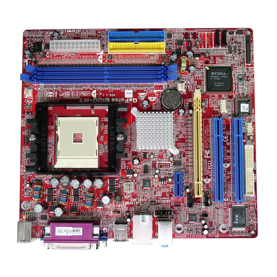
Page 6: Layout And Components
GeForce 6100-M7 AYOUT AND OMPONENTS JKBMS1 JUSBV1 JUSB1 JATXPWR2 JUSBLAN1 JFAUDIO1 JAUDIO1 PCI-EX1_1 JCDIN1 Codec PCI-EX16 JSPDIF_OUT1 PCI1 PCI2 Super I/O FDD1 Note: ■ represents the 1 JCFAN1 CPU1 GeForce 6100 BAT1 JSFAN1 nForce JUSB3 JUSBV2 BIOS JUSB2 pin. JATXPWR1 JSATA2 JSATA1 JCI1... -
Page 7: Chapter 2: Hardware Installation
GeForce 6100-M7 CHAPTER 2: HARDWARE INSTALLATION NSTALLING ENTRAL Step 1: Pull the lever toward direction A from the socket and then raise the lever up to a 90-degree angle. Step 2: Look for the black triangle on socket, and the white triangle on CPU should point forwards this black triangle. -
Page 8: Fan Headers
GeForce 6100-M7 FAN H EADERS These fan headers support cooling-fans built in the computer. The fan cable and connector may be different according to the fan manufacturer. Connect the fan cable to the connector while matching the black wire to pin#1. -
Page 9: Installing System Memory
GeForce 6100-M7 NSTALLING YSTEM Unlock a DIMM slot by pressing the retaining clips outward. Align a DIMM on the slot such that the notch on the DIMM matches the break on the Slot. Insert the DIMM vertically and firmly into the slot until the retaining chip snap back in place and the DIMM is properly seated. -
Page 10: Connectors And Slots
This connector supports the provided floppy drive ribbon cables. IDE1/IDE2: Hard Disk Connectors The motherboard has a 32-bit Enhanced PCI IDE Controller that provides PIO Mode 0~4, Bus Master, and Ultra DMA 33/66/100/133 functionality. It has two HDD connectors IDE1 (primary) and IDE2 (secondary). - Page 11 GeForce 6100-M7 PCI1~PCI2: Peripheral Component Interconnect Slots This motherboard is equipped with 2 standard PCI slots. PCI stands for Peripheral Component Interconnect, and it is a bus standard for expansion cards. This PCI slot is designated as 32 bits. PCI-EX16: PCI-Express x16 Slot PCI-Express 1.0a compliant.
-
Page 12: Chapter 3: Headers & Jumpers Setup
GeForce 6100-M7 CHAPTER 3: HEADERS & JUMPERS SETUP OW TO ETUP UMPERS The illustration shows how to set up jumpers. When the jumper cap is placed on pins, the jumper is “close”, if not, that means the jumper is “open”. Pin opened ETAIL ETTINGS... - Page 13 GeForce 6100-M7 JATXPWR1: ATX Power Source Connector This connector allows user to connect 24-pin power connector on the ATX power supply. JATXPWR2: ATX Power Source Connector By connecting this connector, it will provide +12V to CPU power circuit. Assignment +3.3V +3.3V Ground Ground...
- Page 14 GeForce 6100-M7 JUSB2/JUSB3: Headers for USB 2.0 Ports at Front Panel This header allows user to connect additional USB cable on the PC front panel, and also can be connected with internal USB devices, like USB card reader. JCDIN1: CD-ROM Audio-in Connector This connector allows user to connect the audio source from the variaty devices, like CD-ROM, DVD-ROM, PCI sound card, PCI TV turner card etc..
- Page 15 It will disable the output on back panel audio connectors. JSATA1~JSATA2: Serial ATA Connectors The motherboard has a PCI to SATA Controller with 2 channels SATA interface, it satisfies the SATA 2.0 spec and with transfer rate of 3GB/s.
-
Page 16: Jci1 Chassis Open Header
By placing the jumper on pin2-3, it allows user to restore the BIOS safe setting and the CMOS data, please carefully follow the procedures to avoid damaging the motherboard. ※ ※ ※ ※ Clear CMOS Procedures: Remove AC power line. -
Page 17: Front Panel Header
GeForce 6100-M7 JPANEL1: Front Panel Header This 24-pin connector includes Power-on, Reset, HDD LED, Power LED, Sleep button, speaker and IrDA Connection. It allows user to connect the PC case’s front panel switch functions. Assignment Function Speaker Connector Speaker HDD LED (+) Hard drive HDD LED (-) Ground... -
Page 18: Chapter 4: Useful Help
BIOS contents are corrupted. In this Case, please follow the procedure below to restore the BIOS: 1. Make a bootable floppy disk. 2. Download the Flash Utility “AWDFLASH.exe” from the Biostar website: www.biostar.com.tw 3. Confirm motherboard model and download the respectively BIOS from Biostar website. - Page 19 If the system shutdown automatically after power on system for seconds, that means the CPU protection function has been activated. When the CPU is over heated, the motherboard will shutdown automatically to avoid a damage of the CPU, and the system may not power on again.
-
Page 20: Troubleshooting
GeForce 6100-M7 ROUBLESHOOTING Problem No power to the system at all Power light don’t illuminate, fan inside power supply does not turn Indicator light on keyboard does not turn on. System inoperative. Keyboard lights are on, power indicator lights are lit, and hard drive is spinning. -
Page 21: Chapter 5: Warpspeeder
GeForce 6100-M7 WARPSPEEDER™ CHAPTER 5: NTRODUCTION [WarpSpeeder™], a new powerful control utility, features three user-friendly functions including Overclock Manager, Overvoltage Manager, and Hardware Monitor. With the Overclock Manager, users can easily adjust the frequency they prefer or they can get the best CPU performance with just one click. The Overvoltage Manager, on the other hand, helps to power up CPU core voltage and Memory voltage. -
Page 22: Installation
Tray Icon utility and [WarpSpeeder™] utility will be automatically and immediately launched after you click “Finish” button. Usage: The following figures are just only for reference, the screen printed in this user manual will change according to your motherboard on hand. -
Page 23: Warpspeeder™] Includes 1 Tray Icon And 5 Panels
GeForce 6100-M7 ™] PEEDER INCLUDES TRAY ICON AND PANELS 1. Tray Icon: Whenever the Tray Icon utility is launched, it will display a little tray icon on the right side of Windows Taskbar. This utility is responsible for conveniently invoking [WarpSpeeder™] Utility. - Page 24 GeForce 6100-M7 2. Main Panel If you click the tray icon, [WarpSpeeder™] utility will be invoked. Please refer to the following figure; the utility’s first window you will see is Main Panel. Main Panel contains features as follows: a. Display the CPU Speed, CPU external clock, Memory clock, AGP clock, and PCI clock information.
- Page 25 GeForce 6100-M7 3. Voltage Panel Click the Voltage button in Main Panel, the button will be highlighted and the Voltage Panel will slide out to up as the following figure. In this panel, you can decide to increase CPU core voltage and Memory voltage or not.
- Page 26 GeForce 6100-M7 4. Overclock Panel Click the Overclock button in Main Panel, the button will be highlighted and the Overclock Panel will slide out to left as the following figure. Overclock Panel contains the these features: a. “–3MHz button”, “-1MHz button”, “+1MHz button”, and “+3MHz button”: provide user the ability to do real-time overclock adjustment.
- Page 27 GeForce 6100-M7 “Auto-overclock button”: User can click this button and [WarpSpeeder™] will set the best and stable performance and frequency automatically. [WarpSpeeder™] utility will execute a series of testing until system fail. Then system will do fail-safe reboot by using Watchdog function. After reboot, the [WarpSpeeder™] utility will restore to the hardware default setting or load the verified best and stable frequency according to the Recovery Dialog’s setting.
- Page 28 GeForce 6100-M7 6. About Panel Click the “about” button in Main Panel, the button will be highlighted and the About Panel will slide out to up as the following figure. In this panel, you can get model name and detail information in hints of all the chipset that are related to overclocking.
- Page 29 GeForce 6100-M7 Note: Because the overclock, overvoltage, and hardware monitor features are controlled by several separate chipset, [WarpSpeeder™] divide these features to separate panels. If one chipset is not on board, the correlative button in Main panel will be disabled, but will not interfere other panels’...
Need help?
Do you have a question about the GeForce 6100 M7 and is the answer not in the manual?
Questions and answers