Sony PMW-F3L PMW-F3K Operating Instructions Manual
Solid-state memory camcorder
Hide thumbs
Also See for PMW-F3L PMW-F3K:
- Operating instructions manual (166 pages) ,
- Supplement manual (22 pages) ,
- Brochure & specs (10 pages)

Related Manuals for Sony PMW-F3L PMW-F3K


Summary of Contents for Sony PMW-F3L PMW-F3K
-
Page 1: Operating Instructions
4-276-626-11(1) Solid-State Memory Camcorder PMW-F3K PMW-F3L Operating Instructions Before operating the unit, please read this manual thoroughly and retain it for future reference. © 2011 Sony Corporation... - Page 2 apparatus has been exposed to rain or WARNING moisture, does not operate normally, or has To reduce the risk of fire or electric shock, been dropped. do not expose this apparatus to rain or moisture. IMPORTANT To avoid electrical shock, do not open the The nameplate is located on the bottom.
- Page 3 (controlled EMC environment, ex. TV studio). (-) estão no sentido indicado. As pilhas poderão vazar ou explodir se as The manufacturer of this product is Sony polaridades forem invertidas, expostas ao Corporation, 1-7-1 Konan, Minato-ku, Tokyo, fogo, desmontadas ou recarregadas.
-
Page 4: Table Of Contents
Table of Contents Overview Features ..................9 Using the Software ..............11 Reading the CD-ROM Manuals ..........12 Parts Identifications ..............13 Camcorder ..............13 IR Remote Commander (Supplied) ......18 Lenses (Supplied with the PMW-F3K) ......18 On-Screen Indications ............19 Indications in E-E Display/Recording Mode .... - Page 5 Recording Basic Operation Procedure ............ 36 Selecting the Video Format ............ 37 Selectable Formats ............37 Switching between HD and SD ........38 Changing the Format ............ 39 Switching the ND Filters ............39 Using the 5600K CC Filter ............. 40 Adjusting the White Balance ..........
- Page 6 Interval Recording ..............60 Preparatory Settings ............. 60 Performing Interval Recording ........60 Frame Recording ..............61 Preparatory Settings ............. 61 Performing Frame Recording ........62 Picture Cache Recording ............63 Preparatory Settings ............. 63 Performing Picture Cache Recording ......63 Slow &...
- Page 7 Copying Clips ............... 88 Deleting Clips ............... 89 Displaying the EXPAND CLIP Screen ......90 Displaying the SHOT MARK Screen (HD Mode Only) ..............91 Adding/Deleting Shot Marks (HD Mode Only) ... 92 Changing the Index Frame (HD Mode Only) ....92 Dividing a Clip (HD Mode Only) ........
- Page 8 Automatic Retrieval of a Lens File ......123 Connecting External Devices Connecting External Monitors and Recording Device ..124 Operating Clips With a Computer ........125 Connecting an External Device (i.LINK Connection) ..128 Recording the Camcorder Picture on an External Device ..............
-
Page 9: Overview
Overview Features Dual-Link output function The PMW-F3K/F3L is a highly compact and high-performance digital cinema camcorder that Signals of 1080/50P or 1080/59.94P fed from the uses SxS memory cards as its recording HD SDI A/B (Dual-Link) connectors can be medium. It employs a Super-35mm-equivalent recorded on an external device. - Page 10 RM-B750/B150 Remote Control Unit. function that intermittently records signals at pre- determined intervals. This is convenient for Sony, XDCAM, XDCAM EX, SxS, i.LINK, Exmor, shooting over long periods of time and also when CineAlta, and Remote Commander are trademarks of creating pictures with special effects of extremely Sony Corporation.
-
Page 11: Using The Software
HDV is a trademark of Sony Corporation and Victor Company of Japan, Limited. Using the Software Cooke Optics Limited HDMI, HDMI logo and High-Definition Multimedia Interface are trademarks or registered trademarks of HDMI Licensing, LLC in the United States and other countries. -
Page 12: Reading The Cd-Rom Manuals
URL mentioned in “Preparations” above. Note If you have lost or damaged the CD-ROM, you can purchase a new one to replace it. Contact your Sony service representative. Reading the CD-ROM Manuals... -
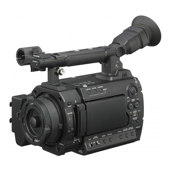
Page 13: Parts Identifications
Parts Identifications For functions and usage, see the pages shown in parentheses. Camcorder Upper operation block (page 16) 5 6 0 0 K C C S D I T E R L C D C A C B A T B R IG E A S C A N C... - Page 14 Operation block on the handle (page 16) H D M I O U L IN K (H D V /D V ) REC START/ STOP A U D R E M C H -1 IO IN O T E S P A M IC L IN E C H -2...
- Page 15 Side panel LENS INFO BRT DISP HISTOGRAM CACHE ASSIGN 5600K CC S&Q ND FILTER AUDIO CH-1 CH-2 LEVEL AUDIO CH-1 CH-2 SELECT AUTO MANUAL MONITOR VOLUME SHUTTER WHITE TC/U-BIT/ DISPLAY/ GAIN BALANCE ZEBRA PEAKING STATUS DURATION BATT INFO ASSIGN 5 PRST 9 10 11 ASSIGN (assignable) 1/2/3 buttons (page...
- Page 16 Operation block on the handle Rear panel Operation block HD SDI MENU SEL/SET CANCEL BATTERY RELEASE PICTURE PROFILE Protective cover (page 36) ASSIGN 6/7 (assignable 6 and 7) buttons (page 58) REC START/STOP (recording start/stop) button (page 36) SLOT SELECT ON OFF DC IN Upper operation block...
- Page 17 Connector block Bottom HD SDI MENU SEL/SET CANCEL SDI OUT BATTERY RELEASE PICTURE PROFILE VIDEO OUT TC IN TC OUT SLOT SELECT ON OFF GENLOCK IN DC IN Tripod receptacles Note 3 4 5 6 7 Check that the size of the hole matches the HD SDI A/B (Dual-Link) connectors screw of the tripod.
-
Page 18: Ir Remote Commander (Supplied)
IR Remote Commander (Supplied) Lenses (Supplied with the PMW- F3K) The buttons without remarks can be used in the same manner as the corresponding buttons on the camcorder. PUSH SET SHOTMARK ZOOM THUMBNAIL SUB CLIP PREV PLAY/PAUSE NEXT STOP > FREV FFWD REC PAUSE... -
Page 19: On-Screen Indications
On-Screen Indications Indications in E-E Display/Recording Mode Remarks When this unit is in E-E Display /Recording [M]: The indication of the items named with this mode, pressing the DISPLAY/BATT INFO button displays the statuses and settings of this suffix can be independently turned on/off unit on the LCD monitor/viewfinder screen. - Page 20 Zoom position indication [M] (page 48) Electric color compensation filter indication [M] (page 40) ND filter indication [M] (page 39) TLCS mode indication [M] (page 105) Backlight mode STD STD Standard mode Spotlight mode White balance mode and color temperature indications [M] (page 40) Picture profile indication [M] (page 67) Iris position indication [M] (page 48) Gain indication [M] (page 45)
-
Page 21: Preparations
If you connect an AC power source, it has a priority even if a battery pack is mounted. Battery pack For safety, use only the Sony battery pack and AC adaptor listed below: • BP-U60 Lithium-ion Battery Pack • AC-DN10 AC Adaptor... -
Page 22: Using Ac Power (Dc In Power)
charge level and usage time remaining are displayed on the LCD monitor/viewfinder screen. BATTERY I NFO 100% 120min STBY S&Q REC A: 25min Remaining Ti me : 20m i n B: 50min Icon Remaining 100% to 91% 90% to 71% 70% to 51% 50% to 31% 30% to 11%... -
Page 23: Turning Power On
For details, refer to the Operating Instructions of the AC-DN10. Setting the Area of Use and the Clock When recording or playback is in progress on power from the DC IN connector, the input voltage is displayed on the LCD monitor/ When you turn the camcorder on for the first time viewfinder screen. - Page 24 Turn the jog dial to select the desired For details on menu operations, see “Basic Menu Operations” on page 100. area of use. Notes Setting Area of use • If the clock setting is cleared because of NTSC Area NTSC area (for areas other exhaustion of the backup battery while no than Japan) operation power was being supplied (no battery...
-
Page 25: Adjusting The Lcd Monitor And Viewfinder
subject. The display direction of the textual information is converted to the readable direction. Adjusting the LCD Monitor and Viewfinder Adjusting the LCD Monitor 90° You can adjust the angle and the display 180° conditions of the LCD monitor for the best view in various shooting situations. -
Page 26: Adjusting The Viewfinder
Press the MENU button to set the camcorder to Menu mode and select (LCD/VF SET Eyepiece focusing knob menu) then “LCD” from the menu. LCD/VF SET Color Cont rast Peaking Br i ght ness Marker 00:00 Zebra Display On/O f f Set color, contrast and brightness of the LCD monitor with the corresponding LCD menu Adjusting the backlight... -
Page 27: Attaching A Lens
For other lenses usable with the PMW-F3K/F3L, ask lens in place. a Sony service representative. For information on handling lenses, refer to the While holding the lens, turn the lens operation guide of the lenses. -
Page 28: Using Lens Files
The lenses supplied with the PMW-F3K are Pull the lens forward to remove. aberration correction lenses. Note Contact a Sony service representative for information about other aberration correction When another lens is not immediately attached, lenses. attach the lens mount cap to its original position... -
Page 29: Attaching The Microphone
Cable clamp Attaching the Microphone Two channels (CH-1/CH-2) of audio can be recorded (Linear PCM recording) in synchronization with video recording. Using the Supplied Microphone Attach the microphone as follows: Loosen the screw of the microphone holder and open the cover. Connect the white plug of the supplied microphone to the CH-1 connector of the camcorder and the red plug to the CH-2... -
Page 30: Using External Inputs Or Optional Microphones
CH-1 to MIC+48V and that for CH-2 to MIC. Using the IR Remote Sony-made microphones which support both Commander stereo and monaural modes • Microphone supplied with this camcorder • ECM-680S Before use Before you use the supplied IR Remote... - Page 31 Note WARNING To avoid malfunctions, the remote control • Battery may explode if mistreated. function is automatically deactivated when the Do not recharge, disassemble, or dispose of in camcorder is turned off. Activate the function fire. each time when required after you turn the •...
-
Page 32: Handling Sxs Memory Cards
• SxS memory cards to be used with this standard. camcorder must be formatted using the format • SxS, SxS PRO and SxS-1 are trademarks of Sony function of this camcorder. If a card is formatted Corporation. using other device, it is regarded as of a •... -
Page 33: Inserting/Removing An Sxs Memory Card
Insert the SxS memory card into the Write-protect switch slot. M E N S E L /S C A N P IC T U R Note Do not operate the write-protect switch of an SxS memory card while it is set in the camcorder. Temporarily remove the card from the camcorder D C I before changing the switch setting. -
Page 34: Switching Between Sxs Memory Cards
Press the eject button again to remove Note on formatting the card. Any SxS memory card formatted with a device other than this camcorder cannot be used with the M E N S E L /S camcorder. C A N P IC T U R To execute formatting Using “Format Media”... -
Page 35: Restoring An Sxs Memory Card
The available time for recording with the current such a card, a warning message is displayed. video format (recording bit rate) is calculated Release the write protection or replace the card, according to the remaining space of each card and as per the instructions in the message. -
Page 36: Basic Operation Procedure
Recording Basic Operation Procedure Basic recording can be performed with the To stop recording, press the REC following procedures: START/STOP button again. (If you are using the IR Remote Commander, press Preparations the REC PAUSE button simultaneously with the unmarked button.) Recording stops and the camcorder enters Mount a fully charged battery pack. -
Page 37: Selecting The Video Format
See“Deleting Clips Collectively” on page 77. Selecting the Video To specify a clip to be deleted, use the thumbnail Format screen. See“Deleting Clips” on page 89. You can select various video formats for Clip (recording data) and clip name recording/playback using “System” of the When you stop recording, video, audio and OTHERS menu. -
Page 38: Switching Between Hd And Sd
With “PAL Area” selected Format Indication on this camcorder Format Indication on this HQ 1440 × 1080 HQ 1440/23.98P camcorder 23.98 Progressive 720 × 576 DVCAM50i SQ SP 1440 × 1080 SP 1440/59.94i 50 interlace, squeeze 59.94 interlace 720 × 576 DVCAM50i EC SP 1440 ×... -
Page 39: Changing The Format
For the menu items “Format” of “System” of the OTHERS menu and “SDI/HDMI/i.LINK I/O Switching the ND Filters Select” of the VIDEO SET menu the settings for HD mode and those for SD mode are independently stored in memory. When you switch between HD and SD, these items are ND filters are available for keeping the aperture automatically changed to the conditions... -
Page 40: Using The 5600K Cc Filter
Using the 5600K CC Adjusting the White Filter Balance When you press the 5600K CC button, the The white balance must be adjusted to suit to the indicator lights and the 5600K CC (electric color color temperature of the light source. compensation) filter is activated. -
Page 41: Executing Auto White Balance
To the B position of the WHITE BALANCE Note switch, ATW mode is assigned at the factory. The Auto white-balance adjustment cannot be setting can be changed with “White Switch <B>” executed in Preset mode. (page 105) of the CAMERA SET menu to select Memory B mode. -
Page 42: Adjusting The Black Balance
For details on menu operations, see “Basic Menu balance adjustment again. Operations” on page 100. If the error message continues to be displayed after several attempts, consult your Sony service Close the iris. representative. When using a lens on which the iris can be closed, such as the lens supplied with the PMW-F3K, close the iris. -
Page 43: Displaying The Markers And Zebra Patterns
Example: 95% Displaying the Markers 120min STBY TCG 00:00:00:00 and Zebra Patterns During recording, various markers and zebra patterns can be inserted into the image on the LCD monitor/viewfinder screen. This does not affect recording signals. When the aspect marker is on, the safety zone marker shows the effective area within the aspect marker. -
Page 44: Displaying The Zebra Patterns
Displaying the guide frame lines Turning the zebra-pattern indication on/ Set “Guide Frame” to “On” to insert the guide frame lines into the screen area. Pressing the ZEBRA button turns the zebra- pattern indication on/off. 120min STBY TCG 00:00:00:00 Displaying the Zebra Patterns A zebra pattern(s) can be inserted to the picture on the LCD monitor/viewfinder screen to check the appropriate luminance level. -
Page 45: Setting The Gain
L: 0 dB M: 6 dB Setting the Gain H: 12 dB These values can be changed in the range of –3 dB to +18 dB, using the CAMERA SET menu. To change You can set the gain of the video amplifier Press the MENU button to set the camcorder to according to the brightness of the subject. -
Page 46: Setting The Electronic Shutter
Note Setting the Electronic When Auto Shutter mode is On, the fixed shutter cannot be selected. Shutter The electronic shutter of the camcorder permits you to change the shutter speed (the accumulation time per recording frame). The electronic shutter can be adjusted automatically or manually as required. -
Page 47: Shooting In Slow Shutter Mode
Frame rate Shutter speed (sec.) Notes • Slow Shutter cannot be used when the video format is SP 1440/23.98P, the camcorder is in 1000 2000 Slow & Quick Motion mode, or “Auto Shutter” 29.97P is “On.” 1000 2000 • When a format of the interlace system is selected, the Slow Shutter On/Off setting Angle (standard angle) mode cannot be changed in the following conditions:... -
Page 48: Adjusting The Iris
Adjusting the Iris Adjusting the Zoom Adjust the iris opening using the iris ring of the When using a zoom lens, rotate the zoom ring of lens according to the brightness of the subject. the lens to adjust the zoom. For operations of the lens, refer to the operation For operations of the lens, refer to the operation guide of the lens. -
Page 49: Adjusting The Focus
The emphasis level and color of the contours can be set with “Peaking” (page 110) of the LCD/VF Adjusting the Focus SET menu. Rotate the focus ring of the lens for the best focus while observing the picture on the LCD monitor/ viewfinder screen. -
Page 50: Reducing Flickers
The recommended “Mode” settings are shown below. Reducing Flickers Flicker Environments Reduce/ Under lighting Under lighting Mode that may cause that does not flicker cause flicker To reduce flickers, try either of the following two Auto Recommended Acceptable methods: Acceptable Not recommended Not recommended Recommended... -
Page 51: Setting The Time Data
mode selected with the TC/UB SET menu is restored. Setting the Time Data Setting the Timecode Specify the timecode to be recorded with Time data, such as the timecodes, user bits, and “Timecode” and “TC Format” of the TC/UB SET the clock time, are recorded with pictures. -
Page 52: Setting The User Bits
for 1920/23.98P in, there may be a field that has dual Restrictions on the timecode timecodes on the display. With DF, the frame digits can be set as desired in the The timecode setting is restricted by the current range of 00 to 29. video format. -
Page 53: Recording Audio Signals
Display Contents Recording Audio Signals TCG **:**:**:** Tmecode CLK **:**:**:** Timecode (Clock mode) UBG ** ** ** ** User bits DUR **:**:** Duration from the beginning of recording Two channels (CH-1/CH-2) of audio can be recorded (Linear PCM recording) in synchronization with video recording. -
Page 54: Monitoring The Audio
Low: For music recording or recording in an Monitoring the Audio event where high sound pressure may be generated You can monitor the sounds being recorded with the headphones connected to the headphone To adjust the levels manually connector (stereo mini jack). Set the AUDIO SELECT switches CH-1 and CH- Headphone connector 2 to MANUAL and adjust the audio recording... -
Page 55: Outputting The Color Bars And Reference Tone
Notes Outputting the Color • When recording of the camera image is in progress, it cannot be switched to the color-bar Bars and Reference picture even if you press the BARS/CAM Tone button. (You can switch the color-bar picture to the camera picture.) •... -
Page 56: Recording Shot Marks
Recording Shot Marks Adding the OK Mark When you record shot marks for important scenes By adding the OK mark to a clip recorded in HD of a clip recorded in HD mode as subsidiary data, mode, you can prevent the clip from being deleted you can access the marked points easily on a Shot or divided inadvertently. -
Page 57: Rec Review
To add or delete the OK mark to or from clips before the last one Rec Review Use the Clip Operation menu on the thumbnail screen. See “Adding/Deleting the OK Mark to/from a Clip (HD Mode Only)” on page 88. You can review the last recorded clip on the screen (Rec Review). -
Page 58: Changing Functions Of The Assignable Buttons
If the clip was recorded in SD mode and segmented into multiple files because the file Changing Functions of size exceeded 2GB, only the last file is played. the Assignable Buttons • During Rec Review playback, the playback control buttons other than the STOP button are disabled. - Page 59 ASSIGN 2 button (BRT DISP) Function Contents Brightness-level indication on/off BRT Disp Brightness level indication on/off Histogram Histogram indication on/off ASSIGN 3 button (HISTOGRAM) Lens Info Depth-of-Field indication on/off Histogram indication on/off OK Mark add/delete OK Mark ASSIGN 4 and ASSIGN 5 buttons Valid in HD mode only Recording start/stop ASSIGN 6, ASSIGN 7, and ASSIGN 8 buttons...
-
Page 60: Interval Recording
Preparatory Settings Interval Recording Before starting Interval Recording, make the necessary settings on the CAMERA SET menu in advance. The Interval Recording (time-lapse recording) For details on menu operations, see “Basic Menu function is especially effective for shooting Operations” on page 100. objects that move very slowly. -
Page 61: Frame Recording
The flashing “Interval Rec” on the screen is now steadily lit. Frame Recording Notes • You cannot change the “Interval Time” and “Number of Frames” settings while Interval Recording is in progress. To change them, The Frame Recording function is especially pause recording. -
Page 62: Performing Frame Recording
Set “Setting” to “On.” • Some extra frames may be recorded if you stop recording or switch the card slot while The camcorder enters Frame Recording recording is paused in Frame Rec mode. mode. When the special recording mode indication Stopping Frame Recording on the screen is active, “Frame Rec”... -
Page 63: Picture Cache Recording
The Picture Cache Recording is enabled and the CACHE REC lamp lights. Picture Cache Recording CACHE REC lamp CACHE When the Picture Cache function is active, the camcorder stores the last few seconds of video captured in the built-in cache memory to permit you to start recording video on an SxS memory card from a point before you start recording. -
Page 64: Slow & Quick Motion Recording
Recording begins, and stored video in the cache memory is written first to the SxS memory card. Slow & Quick Motion The on-screen “ CACHE” indication changes Recording the color of to red. Stopping Picture Cache Recording When the camcorder is in HD mode and one of Press the REC START/STOP button on the the following video formats is selected (page 37), handle or the grip. -
Page 65: Preparatory Settings
Preparatory Settings Before starting Slow & Quick Motion recording, make the necessary settings with the CAMERA SET menu in advance. For details on menu operations, see “Basic Menu Operations” on page 100. Select “S&Q Motion” from the CAMERA SET menu. CAMERA SET CACHE Color Bar Type... -
Page 66: Freeze Mix: Image Alignment
Stopping recording Freeze Mix: Image Press the REC START/STOP button on the Alignment handle or the grip. Slow & Quick Motion recording stops. Using the Freeze Mix function, an image (still Note picture) of a clip recorded in HD mode can be When recording at a low-speed frame rate, it may temporarily superimposed on the current camera take time until recording stops after you press the... -
Page 67: Picture Profiles
• The Freeze Mix function cannot be used if the recording video format is SP 1440/23.98P. Picture Profiles • If the recorded picture and the current camera picture differ in video format, the Freeze Mix display cannot be achieved. • The Freeze Mix display cannot be obtained in You can customize the picture quality, depending Slow &... -
Page 68: Selecting A Picture Profile
Press the PICTURE PROFILE button. Example: The P.PROFILE menu is displayed. P.PROFILE Operating the jog dial, select “SEL” PP1: SceneA from the P. PROFILE menu then select PP2: SceneB the picture profile number (PP1 to PP3: SceneC PP4: SceneD PP10) to operate. PP5: SceneE PP6: SceneF P.PROFILE... -
Page 69: Resetting A Picture Profile
Resetting a Picture Profile P.PROFILE PP1: STANDARD Black You can reset a selected picture profile to the Black Gamma factory settings (standard status). Low Key Copy Select the picture profile you wish to PP Data S t o re Reset Reca l l reset as mentioned in “Selecting a Picture Profile using the P.PROFILE... - Page 70 When overwriting to the picture profile you specified in step 2 ends, the completion message is displayed for three seconds, and the loaded settings are immediately reflected. Note After you start loading, do not remove the SxS memory card until the completion message is displayed.
-
Page 71: Picture Profile Items
Picture Profile Items The values when “Off” is selected at “SEL” of the P.PROFILE menu are shown in bold face (example: Standard P. PROFILE SET Items Subitems and setting values Contents Profile Name Profile name Set the profile name in 8 characters at maximum. You can use upper- and lowercase alphabetics, Changing the picture profile numerics 0 to 9, - (hyphen), _ (underscore) and... - Page 72 P. PROFILE SET Items Subitems and setting values Contents White Offset White Set to “On” to shift the conversion value for auto On / Off white balance in Memory A or B mode and that for Setting the white balance auto tracing white in ATW mode to a lower color offset and the color temperature or a higher color temperature.
- Page 73 P. PROFILE SET Items Subitems and setting values Contents SD Detail Setting Set to “On” to apply the details to the video signal. On / Off Adjusting the details to be applied to the picture in SD Level Adjust the detail level. mode –99 to +99 (±0) Frequency...
- Page 74 P. PROFILE SET Items Subitems and setting values Contents Skin Tone Detail Setting Set to “On” to enable the detail level adjustment for On / Off specific color-phase areas. Adjusting the details to be The detail level is uniform over the entire picture applied to the areas of a with the Off setting.
- Page 75 P. PROFILE SET Items Subitems and setting values Contents Knee Setting Set to “On” to compress the high-luminance area of On / Off the picture. Adjusting the knee level Note Knee is fixed and cannot be changed in the following cases: •...
- Page 76 P. PROFILE SET Items Subitems and setting values Contents Black Gamma –99 to +99 (±0) Adjust the level of black gamma function that emphasizes only the dark areas of the picture to Adjusting the black gamma clear the tones or on the contrary de-emphasizes it level to reduce noise.
-
Page 77: Deleting Clips
For details on menu operations, see “Basic Menu Operations” on page 100. Deleting Clips Deleting Clips Collectively Using the Setup menu, you can delete the In E-E Display mode, the Last Clip DEL function recorded clips collectively from the SxS memory for deleting the last recorded clip and the All card in the selected card slot. -
Page 78: Playback
Playback Thumbnail Screens To return to the camera image When you press the THUMBNAIL button, the clips recorded on the SxS memory card are Press the STOP button to exit the thumbnail displayed as thumbnails on the screen. (If no clips screen, returning to the E-E picture (or external are recorded on the card, a no-clip message is input picture). -
Page 79: Configuration Of The Thumbnail Screen
Configuration of the Thumbnail Screen HD mode The icon of the current SxS memory card is highlighted, shading the nonselected one. (If the card is write-protected, a lock icon is displayed to the left.) Current clip No./ Total number of clips 120min 0011 / 0300 Cursor... - Page 80 SD mode The icon of the current SxS memory card is highlighted, shading the nonselected one. (If the card is write-protected, a lock icon is displayed to the left.) Current clip No./ Total number of clips 120min 0011 / 0300 Cursor (yellow) 01/JAN 10 : 53...
-
Page 81: Changing The Type Of Thumbnail Screen
Switching the SxS memory cards Changing the Type of Thumbnail Screen When two memory cards are loaded, press the SLOT SELECT button to switch memory cards. The type of thumbnail screen can be changed by Note pressing the THUMBNAIL button repeatedly. You cannot switch memory cards during In HD mode playback. -
Page 82: Playing Back Clips
The clips after the selected clips are played back Playing Back Clips in sequence. When playback of the last clip ends, the camcorder enters PAUSE (still picture) mode at the last frame of the last clip. For playback operations, use the following Press the THUMBNAIL button to return to the playback control buttons. -
Page 83: Monitoring Audio
Clip no./total number of clips on the With the headphones connected to the headphone memory card jack, the built-in speaker is turned off. Press the MONITOR VOLUME buttons to adjust Audio levels the sound volume. The audio levels in recording are displayed. The level bar is displayed during adjustment. -
Page 84: Adding Shot Marks During Playback (Hd Mode)
• When you press the button in normal or fast- forward playback, the top of the next clip is cued up then playback begins. • When you press the button in fast-reverse playback or in Pause mode, the top of the next clip is cued up, then the still picture is displayed. -
Page 85: Clip Operations
Clip Operations In Thumbnail Screen mode, you can operate the The corresponding Clip Operation menu pops up clips or confirm and change the subsidiary data on the screens as shown below. for clips using the Clip Operation menus. Clip Operation Menus Thumbnail screen (page 86) EXPAND CLIP screen (page 91) CANCEL... -
Page 86: Basic Operations Of The Clip Operation Menus
Item Function Basic Operations of the Clip SHOT To display thumbnails only of the Operation Menus frames with shot mark 2 recorded MARK2 (page 91) EXPAND CLIP To display the EXPAND CLIP Displaying a Clip Operation menu screen (page 90) for the clip Press the jog dial. -
Page 87: Displaying The Detailed Information Of A Clip
Displaying the Detailed Information of a Clip When you select “DISP CLIP INFO” from a Clip Operation menu, the CLIP INFO screen appears. HD Mode 120min CLI P I NFO 0011 / 0300 JPAN0011 ( 1 ) 01 / JAN / 2011 10 : 53 HQ 1920 / 23 .9 8 P S&Q Mot i on 29 / 24f p s TCR 00 : 05 : 00 : 02... -
Page 88: Adding/Deleting The Ok Mark To/From A Clip (Hd Mode Only)
For a clip recorded in S&Q Motion mode, Copying Clips [recording frame rate/playback frame rate] fps is displayed to the right. You can copy clips on an SxS memory card to Timecode of the displayed frame another SxS memory card. Timecode at the recording starting point Each clip is copied with the same name to the destination SxS memory card. -
Page 89: Deleting Clips
To copy, select “Execute” then press the Copying is canceled, and the OTHERS menu screen is restored. jog dial. Copying begins. When copying is completed The completion message is displayed. When the An execution message and an in-progress bar are OTHERS menu screen is restored, press the displayed during copying. -
Page 90: Displaying The Expand Clip Screen
Press the MENU button when the Select “EXPAND CLIP” from the Clip thumbnail screen of the clips to be Operation menu. deleted is displayed. The EXPAND CLIP screen appears for the clip that you selected on the thumbnail Select “All Clips DEL” from “Clip” of screen. -
Page 91: Displaying The Shot Mark Screen (Hd Mode Only)
Item Function EXPAND CLIP screen in SD mode SHOT MARK1 To delete shot mark 1 from the In SD mode, the thumbnail images of the first selected frame (page 92) frames of segment files are displayed for a clip SHOT MARK2 To delete shot mark 2 from the segmented because its file size exceeded 2GB on selected frame (page 92) -
Page 92: Adding/Deleting Shot Marks (Hd Mode Only)
The items other than the following are the same as Deleting a shot mark those on the EXPAND CLIP screen: You can delete shot marks on the EXPAND CLIP Timecode indication screen (page 90) or on the SHOT MARK screen The timecode of the frame at the cursor on the (page 91). -
Page 93: Dividing A Clip (Hd Mode Only)
Dividing a Clip (HD Mode Only) In HD mode, you can divide a clip into two different clips at the frame you select on the EXPAND CLIP screen (page 90) or the SHOT MARK screen (page 91). Select the frame at which the clip is to be divided on the EXPAND CLIP screen or the SHOT MARK screen then press the jog dial. -
Page 94: Status Displays
Status Displays Showing the Status Screens This camcorder provides status screens of five Switching the status screens kinds, permitting you to check the various settings and statuses of this unit. Operating the jog dial switches the screens in The status screens can also be displayed on an sequence. -
Page 95: Camera Status Screen
Skin Tone Detail: Skin-tone detail status The current status (On or Off) of “Setting” of CAMERA Status Screen “Skin Tone Detail” of the P.PROFILE menu is displayed. Picture Profile: Picture Profile selection status The selected Picture Profile number and name are The settings and statuses related to image displayed. -
Page 96: Audio Status Screen
Speaker: Speaker output The output audio channel(s) for the built-in AUDIO Status Screen speaker is(are) displayed. As the speaker is monaural, the outputs are CH-1+CH-2 or CH- 3+CH-4 even in stereo mode. With nonstereo settings, the “Monitor CH” Information regarding audio signals is displayed. setting of the AUDIO SET menu is valid as-is. -
Page 97: Video Status Screen
Display Contents VIDEO Status Screen SD HDMI P & HDV To output SD HDMI Progressive signals from the HDMI OUT connector and HDV streams from the i.LINK(HDV/DV) connector The information regarding video signals is SD HDMI i & HDV To output SD HDMI interlace displayed. -
Page 98: Button/Remote Status Screen
BUTTON/REMOTE Status BATTERY/MEDIA Status Screen Screen The functions assigned to the assignable buttons The information on the battery pack and SxS and the status of the IR Remote Commander are memory cards is displayed. displayed. BATTERY/ MED I A 5 / 5 Ba t t er y Charge Count 55 BUTTON / REMOTE... -
Page 99: Menu Configuration And Detailed Settings
Menu Configuration and Detailed Settings Overview of the Setup Menus This camcorder permits you to make various Setup Menu Layers settings for recording and playback with Setup menus on the LCD monitor/viewfinder screen. The Setup menus can also be displayed on an MENU external monitor. -
Page 100: Basic Menu Operations
Basic Menu Operations LENS FILE Information Operation Setting OTHERS All Reset This section covers basic operations for setting Camera Data the Setup menu items. Time Zone Clock Set Menu controls Language Assign Button Tally CANCEL button Hours Meter Jog dial IR Remote MENU button Battery Alarm... - Page 101 Example: When the cursor is located at CAMERA SET (CAMERA SET menu icon) Au t o Bl a ck Ba l . Menu icon Gain Setup Shu t t e r Slow Shut t e r 00:00 CAMERA SET Color Bar Type Mul t i F l i c ker Reduce Au t o Bl a ck Ba l .
- Page 102 temporarily disappears, and a confirmation Example message is displayed. Following the instructions CAMERA SET of message, specify whether to execute or cancel. Au t o Bl a ck Ba l . Entering a character string Gain Setup Shu t t e r When you select an item for which a character Slow Shut t e r 00:00...
-
Page 103: Setup Menu List
Setup Menu List The functions and available settings of menus are listed below. The default settings set at the factory are shown in bold face (example: Speed Note The items and setting values that cannot be selected at the time depending on the version of the camcorder, the input or output statuses and the setting status of other menu items, are shaded. - Page 104 CAMERA SET Menu items Subitems and setting values Contents Flicker Reduce Mode Set the operation of the Flicker-Reduction function. Auto / On / Off On: To always activate it Setting Flicker Auto: To automatically activate it when flicker is detected. Compensation Off: To not activate it Frequency...
- Page 105 CAMERA SET Menu items Subitems and setting values Contents Rec Review 3 sec / 10 sec / Clip Set the time to play the last recorded clip using the Rec- Review function. Setting the 3 sec: Last 3 seconds playback time for 10 sec: Last 10 seconds Rec-Review Clip: Entire duration of the clip...
-
Page 106: Audio Set Menu
CAMERA SET Menu items Subitems and setting values Contents Horizontal Inv. On / Off Set to “On” to horizontally invert the image. Setting the image inversion function Lens IF Type C / Type A / Off Select the appropriate lens interface in advance before attaching a lens. - Page 107 AUDIO SET Menu items Subitems and setting values Contents Audio Output Monitor CH Select the audio channel(s) to be fed to the headphones and CH-1/CH-2 (CH-3/CH-4) the built-in speaker. Setting for audio CH-1+CH-2 (CH-3+CH-4) CH-1/CH-2 (CH-3/CH-4): Stereo outputs CH-1 (CH-3) CH-1+CH-2 (CH-3+CH-4): Mix CH-2 (CH-4) CH-1 (CH-3): CH-1 (CH-3) only...
-
Page 108: Video Set Menu
VIDEO SET Menu VIDEO SET Menu items Setting values Contents Input Source Camera / i.LINK Select video and audio signal for the input source. Camera: Camera image Select i.LINK: HDV/DVCAM input via the i.LINK(HDV/DV) Setting the input connector source Note DVCAM input is for display only and cannot be recorded. -
Page 109: Lcd/Vf Set Menu
VIDEO SET Menu items Setting values Contents Video Out On / Off Set whether to add the same menus and status indications as those on the LCD monitor/viewfinder screen to the output Display signal from the VIDEO OUT connector. Setting the character Note information for the... - Page 110 LCD/VF SET Menu items Subitems and setting values Contents Backlight Select the brightness of the viewfinder backlight. High / Low Setting the viewfinder Mode Select the display mode of the viewfinder in E-E Display/ Color / B&W Recording mode. Color: Color mode B&W: Monochrome mode Contrast Adjust the contrast of pictures on the viewfinder screen.
- Page 111 LCD/VF SET Menu items Subitems and setting values Contents Display On/Off Video Level Warnings Turn the warning indication to be displayed when the picture On / Off is too bright or too dark on/off. Selecting the items to be displayed on Brightness Display Turn the numeric indication to show the picture brightness on/ the LCD monitor/...
-
Page 112: Tc/Ub Set Menu
TC/UB SET Menu TC/UB SET Menu items Subitems and setting values Contents Timecode Mode Set the timecode mode. Preset / Regen / Clock Preset: To start the timecode from the specified value Setting the Regen (regeneration): To continue the timecode from that of timecode the previous clip Clock: To use the current clock time as the timecode... -
Page 113: Lens File Menu
LENS FILE Menu LENS FILE Menu items Subitems and setting values Contents Information Lens Name The model name of the lens is displayed. Displaying the Manufacturer The manufacturer of the lens is displayed. information for the Serial Number The serial number of the lens is displayed. attached lens Version The version of the lens is displayed. - Page 114 LENS FILE Menu items Subitems and setting values Contents Setting Reset Setting Select “Execute” to clear the lens compensation data to the Execute/Cancel factory-set values. Performing adjustments for a Flare R Set an R flare level in the lens file. lens file –99 to +99 (±0) Flare G...
-
Page 115: Others Menu
OTHERS Menu OTHERS Menu items Subitems and setting values Contents All Reset Execute/Cancel Select “Execute” to reset the camcorder to the factory status. Resetting to the factory status Camera Data Store Select “Execute” to store the setting values in an SxS memory Execute/Cancel card. - Page 116 OTHERS Menu items Subitems and setting values Contents Assign Button <1> to <8> Assign a function to the ASSIGN button of the corresponding Off / Marker / Last Clip DEL / number. Assigning ATW / ATW Hold / Rec Review Marker: For turning the markers on/off functions to the / Rec / Picture Cache / Freeze...
- Page 117 OTHERS Menu items Subitems and setting values Contents Battery INFO Type The type (product name) is displayed. Showing MFG Date The date of manufacture is displayed. information Charge Count The accumulated number of times of charge/discharge is regarding the displayed. battery pack Capacity The estimated total capacity of full charge is displayed.
- Page 118 OTHERS Menu items Subitems and setting values Contents System Country Select the area of use and setup ON/OFF. NTSC Area / NTSC(J) Area / NTSC Area: Setup ON PAL Area NTSC(J) Area: Setup OFF PAL Area: Setup OFF HD/SD Switch between HD mode and SD mode for recording/ HD / SD playback.
- Page 119 OTHERS Menu items Subitems and setting values Contents Clip Title Prefix Call the Character Set screen to set the title part (4 to 46 nnn_ (nnn=least three digits of characters) of the clip names. Setting for clip the serial number) Configuration of the Character Set screen name or deletion (Max.
- Page 120 OTHERS Menu items Subitems and setting values Contents Version Up Execute / Cancel Use when updating of the camcorder is required. Select “Execute” to begin. Updating this unit Note This item cannot be selected when no SxS memory card has been loaded.
-
Page 121: Storing/Retrieving The Setting Data
Storing/Retrieving the Setting Data Setup File You can store all the menu settings (including Notes picture profiles) as a setup file on an SxS memory • If a setup file already exists on the memory card card. you specified in Step , a message to confirm By retrieving the stored setup file, the proper whether to overwrite the file is displayed. -
Page 122: Lens Files
viewfinder screen. If the icon of the other slot is displayed, press the SLOT SELECT button to Lens Files switch. Adjust the white balance. Press the MENU button to set the This camcorder can save the setting data used to camcorder to Menu mode and select the compensate for lens characteristics, such as flare, LENS FILE menu with... -
Page 123: Retrieving Lens Files
Select the file number under which you To use the Lens Auto Recall function, set “Auto Recall” under “Operation” of the LENS FILE wish to save the data then press the jog menu to one of the following: dial. On (Lens Name): Load the lens file that A confirmation message appears. -
Page 124: Connecting External Devices
Connecting External Devices Connecting External Monitors and Recording Device To display the menus and status information on To display recording/playback pictures on an the connected monitor external monitor, select the output signal and use an appropriate cable for the monitor to be Set “SDI/HDMI Out Display”... -
Page 125: Operating Clips With A Computer
External Device (i.LINK Connection)” on page For information on installation of the driver, refer to 128. the ReadMe on the supplied CD-ROM. For support information for the driver, visit the following URL: http://www.sony.net/SxS-Support/ to the ExpressCard slot SxS memory card Computer with SxS... - Page 126 Connecting with a USB cable Connect USB Now? Execute When you connect the camcorder or the SBAC- Cancel US10 SxS Memory Card USB Reader/Writer (optional) using the supplied USB cable, the memory card in the slot is acknowledged as an Note extended drive by the computer.
- Page 127 Store the clips to be edited on the HDD of your Removing an SxS memory card computer in advance, using the dedicated application software (supplied). Windows Some editing software may not operate properly. Click on the icon of “Safely Remove Be sure to confirm before use that it conforms to Hardware”...
-
Page 128: Connecting An External Device (I.link Connection)
camcorder is output as an HDV or DVCAM stream via the i.LINK(HDV/DV) connector. It Connecting an External can be recorded on a connected HDV or DVCAM Device (i.LINK recorder in synchronization with your recording start/stop operation on this camcorder. Connection) Perform the preparatory settings of the camcorder. -
Page 129: Nonlinear Editing
device before it enters synchronization even if Note “Trigger Mode” is set to “Both.” DVCAM streams cannot be recorded. • While you can record shot marks on the memory card during recording, they are not Set the external signal to a format that added to the pictures recorded on the external can be recorded on the camcorder. -
Page 130: About I.link
IEEE 1394 proposed by Sony, is a trademark supported by many companies worldwide. IEEE 1394 is an international standard defined by IEEE, the Institute of Electrical and Electronics Engineers, Inc. -
Page 131: External Synchronization
PAL Area External Synchronization Video format Valid reference signal HQ 1920/50i 1080/50i 576/50i HQ 1920/25P HQ 1440/50i HQ 1440/25P When multiple units of the PMW-F3K/F3L are SP 1440/50i used in the same shooting location, recording can HQ 1280/50P 1080/50i be made in synchronization with a specific 720/50P HQ 1280/25P reference signal, and the timecode can be... - Page 132 To release the external timecode synchronization Change the “Timecode” setting of the TC/UB SET menu or turn off the camcorder. External synchronization is also released when you start recording in a special recording mode (Slow & Quick Motion, Frame Rec, or Interval Rec).
-
Page 133: Appendixes
In such a case, stop using it and contact your dealer or a Sony service representative. Do not cover the unit while operating Putting a cloth, for example, over the unit can cause excessive internal heat build-up. - Page 134 Aliasing • In direct sunlight or close to heaters for extended periods When fine patterns, stripes, or lines are shot, they may appear jagged or flicker. To prevent electromagnetic interference from portable communications devices Flicker The use of portable telephones and other If recording is made under lighting produced by communications devices near this unit can result discharge tubes, such as fluorescent, sodium, or...
-
Page 135: Backup Battery
Notes on data compatibility with other Backup Battery XDCAM EX-series products • When you use other PMW-series products to play materials recorded on the PMW-F3K/F3L, any media in which clips of formats not This camcorder uses a backup battery to retain supported by those products have been recorded various setting data. - Page 136 Open the cover of the backup battery holder on the bottom by loosening the screw, and remove the battery. 0 2 5 C R 2 Insert a new backup battery (CR2032) with the + symbol on the battery facing outside. 0 2 5 C R 2 Attach the cover in the original position.
-
Page 137: Troubleshooting
Troubleshooting Operating Power Symptoms Cause Remedy The camcorder does not No battery pack is mounted and no Mount a battery pack (page 21) or connect an AC power on when you set power is supplied to the DC IN power using the AC-DN10 (page 22) . the power switch to ON. -
Page 138: External Devices
External Devices Symptoms Cause Remedy The equipment connected “Input Source Select” of the VIDEO Set it to “i.LINK.” to the camcorder via an SET menu is set to “Camera.” i.LINK connection does It sometimes takes time for the Wait for about 15 seconds. If the connected not react as expected, for connected equipment to recognize equipment still does not react, do the following:... -
Page 139: Error/Warning Indications
Turn off the power and check that the connected devices, cables, and media are in proper condition. If the error persists when you reapply power, consult Sony service personnel. (If power cannot be turned off by setting the power switch to OFF, remove both the battery pack and the DC IN source.) - Page 140 Warning indication Buzzer Tally Cause and measures on LCD/viewfinder lamps Backup Battery End The remaining power of the backup battery is insufficient. Please Change. Replace the battery with a new one. A partitioned memory card or one that contains recorded clips Unknown Media(A) exceeding the number permitted with this camcorder is loaded.
- Page 141 Warning indication Buzzer Tally Cause and measures on LCD/viewfinder lamps Not Enough Capacity There is not enough capacity for dividing a clip. Cannot Divide Media Reached The memory card comes to the end of its service life. Make a Rewriting Limit backup copy and replace the card with another one as soon as possible.
-
Page 142: Mpeg-2 Video Patent Portfolio License
MPEG-2 Video Patent Specifications Portfolio License ANY USE OF THIS PRODUCT OTHER THAN General CONSUMER PERSONAL USE IN ANY MANNER THAT COMPLIES WITH THE Power requirements MPEG-2 STANDARD FOR ENCODING DC 12 V (11.0 V to 17.0 V) VIDEO INFORMATION FOR PACKAGED MEDIA IS EXPRESSLY PROHIBITED Power consumption WITHOUT A LICENSE UNDER... -
Page 143: Camera Block
With one SBS-64G1A Audio Block SP or DVCAM mode: Approx. 280 min. HQ mode: Approx. 200 min. Sampling frequency Note 48 kHz The actual recording/playback time may Quantization differ slightly from the values shown 16 bits here, depending on usage conditions, Headroom memory characteristics, etc. -
Page 144: Inputs/Outputs
USB connector Inputs/Outputs Mini-B/USB2.0 Hi-Speed (1) Option connector Input connectors USB Type A (1) AUDIO IN CH1/CH2 connectors SPARE connector XLR 3-pin (2), female 10-pin round connector (1) LINE: +4 dBu MIC: –20 dBu to –65 dBu (3-dB steps) Lenses (Supplied with the PMW- (Reference level: 0 dBu=0.775 Vrms) F3K) GENLOCK IN connector... -
Page 145: Supplied Accessories
• Always make a test recording, and verify that it • Always verify that the unit is operating properly was recorded successfully. before use. SONY WILL NOT BE LIABLE SONY WILL NOT BE LIABLE FOR FOR DAMAGES OF ANY KIND... -
Page 146: Index
Index Backlight backlight (LCD) backlight (VF) backup battery BARS/CAM button Numerics Battery Alarm 23.98P Output Battery INFO 5600K CC button BATTERY INFO display 5600K CC filter Battery Pack BATTERY RELEASE button BATTERY/MEDIA Status AC Adaptor BC-U1 Battery Charger Access lamps Black accessory shoe Black Gamma... - Page 147 59, 66 Freeze Mix Date/Time DC IN Power gain delete a clip Gain Setting DELETE CLIP 45, 103 Gain Setup delete shot marks GAIN switch Deleting Clips Gamma Genlock diopter compensation GENLOCK IN connector DISP CLIP INFO Guide Frame Display On/Off 19, 22 DISPLAY/BATT INFO button divide a clip...
- Page 148 LCD B.LIGHT switch PICTURE PROFILE button LCD BRIGHT buttons Picture Profiles LCD monitor PLAY/PAUSE button LCD/VF SET Menu Post for the shoulder strap LENS FILE Menu Power switch Lens Files PP Data 27, 106 Lens IF PREV button LENS INFO Profile Name Lens Info Low Key SAT...
- Page 149 Skin Tone Detail 33, 81 SLOT SELECT button Warning Indications Slow & Quick Motion White 46, 47, 103 Slow Shutter WHITE BALANCE Speed mode white balance Spotlight WHITE BALANCE switch STATUS button White Switch 105 status screens write protection STOP button Store SxS Device Driver Software 44, 110...
Need help?
Do you have a question about the PMW-F3L PMW-F3K and is the answer not in the manual?
Questions and answers