Advertisement
Quick Links
Owner's Manual
®
!6.5 HP
ELECTRIC START
42" MOWER
HYDROSTATIO (AUTOMATmC)
LAWN TRACTO
Modet No.
917,271120
• Safety
,, Assembmy
o Operation
,, Maintenance
,, Repair
Parts
.4;
CAUTION:
Read and follow alJ
Safety RuJes and hstructions
before operating
this equip-
menL
For at_swers to yoL_r questions
about this product, Call:
1°800°659°59t
7
Sears Craftsmatl
He_p Line
5 am - 5 prn, Mon ,,Sat
Sears, Roebuck
and Coo, Hoffman Estates,
IL 60179
Advertisement

Related Manuals for Craftsman 917.271120


Summary of Contents for Craftsman 917.271120
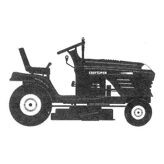
- Page 1 Owner's Manual ® !6.5 HP ELECTRIC START 42" MOWER HYDROSTATIO (AUTOMATmC) LAWN TRACTO Modet No. 917,271120 • Safety ,, Assembmy o Operation ,, Maintenance ,, Repair Parts CAUTION: For at_swers to yoL_r questions about this product, Call: Read and follow alJ 1°800°659°59t Safety RuJes and hstructions Sears Craftsmatl...
-
Page 2: Table Of Contents
LIMITED TWO YEAR WARRANTY ON CRAFTSMAN RIDING EQUIPMENT For two (2) years from the date of purchase, if this Craftsman Riding Equipment is main- tained, lubricated and tuned up according to the instructions in the owner's manual, Sears will repair or replace, free of charge, any parts found to be defective in material or workmanship. - Page 3 Turn offblades w hen notmowing. • Do nottry to stabilize the machine by . Stop engine b efore removing grass putting your foot on the ground. catcher orunclogging chute. Do not use grass catcher on steep Mow only indaylight orgood artificial slopes.
- Page 4 before restarting. manufacturer's recommended parts, Never make adjustments or repairs with when necessary. the engine running. Mower blades are sharp and can cut. Grass catcher components are subject Wrap the blade(s) or wear gloves, and to wear, damage, and deterioration, use extra caution when servicing them.
-
Page 5: Safety Rules
In the state of California the above is CONGRATULATIONS on your purchase required by law (Section 4442 of the of a Craftsman Tractor. It has been California Public Resources Code). Other designed,engineeredand manufactured states may have similar laws. Federal to give you the best possibledependability laws apply on federal lands. - Page 6 PARTS BAG CONTENTS SHOWN FULL S_ZE (1) Large Flat Washer (!) Hex BoJt 3/8-16 x 1 © (t) Lockwasher (1) Hex Bolt 5/16_18 5/16qBx 1-1/4 (I) Locknut (t) Shoulder Bott 5/16-18 (t) Washer 17/32 x 1-3/t6 x 12 Gauge (1) Knob Hex Bolts t/4-20 ×...
- Page 7 PARTS BAG CONTENTS SHOWN FULL S|ZE (2) Screws (2) Lock #t0 x 5/8 Washers #10 (2) Weld Nuts i---iI 3/t 6 (2_i_'taSlh6r_au ge_ Parts Bag contents not shown full size Parts packet separately in carton _Shoulder (2) Washers 3/8 x 7/8 x I4 Ga. Bolts Seat (2) Centertock...
-
Page 8: Assembly
Your new tractor has been assembled at the factory with exception of those parts left unassembled for shipping purposes. To ensure safe and proper operation of your tracto all parts and hardware you assemble must be tightened securely. Use the correct tools as necessary to insure proper tightness. -
Page 9: Product Specifications
iNSTALL SEAT HOW TO SET UP YOUR TRACTOR Adjust seat before tightening adjustment CONNECT BATTERY knob. _,CAUTION: Do not short battery termi- * Remove cardboard packing on seat pan. nals by allowing a wrench or any other Place seat on seat pan and assemble object to contact both terminals at the shoulder bolt. - Page 10 CHECK BRAKE SYSTEM Hook Points Weld Nut From After you learn how to operate your trac- Down The Top tor, check to see that the brake is properly Lock adjusted. See "TO ADJUST BRAKE" in Wetd Washer the Service and Adjustments section of this manual INSTALL MULCHER PLATE...
- Page 11 v' CHECKLIST ASSEMBLE GAUGE WHEELS TO MOWER DECK PLEASE REVIEW THE FOLLOWING The gauge wheels are designed to keep CHECKLIST: the mower deck in proper position when All assembly instructions have been operating mower, Be sure they are proper- completed. ly adjusted to ensure optimum mower per- V' No remaining loose parts in carton.
- Page 12 These symbols may appear onyour t ractor or in literature suppled with the product. Learn and understand their meaning. E::3A BATTERY CAUTION OR REVERSE FORWARD FAST SLOW WARNING MGHTS ON OVER TEMP OIL PRESSURE ENGINE ON ENG{NE OFF LIGHT PARKING BRAKE MOWER HEIGHT UNLOCKED MOWER...
- Page 13 KNOW YOUR TRACTOR READ THIS OWNER'S MANUAL AND SAFETY RULES BEFORE OPERATING YOUR TRACTOR Compare the illustrations with your tractor to familiarize yourself with the locations of various controls and adjustments. Save this manual for future reference. Light Switch Position Attachment ignition Clutch Lever...
- Page 14 eyes, which can result in severe eye damage. Always wear safety glasses The operation of any tractor can result in foreign objects thrown into the or eye shields whime operating your tractor or performing any adjustments repairs. We recommend a wide vision safety mask over the spectacles, or standard safety glasses.
- Page 15 soilconditions, height ofgrass a nd types clutch/brake pedal quickly to brake posto ofgrass b eing mowed, tion and engage parking brake. Theaverage lawn should b ecutto - Move motion control lever to neutral (N) approximately 2-1/2inches d uring the position. cool s eason a ndtoover 3 inches d uring iMPORTANT: The motion control lever hotmonths.
- Page 16 withSummer weight oit. * Sit on seat in operating position, Check e ngine o ilwith tractor on level depress clutch!brake pedal and set parking brake. ground. * Place motion control lever in neutral (N) Unthread and remove oil fill cap/dip- stick;...
- Page 17 feet) o r mately five (5) feet, slowly move motion in cold temperatures (below 32 F) control lever to reverse position. After the carburetor fuel mixture may need to be the tractor moves approximately five (5) adjusted for best engine performance. feet return the motion control lever to See "TO ADJUST CARBURETOR"...
- Page 18 ..E..and give best p erformance oftheat- For best results, adjust the mower cut- tachment being used. ting he!ght so that the mower cuts off only the top one-third of the grass MULCHING MOWING TiPS blades i For extremely heavy mulching, iMPORTANT: For best performance, keep reduce your width of cut on each pass mower housing free of built-up grass and...
- Page 19 CUSTOMER RESPONSiBILITiES a - # eqUip_3_ With oil _ilter, change oil every 50 bouts. 4 - _ep_ac_ b_ad_s mo_ts- often when mow_ _r_sandy _oil. GENERAL RECOMMENDATIONS The warranty on this tractor does not cover items that have been subjected to operator abuse or negligence.
- Page 20 TO SHARPEN BLADE TRACTOR NOTE: We do not recommend sharpenin. Always observe safety rules when per- blade, but if you do, be sure the blade is forming any maintenance. balanced. BRAKE OPERATION Care should be taken to keep the blade If tractor requires more than six (6) feet balanced.
- Page 21 Rinse t hebattery w ithplain water and Check the crankcase oil level before start- dry. ing the engine and after each eight (8) Clean terminals andbattery c able ends hours of operation. Tighten oil fill cap/dip- with wire brush until bright. stick securely each time you check the oil level.
- Page 22 CLEAN AIR INTAKE/COOLING AREAS o Remove oil filter and wipe off filter To insure proper cooiing, make sure the adapter. grass screen, cooling fins, and other , Apply a thin coating of new engine oil to the rubber gasket on replacement oil fit- external surfaces of the engine are kept clean at all times.
- Page 23 ° Keep finished surfaces and wheels free Clamp of all gasoline, oil, etc. , Protect painted surfaces with automo- tive type wax. We do not recommend using a garden __--- Fuel Filter hose to clean your tractor unless the elec- trical system, muffler, air filter and carbure- CLEANING tor are covered to keep water out.
- Page 24 TO LEVEL MOWER HOUSING , Before making any necessary adjust- ments, check thatboth front links are Adjust the mower while tractoris parked equal in length. Both links should be on levelground or driveway. Make sure approximately 10-3/8". tires are pmpedy inflated(See "PROD- •...
- Page 25 • Make sure belt is in all pulley grooves BELT INSTALLATION - and inside all belt guides. • Install new belt in reverse order of . install mower in reverse order of removal. removal instructions. Idler Mandrel Pulleys Pulley Mandrel Pulley TO REPLACE MOTION DRIVE BELT TO ADJUST BRAKE...
- Page 26 TO ADJUST MOTION CONTROL LEVER TO REMOVE WHEEL FOR REPAIRS The motion control lever has been preset ° Block up axle securely. o Remove axle cover, retaining ring and at the factory and adjustment should not washers to allow wheel removal (rear be necessary.
- Page 27 ° Connect theother e nd of the BLACK INTERLOCKS AND RELAYS cable to good CHASSIS GROUND, Looseor damaged wiringmay causeyour away from fuel tank and battery. tractorto run poorly,stop running, o r pre- TO REMOVE CABLES, REVERSE vent itfrom starting. ORDER - - Check wiring.See electrical w iringdia- •...
- Page 28 ENGINE which allows some adjustment within the limits allowed by the cap. Do not attempt TO ADJUST THROTTLE CONTROL. to remove the limiter cap. The iimiter cap CABLE cannot be removed without breaking the The throttle control has been preset at the adjusting needle.
- Page 29 Also, experience indicates that alcohol Immediately prepare your tractor for stor- blended fuels (called gasohol or using age at the end of the season or if the trac- tor will not be used for 30 days or more. ethanol or methanol) can attract moisture which leads to separation and formation of ,_CAUTION: Never store the tractor with...
-
Page 30: Service And Adjustments
TROUBLESHOOTING CHART CORRECTION -'C-AUSE Fill fuel tank. t¢ill not start _ Out of fuel. See "TO START ENGINE" in ,, Engine not "CHOKED" prop- Operation section. erly. = Wait several minutes before = Engine flooded. attempting to start. , Replace spark plug. Bad spark plug. -
Page 31: Troubleshooting
TROUBLESHOOTING CHART PROBLEM CAUSE CORRECTION i Lossof power(cont'd) trash under mower. o Clean underside of mower hous- + Dirtyair filter. ing. + Low o]tlevel/dirtyoil. - CJean/replace air filter. + Faulty spark plug. + Check oil level/change oil. . Clean and regap or change °... - Page 32 TROgBLESHOOTtNG CHART CORRECTION PROBLE_ CAUSE Poor grass discharge Low/uneven tire air pressure. Level mower deck. (cont'd) Check tires for proper air pres- ® Worn, bent or ]oose blade, sure. , Replace/sharpen blade. Tighten blade bolt. * Buildup of grass, leaves and trash under mower.
- Page 33 TRACTOR - MODEL NU_,/tBEFt917.271120 SCHEMATIC t_kACK BATTERY SOLENOID -------_)0 FUSE 30 AMP. STARTER AMMETER (OPTIONAL) IGNITION SWITCH 2S VOkT,_AC _ _0t:_ _V'M (R_GUkATQ_ DII_GONNECTED) NOTE YOUR TRACTOR IS EQUIPPED WITH A SPECIAL ALTERNATOR SYSTEM. THE LIGHTS ARE NOT CONNECTED TO THE BATTERY, BUT HAVE THEIR HEADLIGHTS OWN ELECTRICAL SOURCE.
- Page 34 TRACTOR - - MODEL NUMBER 917,271120 ELECTRICAL...
- Page 35 TRACTOR - - MODEL NUMBER 917,271120 ELECTRICAL PART DESCRIPTION 163465 Batter,/12 Vott 28 Amp 74760412 Bolt, Hex Head 1/4-20 unc x 3/4 Washer STD551025 STD551125 Washer STD541025 156417 Case, Battery Mech Hinge 161343 Switch, interlock N Opn/N Opn STD551125 Washer, Lock 73350400 NUt, Hex, Jam 1/4-20 UNC...
- Page 36 TRACTOR - - MODEL NUMBER 917.271120 CHASSIS AND ENCLOSURES...
- Page 37 TRACTORi- - MODEL NUMBER 917.271120 CHASSIS AND ENCLOSURES PART DESCRIPTION t 60392 Chassis Assembly Drawbar 140356 1 Screw, Thd. RoE 3/8-t6 x 3/4 t74906t_: Washer t3/32 x 3/4 x 16 Gauge 1913121_ 155272 Bumper Hood/Dash Dash 1619t7X013 STD533710 Boit, Carriage 3/8-16 x t 155927 Panel, Dash, L.H.
- Page 38 GROUND DRIVE TRACTOR.. MODEL NUMBER 9!7;271120 ' • ' :':<'":...
- Page 39 TRACTOR - - MODEL NUMBER 917,271120 GROUND DRIVE PART PART DESCRIPTION DESCRIPTION 150071 Transaxte Assembly Washer 13/32 x tol/4 x 12 142431 Spring, Return, Brake 19132012 Gauge 143995 Pulley, Transaxle Strap Torque Rh Hydro 18/20" 154792 Rod Shift Hydro LT 156347 76020416 Pin Cotter...
- Page 40 TRACTOR - - MODEL NUMBER 917.271120 STEERING ASSEMBLY...
- Page 41 TRACTOR _- MODEL NUMBER 917,271120 STEERING ASSEMBLY PART DESCRiPTiON 139768 Steering Wheet 154427 Axle Assembly STMP Dropped STL 156483 Spindle Assembly, L.H, 157473 Spindle AssembhJ, R.H, 6266H Bearing, Race, Thrust, Hardened 121748X Washer 25/32 x 1_5/8 x 16 Gauge t 9272016 Washer 27/32 x t-114 x 16 Gauge 12000029...
- Page 42 "TRACTOR "= MODEL NUMBER 917.271120 ENGINE 4/{_ _"_...
- Page 43 TRACTOR - - MODEL NUMBER 917.271120 ENGINE PART DESCRIPTION 162156 Control, Throttle/Choke 17720410 Screw, Hex Head, Thread Cutting 1/4-20 x 5/8 ..Engine, (See Breakdown) Kohler Modet No:CV16-43513 t 59420 Muffler 13280328 Nipple, Pipe 3/8 NPT x 3-1/2 13200300 Elbow, Standard 90°, 3/8-t8 NPT STD551237 Washer t59880...
- Page 44 TRACTOR -- MODEL NUMBER 917.271120 SEAT ASSEMBLY PART PART DESCRIPTION DESCRiPTiON 140123 Seat 121246X Bracket, Switch Mounting 140551 Bracket, PNot, Sea! 121248)( Bushing, Snap STD523710 Bolt 72050412 Bolt, Carriage t/4-20 x t-1/2 19131610 Washer 13/32 × 1 × 10 Gauge 134300 Spacer, Split .28 x .88 145006...
- Page 45 Decal Dash Pnl Kohfer t63205 163263 Decal, Lift Handle 163203 Decal, Deck Mower E.Z 138311 Pad Footrest LH STLT 163204 Decal, Fender, Craftsman 154515 Pad Footrest RH STLT i56439 Decal, Fender Danger 154516 142341 Decal, Drawbar Cntd Mvt Hyd 163488...
- Page 46 TRACTOR -- MODEL NUMBER 917o271120 LiFT ASSEMBLY 25 24...
- Page 47 TRACTOR -- MODEL NUMBER 917.271120 LiFT ASSEMBLY PART DESCRiPTiON 159460 Lift Lever InnerWire Assembly 159471 ShaftAssembly, Lift 105767X Pin, Groove 12000002 E-Ring 19211621 Washer 21/32 x 1 ×21 Gauge 120183)( Bearing, Nyl_ t2563tX Grip, Handle, Fluted t22365X Button, Plunger, Red 139865 Link, Lift, L,H, 139866...
- Page 48 TRACTOR - - MODEL NUMBER 917.271120 MOWER DECK >21...
- Page 49 TRACTOR - MODEL NUMBER 917,271120 MOWER DECK PART PART DESCRIPTIOI'4 DESCRIPTION 144393 122052X Spacer, Retainer Mower Housing STD533107 140086 Spring, Torsion Brakes Bolt 138017 141043 Guard, TUV idler Bracket Assembly, Sway Bar, Front 1621 t3 Knob Custom Oval 138440 Bracket Assembly, Sway Bar 144200 V-Belt STD624008...
- Page 50 TRACTOR -- MODEL NUMBER 917.271120 HYDRO GEAR TRANSAXLE - - MODEL NUMBER 205-038 5£...
- Page 51 TRACTOR - - MODEL NUMBER 9!7,271120 HYDRO GEAR TRANSAXLE - - MODEL NUMBER 205-038 PART PART DESCRIPTION DESCRIPTION 142930 Hot=sing, Lower 142884 Washer 7/16 x 7/8 x .060 142931 Assembly, Upper Housing 150829 Differential Assembly 142932 Seat, Lip 142991 Washer 3/4 x !.5 x .t3 142928 Ring, Wire Retaining...
- Page 52 TRACTOR - - MODEL NUMBER 917.271120 KOHLER ENGINE-MODEL NUMBER CV16S, TYPE NUMBER PS-435t3...
- Page 53 TRACTOR - - MODEL NUMBER 917.271120 KOHLER ENGINE-MODEL NUMBER CV16S, TYPE NUMBER PS-43513 CRANKCASE CYLINDER HEADiVALVFJBREATHER KEYPART KEYPART NO.NO, DESCRIPTION NO.NO. DESCRiPTiON 12-351-02 Lifter, valve (2) t2-032-03 Seal, crankshaft t2-755-63 Kit, cylinder head (includes 3- Block, cylinder (Use Shor_ Block 12 522 18) 12"445-02 Strap, Iifting t2-411-01...
- Page 54 TRACTOR - - MODEL NUMBER 917.271120 KOHLER ENGINE-MODEL NUMBER CV16S, TYPE NUMBSR PS-43513 BLOWER HOUSING AND BAFFLES...
- Page 55 TRACTOR - - MODEL NUMBER 917.271120 KOHLER ENGINE-MODEL NUMBER CV16S, TYPE NUMBER PS-43513 IGNITION/ELECTRICAL BLOWER HOUSING & BAFFLES KEYPART KEYPART NO.NO. DESCRIPTION NO.NO. DESCRIPTION 12-.086-t4 Screw, he×. flange MIOx1.Sx46 " M`05450t0 Screw, hex. flange MSx0.8×10 12-468-03 Washer, plain 3/8 24-468-10 24-t62-03 Washer, plain I/4 Screen, grass...
- Page 56 TRACTOR - - MODEL NUMBER 9!7,27t120 KOHLER ENGINE-MODEL NUMBER CV16S, TYPE NUMBER PS-43513 STARTING SYSTE_ ENGINE CONTROLS 4 f-,,Q _ _t0 °-! 19--...
- Page 57 TRACTOR o - MODEL NUMBER 917o27!120 KOHLER ENGNNE-MODSL NUMBER CV16S_ TYPE NUMBER PS-43513 STARTING SYSTEM ENGINE CONTROLS KEYPART KEYPART DESCBIPTION NO,NO, DESCRiPTiON NO.NO, M_0839070 Screw, hex. flange M8x1.25x70 12-079-07 Unkage, choke 2,5-098-05 Starter assembFy (Includes 3*8) t2-237`01 Ciamp, cabfe t2-755_54 Kit, drive end M`0664020 Screw, tobed socket M6xt.Ox20...
- Page 59 SUGGESTED GUIDE FOR SiGHTiNG SLOPES FOR SAFE OPERATION ONLY RIDE UP AND DOWN HILL, NOT ACROSS HILL SIGHT AND HOLD THIS LEVEL WITH SKY LINE OR TREE. 15 ° MAX. greater than 15°), never across the face. Make turns gradu- Operate your Tractor up and down the face of slopes (not agy to prevent tipping...
- Page 60 For the repair or replacement parts you need delivered directly to your home Call 7 am - 7 pm, 7 days a week 1-800-356oPART (1..800-366-7278) Para ordenar piezas con entrega a domiciiio - 1-800_659-7084 For in-house major brand repair service Call 24 hours a day, 7 days a week 1oSO0=4=REPAIR (1-800-473W274)
Need help?
Do you have a question about the 917.271120 and is the answer not in the manual?
Questions and answers