Table of Contents
Advertisement
Quick Links
Operator's
Manual
II:RRFTSMRN I
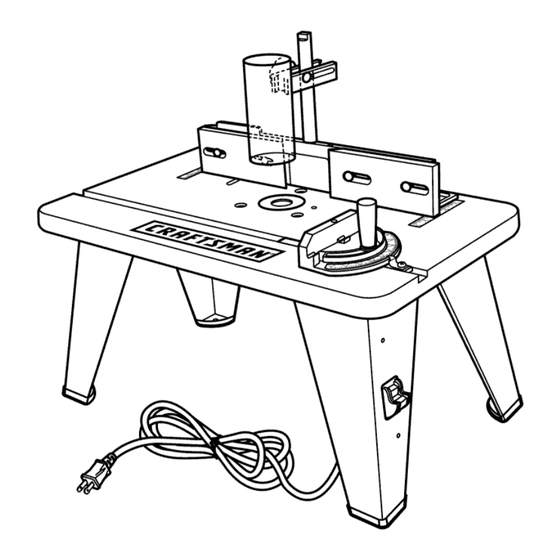
ROUTER
TABLE
Double Insulated
Model No.
315.265030
_h
WARNING:
To reduce the risk of injury, the
user must read and understand the operator's
manual before using this product.
Customer
Help Line: t-800-932-3188
Sears, Roebuck
and Co., 3333 Beverly Rd., Hoffman
Estates, IL 60179 USA
Visit the Craftsman web page: www.sears.com/craftsman
983000-479
Save this manual
for future
reference
7-04
Advertisement
Table of Contents

Related Manuals for Craftsman 315.265030


Summary of Contents for Craftsman 315.265030
- Page 1 Customer Help Line: t-800-932-3188 Sears, Roebuck and Co., 3333 Beverly Rd., Hoffman Estates, IL 60179 USA Visit the Craftsman web page: www.sears.com/craftsman 983000-479 Save this manual for future reference 7-04...
- Page 2 Parts Ordering/Service ..............................FULL ONE YEAR WARRANTY ON CRAFTSMAN TOOL If this CRAFTSMAN tool fails to give complete satisfaction within one year from the date of purchase, RETURN IT TO THE NEAREST SEARS STORE OR SEARS SERVICE CENTER IN THE UNITED STATES, and Sears will repair it, free of charge.
- Page 3 ALWAYS WEAR SAFETY GLASSES WITH SIDE WARNING: Read and understand all instruc- tions. Failure to follow all instructions listed below, SHIELDS. Everyday eyeglasses have only impact- may result in electric shock, fire and/or serious resistant lenses; they are NOT safety glasses. personal injury.
- Page 4 • DON'TABUSE CORD. N ever c arrytool bythecordor • KEEP HANDS AWAY FROM CUTTING AREA. Do not yankitto disconnect fromreceptacle. Keep cordfrom reach underneath the table or in the cutting path with heat,oil,andsharpedges. your hands or fingers at any time while the tool is •...
-
Page 5: Symbols
Someof the following symbols maybeusedonthis tool. Please studythemandlearntheirmeaning. P roper interpretation ofthesesymbols willallowyouto operate thetool betterandsafer. SYMBOL NAME DESIG NATION/EXPLANATION Volts Voltage Amperes Current Hertz Frequency (cycles per second) Watt Power Minutes Time "_ Alternating Current Type of current Direct Current Type or a characteristic of current No Load Speed... -
Page 6: Symbols
Thefollowing signal w ordsandmeanings a reintended to explain the levels ofriskassociated withthisproduct. SYMBOL SIGNAL MEANING Indicates an imminently hazardous situation, which, if not avoided, will DANGER: result in death or serious injury. Indicates a potentially hazardous situation, which, if not avoided, could WARNING: result in death or serious injury. -
Page 7: Electrical
DOUBLE INSULATION EXTENSION CORDS Double insulation is a concept in safety in electric power When using a power tool at a considerable distance from tools, which eliminates the need for the usual three-wire a power source, be sure to use an extension cord that has grounded power cord. - Page 8 PRODUCT SPECIFICATIONS Miter Slot ........3/8 in x 3/4 in. x 24 in. Table Dimensions .... 14 in. x 24 in. (35.6 cm x 61 cm) Maximum Cutter Diameter ....1-15/16 in. (4.9 cm) (0.9 cm x 1.9 cm x 61 cm) Fence Width ........
-
Page 9: Features
KNOW YOUR ROUTER TABLE SWITCH See Figure 1. This product is equipped with a power switch that has a built-in locking feature. This feature is intended to prevent Before attempting to use this product, familiarize yourself unauthorized and possible hazardous use by children and with all operating features and safety rules. -
Page 10: Assembly
UNPACKING PACKING LIST This product requires assembly. 1. Router table top (1) • Carefully remove the tool and any accessories from the 2. Miter gauge knob (1) box. Make sure that all items listed in the packing list 3. Washer (1) are included. - Page 11 WARNING:Donotconnect t o powersupply until SWITCH assembly i s complete. Failure to complycouldresult ASSEMBLY inaccidental starting andpossible serious injury. ASSEMBLING THE ROUTER TABLE SWITCH When you remove the parts and hardware from the pack- ing materials, check all items with the packing list and CUTOUT drawing.
- Page 12 TO ATTACH THE FENCE See Figure 6. • Position the fence on the tame as shown in figure 6. BLACK.CUTTER KNOB GUARD • Align the ho(es on the bottom of the fence with the LOOSEN channe(s on the router tame. •...
- Page 13 ATTACHING THE REAR SAFETY GUARD TO MOUNTING THE TABLE TO A WORK THE ROUTER SURFACE See Figure 9. See Figures 11 and 12. • Align the holes in the rear safety guard with the holes in • Place the router table right side up on a sturdy work the router.
-
Page 14: Operation
PERFORMING A ROUTING OPERATION WARNING" Do not allow familiarity with your tool to make you careless. Remember that a careless See Figure 13, fraction of a second is sufficient to inflict serious • Read the entire 175100 Router Operator's Manual. injury. - Page 15 INSERTING/REMOVING CUTTERS INSERTING THROAT PLATES See Figure 14. See Figure 15. • Unplug the router and the router table. The throat plate provides a stable surface around the cutter and prevents objects from falling through the throat and damaging the spindle. WARNING: To prevent damage to the spindle or spindle lock, always allow the motor to come to a...
- Page 16 ADJUSTING DEPTH OF CUT POSITIONING THE FENCE See Figure 16. See Figure 17. We recommend that cuts be made at a depth not exceed- The fence enables you to support and guide the work- ing 1/8 in. (3.2 mm) and that several passes be made to piece.
- Page 17 ADJUSTING THE MITER GAUGE INSERTING THE STARTING See Figure 20. See Figure 19. The purpose of the starting pin is to act as a guide with • Loosen the miter gauge knob. piloted bits. • Rotate the miter gauge to the desired angle. Place the starting pin on the router table and use it as a •...
-
Page 18: Maintenance
When servicing, use only identical spackling compounds, or plaster are subject to accel- Craftsman replacement parts. Use of any other parts erated wear and possible premature failure because the may create a hazard or cause product damage. fiberglass chips and grindings are highly abrasive to bear- ings, brushes, commutators, etc. - Page 20 CRAFTSMAN ROUTER TABLE - MODEL NUMBER 315.265030 •...
- Page 21 • CRAFTSMAN ROUTER TABLE- MODEL NUMBER 315.265030 • The model number will be found on a plate attached model number in all correspondence regarding your ROUTER to the motor housing. TABLE or when ordering Always mention repair parts. SEE BACK PAGE FOR PARTS...
- Page 22 Your Home For repair-in your home-of all major brand appliances, lawn and garden equipment, or heating and cooling systems, no matter who made it, no matter who sold it! ....For the replacement parts, accessories owner's manuals that you need to do-it-yourself....
Need help?
Do you have a question about the 315.265030 and is the answer not in the manual?
Questions and answers