Table of Contents
Advertisement
Quick Links
Advertisement
Table of Contents

Related Manuals for Asus PCH DR - Motherboard - Extended ATX


Summary of Contents for Asus PCH DR - Motherboard - Extended ATX
- Page 1 PCH-DR User Guide...
- Page 2 Product warranty or service will not be extended if: (1) the product is repaired, modified or altered, unless such repair, modification of alteration is authorized in writing by ASUS; or (2) the serial number of the product is defaced or missing.
-
Page 3: Table Of Contents
Contents Notices ......................v Safety information ..................vi About this guide ..................vii PCH-DR specifications summary .............. ix Chapter 1: Product introduction Welcome! ..................1-1 Package contents ................1-1 Special features ................1-2 Chapter 2: Hardware information Before you proceed ............... 2-1 Motherboard installation .............. - Page 4 Contents Chapter 4: BIOS setup 4.1 Managing and updating your BIOS ........4-1 4.1.1 Creating a bootable floppy disk ......4-1 4.1.2 Updating the BIOS ..........4-2 4.1.3 Saving the current BIOS file ........4-4 4.2 BIOS Setup program ............4-6 4.2.1 BIOS menu screen ..........
-
Page 5: Notices
Notices Federal Communications Commission Statement This device complies with Part 15 of the FCC Rules. Operation is subject to the following two conditions: • This device may not cause harmful interference, and • This device must accept any interference received including interference that may cause undesired operation. -
Page 6: Safety Information
Safety information Electrical safety • To prevent electrical shock hazard, disconnect the power cable from the electrical outlet before relocating the system. • When adding or removing devices to or from the system, ensure that the power cables for the devices are unplugged before the signal cables are connected. -
Page 7: About This Guide
About this guide This user guide contains the information you need when installing and configuring the motherboard. How this guide is organized This manual contains the following parts: • Chapter 1: Product introduction This chapter describes the features of the PCH-DR motherboard. It includes brief descriptions of the special attributes of the motherboard and the new technology it supports. -
Page 8: Conventions Used In This Guide
Where to find more information Refer to the following sources for additional information and for product and software updates. 1. ASUS Websites The ASUS websites worldwide provide updated information on ASUS hardware and software products. Refer to the ASUS contact information. 2. Optional Documentation Your product package may include optional documentation, such as warranty flyers, that may have been added by your dealer. -
Page 9: Pch-Dr Specifications Summary
PCH-DR specifications summary ® Dual 604-pin sockets for Intel Xeon™ Processors 3.2GHz with Hyper-Threding Technology On-die 1MB/512KB L2 cache ® Chipset North bridge: Intel E7210 Memory Controller Hub (MCH) ® South bridge: Intel 6300ESB I/O Controller Hub (ICH) Front Side Bus (FSB) 533/400 MHz Memory Dual-channel memory architecture... - Page 10 SSI-type power supply (with 24-pin and 8-pin power plugs) Form Factor Extended ATX form factor: 12in x 10.5in (30.5cm x 26.7cm) Support CD contents Device drivers Management software System utilities ASUS contact information *Specifications are subject to change without notice.
- Page 11 Chapter 1 This chapter describes the features of the motherboard. It includes brief explanations of the special attributes of the motherboard and the new technology it supports. Product introduction...
-
Page 12: Package Contents
Chapter summary Welcome! ............1-1 Package contents .......... 1-1 Special features ..........1-2 ASUS PCH-DR motherboard... -
Page 13: Welcome
® Thank you for buying the ASUS PCH-DR motherboard! The ASUS PCH-DR motherboard delivers a host of new features and latest technologies making it another standout in the long line of ASUS quality motherboards! ® The motherboard supports the Intel Xeon™... -
Page 14: Special Features
Special features Latest processor technology ® The motherboard supports dual Intel Xeon™ Processors via 604-pin surface mount ZIF sockets. The processor has 1MB/512KB L2 cache, includes a 533/400MHz system bus, and features the Intel Hyper-Threading Technology that allows up to 3.2GHz core frequencies. Dual-channel DDR333 memory support Employing the dual-channel DDR memory architecture, the motherboard provides a solution that doubles the system memory bandwidth to boost... - Page 15 PCI bus, the controller connects to the dedicated CSA bus on the Memory Controller Hub (MCH) thus reducing the PCI bottlenecks by freeing the PCI bus for other I/O operations. The Intel ® 82541GI Gigabit Ethernet controller is also onboard to support 32-bit LAN through the PCI bus. ASUS PCH-DR motherboard...
- Page 16 Chapter 1: Product introduction...
- Page 17 Chapter 2 This chapter describes the hardware setup procedures that you have to perform when installing system components. It includes details on the switches, jumpers, and connectors on the motherboard. Hardware information...
- Page 18 Chapter summary Before you proceed ........2-1 Motherboard installation ....... 2-2 Central Processing Unit (CPU) ..... 2-6 System memory ........... 2-13 Expansion slots ........... 2-16 Jumpers ............2-19 Connectors ........... 2-24 ASUS PCH-DR motherboard...
-
Page 19: Before You Proceed
This warning LED (LED1) lights up if you installed two CPUs of different type/voltage. You must install identical CPUs on this motherboard. LED1 CPU Type/Voltage CPU Type/Voltage not identical identical SB_PWR1 PCH-DR Standby Powered PCH-DR Onboard LED Power ASUS PCH-DR motherboard... -
Page 20: Motherboard Installation
Motherboard installation Before you install the motherboard, study the configuration of your chassis to ensure that the motherboard fits into it. Make sure to unplug the power cord before installing or removing the motherboard. Failure to do so may cause you physical injury and damage motherboard components. -
Page 21: Motherboard Layout
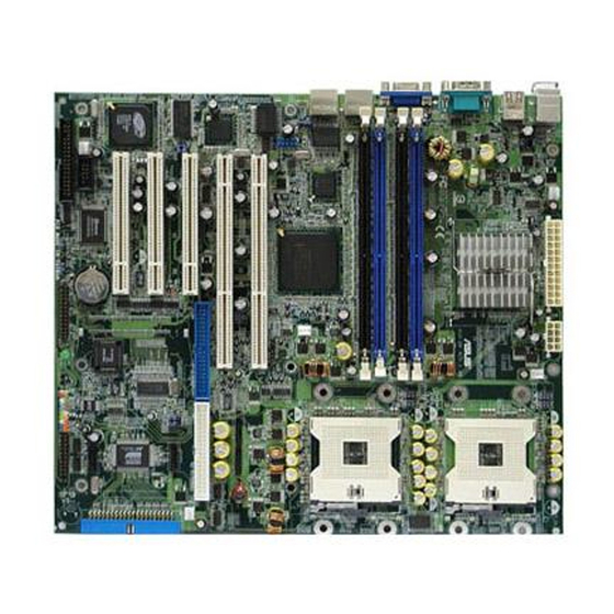
DSW1 PCI2 (32-bit, 33MHz 5V) RAID_EN1 RAGE XL CR2032 3V PCI3 (32-bit, 33MHz 5V) Lithium Cell Controller 4Mbit CMOS Power Flash BIOS AUX_PANEL1 Super BMCCONN1 USBPW34 USB34 SB_PWR1 BUZZER1 PRI_RAID1 COM2 FLOPPY1 CLRTC1 PCH-DR BPSMB1 PANEL1 LPT1 ASUS PCH-DR motherboard... -
Page 22: Layout Contents
2.2.4 Layout Contents Sockets/Slots Page 1. CPU sockets 2. DDR DIMM sockets 2-13 3. PCI/PCI-X slots 2-18 Jumpers 1. Keyboard power (3-pin KBPWR1) 2-19 2. CPU external frequency selection (3-pin DSW1) 2-19 3. USB device wake-up (3-pin USBPW12, USBPW34) 2-20 4. - Page 23 2-33 15. Auxilliary panel connector (20-pin AUX_PANEL1) 2-33 - Front panel SMB (6-1 pin FPSMB) 2-33 - LAN activity LED (2-pin 547_LED, 541_LED) 2-33 - Chassis intrusion (4-1 pin CHASSIS) 2-33 - Locator LED (6-pin LOCATOR) 2-33 ASUS PCH-DR motherboard...
-
Page 24: Central Processing Unit (Cpu)
Central Processing Unit (CPU) 2.3.1 Overview The motherboard comes with dual surface mount 604-pin Zero Insertion Force (ZIF) sockets. The sockets are designed for the Intel ® Xeon™ Processor in the 604-pin package with 1MB/512KB L2 cache. Intel Xeon Gold Arrow Pin A1 PCH-DR PCH-DR CPU Socket 604... - Page 25 CPU. The lever clicks on the side tab to indicate that it is locked. 5. Apply the thermal interface material (thermal grease) to the top of the CPU. This thermal grease should come with the CPU package. ASUS PCH-DR motherboard...
-
Page 26: Installing The Cpu Heatsink And Fan
2.3.3 Installing the CPU heatsink and fan The Intel ® Xeon™ processors require an Intel certified heatsink and fan assembly to ensure optimum thermal condition and performance. When you buy a boxed Intel CPU, the package includes the heatsink, fan, retention brackets, screws, thermal grease, installation manual, and other items that are necessary for CPU installation. - Page 27 4. Position the heatsink on top of the CPU, having its angled side (with cut corners) facing the memory sockets. Make sure that the heatsink base fits completely on the retention mechanism. Heatsink angled side ASUS PCH-DR motherboard...
- Page 28 5. Secure the heatsink with the retention clips. Retention clip a. Insert the center hole of a retention clip into the center tab on the retention mechanism. b. Slightly move the clip to the right so that the center tab is positioned on the narrow side of the hole.
- Page 29 10. Align and insert the side rails of the air tunnel into the grooves on the retention mechanism. NOTE You may need to slightly press out the side of the retention Side rail mechanism to properly insert the air tunnel. Groove (inner side) ASUS PCH-DR motherboard 2-11...
- Page 30 11. Press down the fan and air tunnel assembly until the side rails slide past the grooves and over the rail stoppers. The protruding tab on each corner of the air tunnel should snap over the dents on the retention mechanism. Rail stopper Side rail Protruding tabs...
-
Page 31: System Memory
5. DIMMs installed into any three sockets will function in single- channel mode. 6. When all four sockets are populated with 1GB DIMMs (total 4GB), the system may detect only about 3.6GB (less than 4GB) due to Southbridge resource allocation. ASUS PCH-DR motherboard 2-13... - Page 32 DDR DIMM Type Memory Frequency 533 MHz PC2700/PC2100 333/266 MHz 400 MHz PC2100 266 MHz Obtain DDR DIMMs only from ASUS qualified vendors for better system performance. Visit the ASUS website (www.asus.com) for the latest QVL. 2-14 Chapter 2: Hardware information...
-
Page 33: Installing A Dimm
DIMM. Support the DIMM lightly with your fingers when pressing the retaining clips. The DIMM might get damaged when it flips out with extra force. 2. Remove the DIMM from the socket. ASUS PCH-DR motherboard 2-15... -
Page 34: Expansion Slots
Expansion slots In the future, you may need to install expansion cards. The motherboard has two 64-bit PCI-X slots and three 32-bit PCI slots. The following sub- sections describe the slots and the expansion cards that they support. Make sure to unplug the power cord before adding or removing expansion cards. -
Page 35: Pci Slots
When using PCI cards on shared slots, ensure that the drivers support “Share IRQ” or that the cards do not need IRQ assignments. Otherwise, conflicts will arise between the two PCI groups, making the system unstable and the card inoperable. ASUS PCH-DR motherboard 2-17... -
Page 36: Pci/Pci-X Slots
2.5.3 PCI/PCI-X slots The PCI and PCI-X slots support cards such as a LAN card, SCSI card, USB card, and other cards that comply with PCI/PCI-X specifications. When installing long PCI cards, it is recommended that you install them in PCI slot 1, PCI slot 3, or PCI-X slot 2. Long PCI cards installed in PCI slot 2 and PCI-X slot 1 may interfere with the onboard components. -
Page 37: Jumpers
PCH-DR PCH-DR Keyboard Power Setting 2. CPU external frequency selection (6-pin DSW1) This jumper allows you to select your desired CPU external frequency (or bus clock). DSW1 533MHz 400MHz (Default) PCH-DR PCH-DR CPU External Frequency Selection ASUS PCH-DR motherboard 2-19... -
Page 38: Raid Enable (3-Pin Raid_En)
3. USB device wake-up (3-pin USBPW12, USBPW34) Set these jumpers to +5V to wake up the computer from S1 sleep mode (CPU stopped, DRAM refreshed, system running in low power mode) using the connected USB devices. Set to +5VSB to wake up from S3 and S4 sleep modes (no power to CPU, DRAM in slow refresh, power supply in reduced power mode). -
Page 39: Gigabit Lan1 Controller Setting (3-Pin Lan_En)
This jumper allows you to enable or disable the Intel 82541GI Gigabit LAN controller. Setting this jumper to pins 2-3 disables the Gigabit LAN port 2 (RJ-45) on the rear panel. LAN_EN2 Enable Disable (Default) PCH-DR PCH-DR LAN_EN2 Setting ASUS PCH-DR motherboard 2-21... -
Page 40: Recovery Setting (3-Pin Recovery)
7. Recovery setting (3-pin RECOVERY1) This jumper allows you to update/recover the BIOS quickly. To update the BIOS: 1. Prepare a floppy disk that contains the latest BIOS for the motherboard (xxxx-xxx.BIN) and the AWDFLASH.EXE utility. 2. Set the jumper to pins 2-3. 3. - Page 41 CLRTC1 PCH-DR Normal Clear CMOS (Default) PCH-DR Clear RTC RAM Except when clearing the RTC RAM, never remove the cap on CLRTC jumper default position. Removing the cap will cause system boot failure! ASUS PCH-DR motherboard 2-23...
-
Page 42: Connectors
Connectors 2.7.1 Rear panel connectors 1. PS/2 mouse port. This green 6-pin connector is for a PS/2 mouse. 2. PS/2 keyboard port. This purple connector is for a PS/2 keyboard. 3. USB 2.0 ports 1 and 2. These 4-pin Universal Serial Bus (USB) ports are available for connecting USB 2.0 devices. -
Page 43: Internal Connectors
4-19 for the SATA configuration. SATA1 SATA2 RSATA_TXP1 RSATA_TXP2 RSATA_TXN1 RSATA_TXN2 RSATA_RXP1 RSATA_RXP2 RSATA_RXN1 RSATA_RXN2 PCH-DR PCH-DR SATA Connectors The Serial ATA RAID feature (RAID 0/1) is available only if you are using Windows XP. ASUS PCH-DR motherboard 2-25... -
Page 44: Backplane Smbus Connector (6-1 Pin Bpsmb)
3. IDE connectors (40-1 pin PRI_IDE[blue], SEC_IDE [white) This connector supports the provided UltraDMA/100/66 IDE hard disk ribbon cable. Connect the cable’s blue connector to the primary (recommended) or secondary IDE connector, then connect the gray connector to the UltraDMA/100/66 slave device (hard disk drive) and the black connector to the UltraDMA/100/66 master device. - Page 45 ® 2. The Promise PDC20378 RAID controller does not support ATAPI devices such as CD-ROMs, DVD-ROMs, etc. 3. For RAID 0 and RAID 1 configurations, use both Parallel ATA and Serial ATA devices for better performance. ASUS PCH-DR motherboard 2-27...
- Page 46 CD-ROMs, DVD-ROMs, etc. 2. For RAID 0 and RAID 1 configurations, use both Parallel ATA and Serial ATA devices for better performance. 7. BMC connector (124-pin BMCCONN1) This connector is for ASUS PCI-X server management card, if available. BMCCONN1 PCH-DR...
-
Page 47: Parallel Port Connector (26-Pin Lpt)
9. Parallel port connector (26-pin LPT1) This connector is for a parallel printer. Connect a parallel cable interface (female plug) to this connector, the external port to the printer. Pin 1 LPT1 PCH-DR PCH-DR Parallel Port Connector ASUS PCH-DR motherboard 2-29... - Page 48 10. Serial port 2 connector (10-1 pin COM2) This connector accommodates a second serial port using an optional serial port bracket. Connect the bracket cable to this connector then install the bracket into a slot opening at the back of the system chassis. If you installed a server management card, the COM2 connector becomes a null modem and serves as console.
- Page 49 13. USB 2.0 connector (10-1 pin USB34) This USB connector is available for two additional USB ports. The connector complies with USB 2.0 specification that supports up to 480 Mbps connection speed. USB34 PCH-DR PCH-DR USB 2.0 Connector ASUS PCH-DR motherboard 2-31...
- Page 50 14. System panel connector (20-pin PANEL1) This connector accommodates several system front panel functions. PANEL1 PCH-DR PCH-DR System Panel Connector • System Power LED (3-pin PLED) This lead connects to the system power LED. The LED lights up when you turn on the system power, and blinks when the system is in sleep mode.
-
Page 51: Auxiliary Panel Connector
• Locator LED (6-pin LOCATOR) These leads are for the locator switch and LED on the front panel. ASUS PCH-DR motherboard 2-33... - Page 52 2-34 Chapter 2: Hardware information...
- Page 53 Chapter 3 This chapter describes the power up sequence and gives information on the BIOS beep codes. Powering up...
-
Page 54: Chapter Summary
Chapter summary Starting up for the first time ......3-1 Powering off the computer ......3-2 ASUS PCH-DR motherboard... -
Page 55: Starting Up For The First Time
Motherboard timer not operational Keyboard controller BAT test error General exception error Display memory error CMOS shutdown register read/write error 7. At power on, hold down <Delete> to enter BIOS Setup. Follow the instructions in Chapter 4. ASUS PCH-DR motherboard... -
Page 56: Powering Off The Computer
Powering off the computer 3.2.1 Using the OS shut down function ® ® If you are using Windows 2000 Professional or Windows 2000 Server: 1. Click the Start button then click Shut Down... 2. Make sure that the Shut down option button is selected, then click the OK button to shut down the computer. -
Page 57: Chapter 4: Bios Setup
Chapter 4 This chapter tells how to change system settings through the BIOS Setup menus. Detailed descriptions of the BIOS parameters are also provided. BIOS setup... - Page 58 Chapter summary Managing and updating your BIOS ....4-1 BIOS Setup program ........4-6 Main menu ............4-9 Advanced menu ........... 4-15 Power menu ..........4-28 Boot menu ............ 4-33 Exit menu ............4-38 ASUS PCH-DR motherboard...
-
Page 59: Managing And Updating Your Bios
From the Menu bar, click File > Format. e. Select “Create an MS-DOS Startup Disk” in the Format Options field, then click Start. 2. Copy the original (or the latest) motherboard BIOS to the bootable floppy disk. ASUS PCH-DR motherboard... -
Page 60: Updating The Bios
AwardBIOS Flash Utility. Follow these instructions to update the BIOS using this utility. 1. Download the latest BIOS file from the ASUS web site. Rename the file to *.BIN and save it to a floppy disk. Save only the updated BIOS file in the floppy disk to avoid loading the wrong BIOS file. - Page 61 6. Type the BIOS file name in the File Name to Program field, then press <Enter>. AwardBIOS Flash Utility for ASUS V1.01 (C) Phoenix Technologies Ltd. All Rights Reserved For Canterwood - PSCHSR-IDE DATE: 05/16/2004 Flash Type - SST 49LF004A/B /3.3V File Name to Program : 1001.bin...
-
Page 62: Saving The Current Bios File
9. The utility displays a Flashing Complete message indicating that you have successfully flashed the BIOS file. Press <F1> to restart the system. AwardBIOS Flash Utility for ASUS V1.01 (C) Phoenix Technologies Ltd. All Rights Reserved For Canterwood - PSCHSR-IDE DATE: 05/16/2004 Flash Type - SST 49LF004A/B /3.3V... - Page 63 3. Type a filename for the current BIOS file in the Save current BIOS as field, then press <Enter>. AwardBIOS Flash Utility for ASUS V1.01 (C) Phoenix Technologies Ltd. All Rights Reserved For Canterwood - PSCHSR-IDE DATE: 05/16/2004 Flash Type - SST 49LF004A/B /3.3V File Name to Program : 1001.bin...
-
Page 64: Bios Setup Program
BIOS Setup program This motherboard includes a Flash ROM that you can update using the provided utility described in section “ 4.1 Managing and updating your BIOS.” Use the BIOS Setup program when you are installing a motherboard, reconfiguring your system, or prompted to “Run Setup”. This section explains how to configure your system using this utility. -
Page 65: Bios Menu Screen
For changing the system boot configuration settings Exit For selecting the exit options and loading default settings To select the menu bar items, press the right or left arrow key on the keyboard until the desired item is highlighted. ASUS PCH-DR motherboard... -
Page 66: Navigation Keys
4.2.3 Navigation keys At the bottom of a menu screen are the navigation keys for that particular menu. Use the navigation keys to select items in the menu and change the settings. The navigation keys differ from one screen to another. 4.2.4 General help On the right side of the menu screen is a brief description of the selected item. -
Page 67: Main Menu
Floppy 3 Mode Support [Disabled] This is required to support older Japanese floppy drives. The Floppy 3 Mode feature allows reading and writing of 1.2MB (as opposed to 1.44MB) on a 3.5-inch floppy disk. Configuration options: [Disabled] [Enabled] ASUS PCH-DR motherboard... -
Page 68: Primary Ide Master
Base/Extended/Total Memory [xxxK] The base memory, extended memory, and total memory values are auto- detected. These fields are not user-configurable. 4.3.1 Primary IDE Master Primary Master Select Menu Item Specific Help Auto-Detection [Press Enter] To auto-detect the Primary IDE Master [Auto] HDD’s size, head...on Access Mode... - Page 69 [Mode 0] [Mode 1] [Mode 2] [Mode 3] [Mode 4] UDMA Mode [Auto] When this item is set to [Auto], the UDMA capability allows improved transfer speeds and data integrity for supported IDE drives. Configuration options: [Disabled] [Auto] ASUS PCH-DR motherboard 4-11...
- Page 70 Manually detecting an IDE drive If you wish to manually enter the drive information, set the Primary IDE Master item to [Manual], and the Access Mode item to [CHS]. Primary Master Select Menu Item Specific Help Auto-Detection [Press Enter] Selects the type of Primary IDE Master [Manual] fixed disk connected...
-
Page 71: Primary Ide Slave
When configuring a drive as Secondary IDE Master, refer to section “4.3.1 Primary IDE Master” for the menu item descriptions. 4.3.4 Secondary IDE Slave When configuring a drive as Secondary IDE Slave, refer to section “4.3.1 Primary IDE Master” for the menu item descriptions. ASUS PCH-DR motherboard 4-13... -
Page 72: Third Ide Master
4.3.5 Third IDE Master When configuring a drive as Third IDE Master, refer to section “4.3.1 Primary IDE Master” for the menu item descriptions which are not discussed in this section. Third IDE Master Select Menu Item Specific Help Auto-Detection [Press Enter] Selects the type of Extended IDE Drive... -
Page 73: Advanced Menu
This menu shows the CPU configuration settings. Select an item then press Enter to display a pop-up menu with the configuration options. CPU Configuration Select Menu Item Specific Help CPU L1 & L2 Cache [Enabled] Hyper-Threading Technology [Enabled] Disable/Enable CPU L1/ L2 cache. ASUS PCH-DR motherboard 4-15... -
Page 74: Memory Configuration
CPU L1 & L2 Cache [Enabled] Allows you to enable or disable the CPU L1 and L2 cache. Configuration options: [Disabled] [Enabled] Hyper-Threading Technolody [Enabled] Allows you to enable or disable the CPU Hyper-Threading Technology feature. Set this item to [Enabled] if you are using an operating system that is optimized for Hyper-Threading Technology, such as Windows XP or Linux 2.4. - Page 75 DRAM RAS# Precharge [3] This item controls the idle clocks after issuing a precharge command to the DDR SDRAM. Configuration options: [4] [3] [2] Memory Parity Check [Enabled] Allows memory parity checking option (ECC). Configuration options: [Disabled] [Enabled] ASUS PCH-DR motherboard 4-17...
-
Page 76: Chipset
4.4.3 Chipset This menu shows the chipset configuration settings. Select an item then press Enter to display a sub-menu with additional items, or show a pop-up menu with the configuration options. Chipset Select Menu Item Specific Help Frequency/Voltage Control System BIOS Cacheable [Enabled] Press Enter to set. - Page 77 Sets the ratio between the CPU core clock and the Front Side Bus (FSB) frequency. Key-in a value within the specified range, then press Enter. Configuration options: [Min=12] [Max=18] The minimum and maximum configuration values depend on the installed CPU. ASUS PCH-DR motherboard 4-19...
-
Page 78: Onboard Device
4.4.4 Onboard Device This menu shows the onboard device configuration settings. Select an item then press Enter to display a sub-menu with additional items, or show a pop-up menu with the configuration options. Onboard Device Select Menu Item Specific Help H/W Jumper of CSA LAN ->... -
Page 79: Superio Device
[EPP] [ECP] [ECP+EPP] [Normal] EPP Mode Select [EPP1.7] Allows you to select the EPP mode. This item becomes configurable only if the Parallel Port Mode is set to [EPP] or [ECP+EPP]. Configuration options: [EPP 1.7] [EPP 1.9] ASUS PCH-DR motherboard 4-21... -
Page 80: Sata Configuration
ECP Mode Use DMA [3] Allows you to select the ECP mode. This item becomes configurable only if the Parallel Port Mode is set to [ECP] or [ECP+EPP]. Configuration options: [1] [3] SATA Configuration SATA Configuration Select Menu Item Specific Help *** On-Chip Serial ATA Setting *** On-Chip Serial ATA [Auto]... - Page 81 Configuration options: [Primary Master] [Primary Slave] [Secondary Master] [Secondary Slave] [SATA0 Master] [SATA1 Master] The configuration options for the items Serial ATA Port0 Mode and Serial ATA Port1 Mode vary depending on the On-chip Serial ATA and SATA Mode settings. ASUS PCH-DR motherboard 4-23...
- Page 82 Parallel and Serial ATA hard disk configurations On Primary IDE connector A: Parallel ATA Hard disk 1 B: Parallel ATA Hard disk 2 On Secondary IDE connector C: Parallel ATA Hard disk 3 D: Parallel ATA Hard disk 4 On SATA connectors E: SATA hard disk 1 (SATA1) F: SATA hard disk 2 (SATA2) Setting...
-
Page 83: Pcipnp
Some non-standard VGA cards, like graphics accelerators or MPEG video cards, may not show colors properly. Setting this field to [Enabled] corrects this problem. If you are using a standard VGA card, leave this field to the default setting [Disabled]. Configuration options: [Disabled] [Enabled] ASUS PCH-DR motherboard 4-25... -
Page 84: Irq Resources
INT Pin 1~8 Assignment [Auto] Allows you to select the appropriate interrupt to the specific devices to avoid conflict. Configuration options: [Auto] [3] [4] [5] [7] [9] [10] [11] [12] [14] [15] IRQ Resources Set the item Resources Controlled By to [Manual] to enable the item IRQ Resources and assign the interrupts depending on the type of installed PCI devices. -
Page 85: Usb Configuration
[Enabled] allows the built-in high speed USB support in the BIOS to turn on automatically when you install high speed USB devices. Configuration options: [Disabled] [Enabled] USB Legacy Mode Support [Enabled] Allows you enable or disable support for the legacy USB devices. Configuration options: [Disabled] [Enabled] ASUS PCH-DR motherboard 4-27... -
Page 86: Power Menu
Power menu The Power menu items allow you to change the power management settings. Select an item then press Enter to display the configuration options. Select Menu ACPI APIC Support [Enabled] APM Configuration Item Specific Help Hardware Configuration Enable/Disable ACPI support for Operating System. - Page 87 This item determines when to activate the video off feature for monitor power management. Configuration options: [Yes] [No] MODEM Use IRQ [3] Allows you to select the IRQ assignment for the modem. Configuration options: [NA] [3] [4] [5] [7] [9] [10] [11] ASUS PCH-DR motherboard 4-29...
- Page 88 Soft-Off by PWR-BTTN [Instant-Off] When set to [Instant-Off], the system goes to soft off when you press the power button for less than 4 seconds. When set to [Delay 4 Sec], press the power button for more than 4 seconds to power off the system. Configuration options: [Instant-Off] [Delay 4 Sec.] Power On By PCI Devices [Enabled] Allows you to enable or disable the PME to generate a wake-up event.
-
Page 89: Hardware Monitor
Front Fan1 Speed 0 RPM Fan1 Speed 5152 RPM Fan2 Speed 0 RPM Front Fan2 Speed 0 RPM Rear Fan1 Speed 0 RPM Rear Fan2 Speed 0 RPM The CPU temperatures and fan speeds are auto-detected. ASUS PCH-DR motherboard 4-31... - Page 90 Voltage Monitor Voltage Monitor Select Menu CPU VCORE A (V) 1.45V Item Specific Help +3.3V Voltage 3.20V +12V Voltage 11.79V +1.5V Voltage 1.44V +2.5V Voltage 2.48V +5VCC Voltage 4.82V +5VSB Voltage 4.68V VBAT Voltage 3.07V CPU VCORE Voltage, +3.3V Voltage, +12V Voltage, 1.5V Voltage, 2.5V Voltage, +5VCC Voltage, +5VSB Voltage, VBAT Voltage Auto-detected voltages through the onboard voltage regulators.
-
Page 91: Boot Menu
Select your Boot Device Priority. 1st Boot Device [Removable] 2nd Boot Device [CDROM] 3rd Boot Device [Hard Disk] These items allow you to select your boot device priority. Configuration options: [Removable] [Hard Disk] [CDROM] [Legacy LAN] [Disabled] ASUS PCH-DR motherboard 4-33... -
Page 92: Hard Disk Boot Priority
4.6.2 Hard Disk Boot Priority Hard Disk Boot Priority Select Menu 1. Bootable Add-in Cards Item Specific Help Use <up> or <down> arrow to select a device, then press <+> to move it up, or <-> to move it down the list. -
Page 93: Boot Settings Configuration
[Enabled] clear the case open status. Configuration options: [Disabled] [Enabled] Boot Up Floppy Seek [Enabled] When enabled, the BIOS will seek the floppy disk drive to determine whether the drive has 40 or 80 tracks. Configuration options: [Disabled] [Enabled] ASUS PCH-DR motherboard 4-35... - Page 94 Boot Up NumLock Status [On] Allows you to select the power-on state for the NumLock. Configuration options: [On] [Off] Typematic Rate Setting [Disabled] Allows you to enable or disable the keyboard typematic rate setting. Set to [Enabled] to configure the Type Rate and Type Delay items. Configuration options: [Disabled] [Enabled] The items Typematic Rate (Chars/Sec) and Typematic Delay become configurable only when the item Typematic Setting is enabled.
-
Page 95: Security
2. Press any key to return to the menu. A note about passwords The Supervisor password is required to enter the BIOS Setup program preventing unauthorized access. The User password is required to boot the system preventing unauthorized use. ASUS PCH-DR motherboard 4-37... -
Page 96: Exit Menu
Forgot the password? If you forget your password, you can clear it by erasing the CMOS Real Time Clock (RTC) RAM. The RAM data containing the password information is powered by the onboard button cell battery. If you need to erase the CMOS RAM, refer to section “2.6 Jumpers” for instructions. -
Page 97: Discard Changes
When a confirmation window appears (with a blinking [Y]): • press <Enter> to discard any changes, and load the previously saved values • type [N], then press <Enter>, or simply press <Esc>, to cancel the command and return to the Exit menu ASUS PCH-DR motherboard 4-39... - Page 98 4-40 Chapter 4: BIOS Setup...
-
Page 99: Appendix: Reference Information
Appendix This appendix includes additional information that you may refer to when confiiguring the motherboard. Reference information... - Page 100 Appnedix summary A-1 Block diagram ..........A-1 ASUS PCH-DR motherboard...
-
Page 101: Pch-Dr Block Diagram
LPC BUS 4 USB1.1/2.0 Ports 1 IDE Port (Ultra ATA 66/100) Winbond MINI PCI 83627THF BIOS Super I/O (FWH) Promise PDC20378 1xParallel,Floppy SATA 2xSerial, SATA KB,MS, HW monitor 2 Serial ATA RAID Ports Supports (SATA_RAID1, SATA_RAID2) RAID0/RAID1 ASUS PCH-DR motherboard... - Page 102 Appendix: Reference information...
Need help?
Do you have a question about the PCH DR - Motherboard - Extended ATX and is the answer not in the manual?
Questions and answers