Table of Contents
Advertisement
Operator's Manual
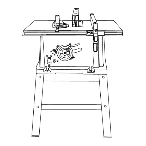
10 in. TABLE SAW
WITH LEG SET
Model No. 137.218020
CAUTION:
Before using this Table Saw,
read this manual and follow
all its Safety Rules and
Operating
Instructions
•
Safety Instructions
•
Installation
•
Operation
•
Maintenance
•
Parts List
Customer
Help
Line
For Technical
Support
1-800-843-1682
Sears
Parts
&
Repair
Center
1-800-488-1222
Sears, Roebuck and Co., Hoffman Estates, IL 60179 USA
Visit our Craftsman
website:
www.sears.com/craftsman
Part No. 137218020001
Advertisement
Table of Contents

Related Manuals for Craftsman 137.218020


Summary of Contents for Craftsman 137.218020
- Page 1 Safety Rules and • Parts List Operating Instructions Sears Parts & Customer Help Line Repair Center For Technical Support 1-800-488-1222 1-800-843-1682 Sears, Roebuck and Co., Hoffman Estates, IL 60179 USA Visit our Craftsman website: www.sears.com/craftsman Part No. 137218020001...
-
Page 2: Specifications
ONE-YEAR FULL WARRANTY ON CRAFTSMAN TOOL If this Craftsman tool fails due to a defect in material or workmanship within one year from the date of purchase, CALL 1-800-4-MY-HOME® TO ARRANGE FOR FREE REPAIR (or replacement if repair proves impossible). -
Page 3: General Safety Instructions
GENERAL S AFETY INSTRUCTIONS Readandunderstand all the instructionsbelowbeforeusingthe powertool. Thesesafetyinstructionsare not meantto cover everypossibleconditionthat could occur. As with any powertool, commonsense,vigilance andduecaremust be used. READ and become familiar with this entire adjusting wrenches are removed from the tool Operator's Manual. LEARN the tool's applications, before turning ON. - Page 4 12. PROVIDE ADEQUATE SUPPORT to the rear ALWAYS USE SAW BLADE GUARD, splitter and anti-kickback pawls for every through-sawing and the sides of the saw table for long or wide operation. Through-sawing operations are those workpieces. in which the blade cuts completely through the 13.
-
Page 5: Grounding Instructions
or a #14 wire with a 15 A time-lag fuse. NOTE: When GROUNDING INSTRUCTIONS using an extension cord on a circuit with a #14 wire, the IN THE EVENT OF A MALFUNCTION extension cord must not exceed 25 feet in length. Before connecting the motor to the power line, make sure the BREAKDOWN, grounding provides a path of least... -
Page 6: Recommended Accessories
I_tL WARNING of Loose Parts" to make certain all items are accounted for, before discarding any packing material. Visit your Sears Hardware Department or see the Craftsman Power and Hand Tools Catalog to IA,WARNING purchase recommended accessories for this power tool. - Page 7 UNPACKING YOUR TABLE "1 "...
-
Page 8: Product View
Blade guard Tableinsert Ripfence Miter gauge Bevel a ngle pointer & scale Blade bevel l ockknob Overload reset switch &tilting hanwheel ON/OFF switch withsafetykey Frontstand Stand mounting holes Anti-kickback pawls Blade Splitter Splitter b racket Rearmounting holes... -
Page 9: Anti-Kickback P Awls
ANTI-KICKBACK P AWLS located on either side of the blade. It helps make - Prevents the workpiece accurate straight or angle crosscuts. from being kicked upward or back toward the front of the table saw by the spinning blade. OVERLOAD RESET SWITCH - Resets the ARBOR - The shaft on which the blade or dado is thermocouple and provides a way to restart the saw... -
Page 10: Assembly/Adjustments
ASSEMBLE TABLE SAW TO STAND (FIG. A-l) ASSEMBLE STAND (FIG. A) 1. Place protective cardboard or old blanket on floor to Unpack all parts and group by type and size. Refer protect the saw table surface. to the parts list for correct quantities. Place the saw up side down on the protective Attach one long upper support (P) to top of leg (S) material (see Fig. -
Page 11: Rip Fence
ASSEMBLE BLADE RAISING & TILTING WHEEL MOUNTED TO WORK SURFACE (FIG.B) If the leg set will not be used, the saw must be (FIG. C) properly secured to a sturdy workbench using the Attach blade raising and tilting hand wheel (1) to the four mounting holes at the base of the saw. -
Page 12: Installing/Changing The Blade
2. Liftupward on ripfencehandle (2)sotherear Fig. H holding clamp(4)is fullyextended. 3. Place theripfenceonthesawtable(5),engaging the rearfenceclamp firstthenlowering t hefrontend ontothetable. 4. Pushdownonthefencehandle (2)to lock. Fig. E Raise the blade arbor (4) (Fig. 1)to the maximum height by turning the blade raising handwheel counterclockwise. -
Page 13: Blade Guard Assembly
Install the saw blade onto the arbor with the blade BLADE GUARD ASSEMBLY (FIG. K, L, M) teeth pointing toward the front of the saw. Set the blade to maximum height and the tilt to zero Install the flange (6) against the blade and thread degrees on the bevel scale with the hand wheels. -
Page 14: Miter Gauge Adjustment
Fig, M If adjustment is needed to make the fence parallel to the groove, proceed with the following adjustments: Kickback pawl • Loosen the two bolts (3) and lift up on the handle (2). • Hold the fence bracket (4) firmly against the front of the saw table. - Page 15 BLADE TILTING MECHANISM BLADE PARALLEL TO THE MITER GAUGE The saw blade can be tilted two different ways. GROOVE (FIG. Q, R) This adjustment was made at the factory, but it should RAPID BLADE TILTING (FIG. P) be rechecked and adjusted if necessary. Loosen blade bevel lock knob (2).
-
Page 16: Adjustment Procedure
ADDITIONAL BLADE ADJUSTMENTS (FIG. R) bolts (3) while holding the rod firmly in place. TOOLS REQUIRED NOTE: The blade alignment rod will only move slightly to the right. • 10 mm open end or 10 mm combination wrench Tighten both middle blade alignment rod strap •... - Page 17 BEVEL POINTER ADJUSTMENT (FIG. T) When you have achieved a 90 ° angle of the blade to the table top as described in section above, the angle pointer (1) may require adjustment. If so, follow proceeding steps: Loosen pointer screw (2) and move the pointer (1) so it is aligned with 0 °...
-
Page 18: Basic Saw Operations
BASIC SAW OPERATIONS across the width or across the grain of the workpiece. Neither ripping nor crosscutting may be done safely ON/OFF SWITCH (FIG. V) freehand. Ripping requires the use of the rip fence, and The on/off switch (1) is located on the front panel of the crosscutting requires the miter gauge. - Page 19 RIPPING SMALL PIECES WARNING la,WARNING AVOID KICKBACK by pushing forward that section of the workpiece that will pass between the blade Avoid injury from the blade contact. Never make and the fence. Use a push stick at all times. through-saw cuts narrower than 3/4 in. wide. Fig, W It is unsafe to rip small pieces.
-
Page 20: Bevel Crosscutting
Fig, Y 1. Set the miter gauge (3) to the desired angle. Place the miter gauge in the right side groove of the table. Set the blade (1) bevel to the desired bevel angle and tighten the blade bevel lock knob. Hold workpiece (2) firmly against the face of the miter gauge throughout the cutting operation. - Page 21 USING WOOD FACING ON THE RIP FENCE (FIG. DADO CUTS (FIG. EE) I,A. WARNING I When performing some special cutting operations, You can add a wood facing (1) to either side of the rip Only Stackable dado blades can be used on this fence (2).
-
Page 22: General Maintenance
GENERAL MAINTENANCE Fig. FF WARNING For your own safety, turn the switch OFF and remove the switch key. Remove the plug from the power source outlet before maintaining or lubricating your saw. Clean out all sawdust that has accumulated inside the saw cabinet and the motor. - Page 23 I_ WARNING To avoid injury from an accidental start, turn the switch OFF and always remove the plug from the power source before making any adjustments, • Consult your local Sears Service Center if for any reason the motor will not run. SYMPTOM POSSIBLE CAUSES CORRECTIVE ACTION...
-
Page 24: Parts Lists/Exploded Views
MODEL NO. 137.218020 WARNING When servicing use only CRAFTSMAN replacement parts. Use of any other parts many create a HAZARD or cause product damage. Any attempt to repair or replace electrical parts on this Table Saw may create a HAZARD unless repair is done by a qualified service technician. - Page 25 10 IN. TABLE SAW SCHEMATIC MODEL NO. 137.218020 \ _29PD I OK3R 2EUC _2FRJ 2FDU OBPA OClt 0821 0B99...
- Page 26 10 IN. TABLE SAW PARTS LIST & SCHEMATIC MODEL NO. 137.218020 STAND Size I.D. No. Description 093B FOOT M8_1.25-35 OJPQ HEX. HD. BOLT M8_1.25 T=7.5 OKRR SERRATED TOOTHED HEXAGON FLANGE 29RE BOTTOM SUPPORT BRACKET 29RF BOTTOM SUPPORT BRACKET 29RS UPPER SUPPORT 29RT UPPER SUPPORT 29RU...
- Page 27 10 IN. TABLE SAW PARTS LIST & SCHEMATIC MODEL NO. 137.218020 MOTOR Size I.D, No. Description Size I.I), No. Description 0HV5 BALL BEARING 6204LLU 0QFG BRUSH HOLDER ASS'Y 0HVU BALL BEARING 6200ZZ OR1S BEARING BUSHING OJX3 HEX SOC SET SCREW M5"08 10ZQ NEEDLE BEARING...
-
Page 28: Push Stick Construction
PUSH STICK CONSTRUCTION • This is a full-size drawing (actual size) • Use good quality plywood or solid wood Use 1/2 in. or 3/4 in. material Push stick MUST be thinner than the width of material being cut Drill Hole For Hanging Notch To Prevent Hand From... - Page 29 Your Home For repair - in your home - of all major brand appliances, lawn and garden equipment, or heating and cooling systems, no matter who made it, no matter who sold it! For the replacement parts, accessories owner's manuals that you need to do-it-yourself. For Sears professional installation of home appliances...
Need help?
Do you have a question about the 137.218020 and is the answer not in the manual?
Questions and answers