Table of Contents
Advertisement
Available languages
Available languages
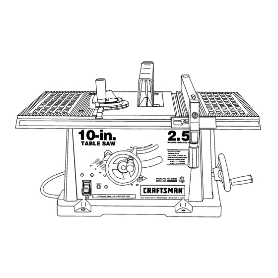
Owner's Manual
2.5 HP (Maximum
Developed)
10" Inch Blade
5000 R.P.M.
TABLE SAW
Model No.
137.218760_
CAUTION:
Before using this Table Saw,
read this manual and follow
all its Safety Rules and
Operating Instructions.
• Safety Instructions
• Installation
• Operation
• Maintenance
• Parts List
• EspaSol
Customer
Help
Line
1-800-843-1682
Sears,
Roebuck
and Co., Hoffman
Estates,
IL 60179
USA
Part No. 137218760001
Advertisement
Table of Contents

Related Manuals for Craftsman 137.218760


Summary of Contents for Craftsman 137.218760
- Page 1 Owner's Manual 2.5 HP (Maximum Developed) 10" Inch Blade 5000 R.P.M. TABLE SAW Model No. 137.218760_ CAUTION: • Safety Instructions • Installation Before using this Table Saw, read this manual and follow • Operation all its Safety Rules and • Maintenance Operating Instructions.
- Page 2 SECTION PAGE Warranty ..............Product Specifications ............. Safety Instructions ............Accessories and Attachments ..........Tools needed for assembly ..........Carton Contents ............Know Your Table Saw ............Assembly and Adjustments ..........Operation .............. Maintenance ............Troubleshooting guide ............ Parts ..............Making a push stick ............
- Page 3 ALWAYS WEAR EYE GENERAL SAFETY INSTRUCTIONS PROTECTION. Any table BEFORE USING THE TABLE SAW saw can throw foreign objects into the eyes which Safety is a combination of common sense, staying alert could cause permanent eye and knowing how to use your table saw. damage.
- Page 4 12. PROVIDE ADEQUATE SUPPORT to the rear and 23. DIRECTION OF FEED. Feed work into a blade or cutter sides of the saw table for wide or long workpieces. against the direction of rotation of the blade or cutter only. 13.
- Page 5 GROUNDING INSTRUCTIONS Fig. A 3-Prong Plug IN THE EVENT OF A MALFUNCTION OR BREAKDOWN, grounding provides a path of least resistance for electric current and reduces the risk of electric shock. This tool is equipped with an electric cord that has an equipment grounding conductor and a grounding plug.
- Page 6 Visit your Sears Hardware Department or see the with the illustration on the next page and the table of Craftsman Power and Hand Tools Catalog to purchase loose parts to make certain all items are accounted for, recommended accessories for this power tool.
- Page 7 UNPACKING YOUR TABLE SAW:...
- Page 8 Blade guard .=insert Miter gauge Rip fence Table l in. Blade tilt pointer TABLE Blade bevel lock knob Blade tilt scale Blade tilting handwheel ON/OFF switch with key Blade elevation handwheel Overload reset switch Mounting holes Kickback pawls Splitter Blade €...
- Page 9 SAW MOUNTED TO WORK SURFACES (FIG. A) Fig. B The saw must be properly secured to a sturdy workbench using the four mounting holes at the base of the saw. The surface of the table where the saw is to be mounted must have a hole large enough to facilitate sawdust fall-through and removal.
- Page 10 RIP FENCE (FIG. E) Raise the blade arbor (4) (FIG. G) to the maximum 1. Thread the fence handle (1) into the cam hole (2) height by turning the blade-raising handwheel until tight. counterclockwise. Lift upward on the rip fence handle (1) so that the Remove the arbor nut (5) and flange (6), remove blade.
- Page 11 BLADE GUARD ASSEMBLY (FIG. I, J, K, L) Check that the nuts (7) that hold the blade guard assembly (8) to the bracket (4) are tight. Tighten if necessary. (FIG. K) To avoid injury from an accidental start, make sure the Fig.
- Page 12 MITER GAUGE ADJUSTMENT (FIG. M) Fig. N Make sure that the miter gauge will slide freely through both table grooves. Loosen the lock knob (1). Set the pointer (2) to the 90 ° mark on the scale. Make a 90° cut in a piece of scrap wood. Check cut piece to see if it was cut at 90 °.
- Page 13 BLADE PARALLEL TO MITER GAUGE Loosen the bevel lock knob. Turn the blade tilting handwheel to move the blade until it is 90° to the GROOVE (FIG. Q, R) table. Adjust the collar (5) so it contacts the bracket (3) This adjustment was made at the factory, but it should when the blade is 90 °...
- Page 14 Additional blade adjustments (FIG. R) If the front and rear measurements are not the same, remove the combination square and loosen the four adjusting screws (1) on the top of the table about a half turn. BASIC SAW OPERATIONS 2. With a folded piece of cardboard covering the blade to protect your hands, move the blade carefully to RAISING THE BLADE (FIG.
- Page 15 r_ Lv_ d2_e To avoid injury, the ON/OFF switch should be in the OFF AVOID KICKBACK by pushing forward only on that section of the workpiece that will pass between the blade position and the plug removed from the power source and the fence.
- Page 16 BEVEL RIPPING Fig. W This cut is the same as ripping except the blade bevel angle is set to an angle other than 0 °. Cut only with the workpiece and the fence on the right side of the blade. RIPPING SMALL PIECES rv_kvAvl__1 _|_II_€...
- Page 17 COMPOUND MITER CROSSCUTTING (FIG.Y) Fig. AA This sawing operation combines a miter angle with a bevel angle. Set the miter gauge (3) to the desired angle. Use ... _3 only the left side groove (2). Set the blade (1) bevel to the desired angle. Carefully push the miter gauge to begin the cutting operation.
- Page 18 MAINTAINING YOUR TABLE SAW Fig. CC GENERAL MAINTENANCE For your own safety, turn the switch OFF and remove the switch key. Remove the plug from the power source outlet before maintaining or lubricating your saw. Clean out all sawdust that has accumulated inside the saw cabinet and the motor.
- Page 19 TROUBLESHOOTING GUIDE To avoid injury from an accidental start, turn the switch OFF and always remove the plug from the power source before making any adjustments. = Consult your local Sears Service Center if for any reason the motor will not run. SYMPTOM POSSIBLE CAUSES...
- Page 20 NO. 137.218760 _€ When servicing use only CRAFTSMAN replacement parts. Use of any other parts may create a HAZARD or cause product damage. Any attempt to repair or replace electrical parts on this Table Saw may create a HAZARD unless repair is done by a qualified service technician.
- Page 21 CRAFTSMAN 10" TABLE SAW MODEL NO. 137.218760 FIGURE A...
- Page 22 CRAFTSMAN 10" TABLE SAW MODEL NO. 137.218760 PARTS LIST FOR FIGURE B Key No. PART NUMBER Description Size 14911602 Knob 2501NZDN 16 Flat washer 1/4 x 3/4-1/64 14911402 Head 14608001 L--20 14911802 Ang!e pointer 29835L5006 _teel ball 14523301 Compression spring 2603BBLA38 Hex.
- Page 23 CRAFTSMAN 10" TABLE SAW MODEL NO. 137.218760 FIGURE B...
- Page 24 CRAFTSMAN 10" TABLE SAW MODEL NO. 137.218760 PARTS LIST FOR FIGURE C Key No. PART NUMBER Description Size 14921001 Saddle 14921703 Bracket 2501NBDN03 Flat washer 3/16 x 3/8-0.022 2617BBLC11 Hex. soc. hd. cap screw M5 x 0.8-20 2615BZDD25 Hex hd. screw and washer M8 x 1.25-16...
- Page 25 CRAFTSMAN 10" TABLE SAW MODEL NO. 137.218760 FIGURE...
- Page 27 :_-_ ....
- Page 29 _!0 Io ,-o._ C_." _ "_ "-- ___o...
- Page 31 [_1_ WARNING Some dust created by power sanding, sawing, grinding, drilling and other construction activities contains chemicals known to cause cancer, birth defects or other reproductive harm. Some examples of these chemicals are: Lead from lead-based paints • Crystalline silica from bricks, cement and other masonry products •...
- Page 32 For in-home major brand repair service: Call 24 hours a day, 7 days a week 1-800-4-MY-HOME" (1-800-469-4663) Para pedir servicio de reparaci6n a domicilio - 1-800-676-5811 In Canada for all your service and parts needs call - 1-800-665-4455 Au Canada pour tout le service ou les pi_ces For the repair or replacement parts you need: Call 6 a.rn.
- Page 33 Manual de Operacibn CRRFTSMRN" 2.5 HP (Potencia Mdxima) Hoja Circular de 25.4cm (10") 5000 R.P.M. SIERRA DE MESA Modelo No. 137.218760 10.in. TABLE CUIDADO: • Instrucciones de Seguridad • InstalaciSn Antes de usar esta Sierra de Mesa, leer este manual y seguir todas sus •...
- Page 34 SECCION PAGINA Garantia ..............Especificaciones de la Herramienta .......... Instrucciones de Seguridad ..........Accesorios y Aditamentos ..........Herramientas necesarias para el ensamblaje ........Contenido de la Caja ............Familiarizarse con la Sierra de Mesa .......... Ensamblaje y Regulacibn ........... Operacibn ...............
- Page 35 INSTRUCCIONES GENERALES DE USAR SIEMPREUSAR PROTECCION SEGURIDAD PARALOS OJOS.Cualquier sierrade mesa puedearrojar objetos extrafiosa los ojos ANTES DE USAR LA SIERRA DE MESA causandodafios serios permanentes.SIEMPRE Laseguridades una combinaci6nde sentidocom_n, mantenerse usar Gafas de Seguridad(no alerta y conocer como funciona la sierrade mesa. anteojos) que cumplan con la normaZ87.1 de ANSI.Los anteojos de uso diario s61otienen lentes resistentesa los impactos,estos NO SON gafas de seguridad.Las Galas...
- Page 36 12. PROVEER SOPORTE ADECUADOen las partes posterior 23. AVANZAR la pieza de trabajo s61oen direcci6n contraria y laterales de la hoja cuando se corten piezas anchas a la rotaci6n de la hoja. o largas. 24. ADVERTENCIA"El polvo generado por ciertos materiales 13.
- Page 37 INSTRUCCIONES PARA LA CONEXION A TIERRA Fig. A Enchufe de 3 espigas EN EL EVENTO DE UNA FALLA O MAL FUNCIONAMIENTO, la conexi6n a tierraproveeunavfa de menorresistencia parala corriente electrica,reduciendo asf el riesgo de choqueel_ctrico. Estaherramienta est,. equipadacon uncord6nelectrico que tiene un conductor p ara conexi6n a tierray tambiencon un enchufecon espigaparael misrno fin.
- Page 38 ACCESORIOS RECOMENDADOS DESEMBALAJE Y VERIFICACION DEL CONTENIDO Visitar el Departamento de Ferreterfade la tienda Sears mas Separar todas las piezas de sus envolturas.Antes de descartar cercana over el Cat_.logode Herramientas El_ctricas/Neum_.ticas cualquier material de embalaje, verificar las piezas contra la y Manualesde Sears para comprar los accesorios recomendados ilustraci6n en la siguiente p_.ginay la lista a continuaci6n para ver para esta herramienta.
- Page 39 DESEMBALAJE DE LA SIERRA DE MESA: lO.in.
- Page 40 Cubierta protectora de la hoja Inserto de la mesa Medidor de _n( de corte en inglete Barrera Mesa lO-in. Aguja indicadora de inclinaci6n de la hoja TABLE SAW Manija de fijaci6n del Escala de inclinaci6n de la hoja Interruptor con Ilave de la hoja =_-_ Manivela elevadora...
- Page 41 MONTAJEDE LA SIERRA EN OTRAS SUPERFICIES (FIG.A) La sierradebe montarsey sujetaradecuadamente a un banco Fig. B de trabajorobusto usandoloscuatroorificios para pernosde montaje que est_n en la base de la sierra. En la superficie donde se monte la sierra, debe hacerse un orificio Io suficientemente grande para que caiga el aserrfn y poderlo sacar.
- Page 42 Subir el eje portasierra (4) (Fig. G) al mdximogirando la BARRERA(FIG. E) manivela elevadoracontra el sentido del reloj. Enroscar el mango (1) de la barrera en orificio (2) de la leva Sacar la tuerca del eje portahoja (5) y la brida (6), remover hasta que ajuste.
- Page 43 ENSAMBLAJE DEL PROTECTOR DE LA HOJA (FIG.I, J, K, L) Verificarque las tuercas (7) que sujetan el protector (8) de la hoja del soporte separador(4) est6n ajustadas.Ajustar si fuese necesario. 'IV;Ill,J: :ii=_ [q W Fig. K Para evitar lesiones debidas a un arranque accidental de la sierra, cerciorarseque el interruptor est_ en "OFF"...
- Page 44 REGULACIONDEL MEDIDOR DE ANGULOS DE CORTE EN Fig. N INGLETE (FIG. M) Cerciorarse que el medidordel angulo de corteen ingletese deslicelibremente porambasranurasde la mesa. Aflojar la perilla (1). Colocar el indicador (2) en la marca de 900en la escala. Usando un pedazode madera de desecho, hacer un corte a k_.._ k__ ___ k_ 90°.
- Page 45 PARALELISMODE LA HOJA CON LA RANURA DEL Aflojar la perilla de fijaci6n del angulo de corte en bisel hasta que la hoja est_ a 900con la mesa. MEDIDORDE CORTE EN INGLETE (FIG. Q, R) Ajustar la brida (5) para que _aga contactocon el soporte (3) Esta regulaci6nfue hecha en fabrica,pero debe revisarsey cuando la hoja este a 90°...
- Page 46 Ajustesadicionales de la hoja (FIG.R) Si la medida de la distancia en el frente y atra_s no es igual, retirar la escuadracombinada y aflojarlos cuatropernos de fijaci6n (1) que esta.n sobrela mesaaproximadamente mediavuelta. OPERACIONES BASICAS DE CORTE Con un pedazode cart6ndoblado cubriendo la hojapara protegerse las manos, moverla hoja cuidadosamente a la izquierdao la derechatantocomosea necesario para ELEVACIONDE LA HOJA (FIG.
- Page 47 '!V__lilvl ='1 / :_ [1_ [ Para evitar lesiones, mientrasel motor se est_ enfriando, el Para EVITAR QUE LA SIERRA "PATEE" la pieza de trabajo en interruptor debe estar en la posici6n de "OFF" (Apagado) y se retroceso, solamenteempujarla desde la secci6n que pasara entre debe desenchufarel cord6n del tomacorriente para evitar un la hoja y la barrera.
- Page 48 CORTE BISELADOA LO LARGO DE LA HEBRA Fig. W Este cortese haceigualque el cortea Io largode la hebra, exceptoque el a.ngulode corte en biselno es 0°. '!Y;lllll: ;I i: _[e_ I Cortar enicamente con la pieza de trabajo y la barrera en el lado derecho de la hoja.
- Page 49 CORTE CRUZADO COMBINADO(FIG.Y) Consiste en combinar un corte en bisel y en inglete a la vez. Graduarel medidor de _ngulo (3) para corteen ingleteal Fig. AA _.ngulodeseado. U sar enicamente la ranuraizquierda(2) de la mesa. Regularla hojaal _.ngulo(1) deseadoparacorte en bisel. Para comenzar el corte,empujarla piezade trabajo cuidadosamente p er el medidor de inglete.
- Page 50 MANTENIMIENTO DE LA SIERRA DE MESA Fig. CC MANTENIMIENTOGENERAL r!V;! elVj: :i / = _[e,]! Para evitar lesiones causadas por arranques inesperadosde la sierra y quitar la Ilave del interruptor.Desconectarel enchufe del tomacorriente antes de hacerle mantenimientoo lubricar la sierra. Eliminar el aserrfn que se acumula dentro del gabinete de la sierra yen el motor.
- Page 51 GU|A PARA EL DIAGNOSTICO DE PROBLEMAS '!V.,I I_vj:1;I I ;I _[o]! Para evitar lesiones por arranques accidentalesde la sierra, siempre colocar el interruptor en la posici6n de "OFF"y desenchufarel cord6n del tomacorriente antes de lubricaro hacerle cualquier regulaci6na la sierra. •...
- Page 52 DE MESA DE 10" MODEL NO. 137.218760 AI darle servicio a la m_.quina s61ousar de repuestos CRAFTSMAN.El uso de cualquier otto repuesto puede crear RIESGOS o dahar la herramienta.CualquierJntentode reparar o reemplazar las piezas electricas de esta sierra de mesa puede crear RIESGOSa menos que la reparaci6nla haga un t_cnico calificado de servicio.Se dispone de servicio de reparaci6nen el centro de Servicio de...
- Page 53 SIERRA DE MESA DE 10 MODEL NO. 137.218760 FIGURAA I"- !iii31_!d_!'! ilii i i !difi ¸¸:! _;IP _!d...
- Page 54 LISTA DE PARTES DE LA SIERRA DE MESA DE 10" MODEL NO. 137.218760 LISTADE PARTESCORRESPONDIENTEA LA FIGURA B No. Diag. No. Parte Descripci6n Tama_o Cantidad 14911602 Perilla 2501NZDN 16 Arandela plana 1/4 x 3/4-1/64 14911402 Cabezal 14608001 Clavi ja L=20 14911802 Puntero indicador de _ngulo 29835L5006...
- Page 55 SIERRA DE MESA DE 10 MODEL NO. 137.218760 FIGURA B ¢,0...
- Page 56 LISTA DE PARTES DE LA SIERRA DE MESA DE 10" MODEL NO. 137.218760 LISTADE PARTESCORRESPONDIENTEA LA FIGURA C TamaEo Cantidad No. Diag. No. Parte Descripci6n 14921001 Montura 14921703 Soporte 2501NBDN03 Arandela plana /516 x 3/8-0.022 2617BBLC 11 Perno prislonero hex. x 0.8-20 2615BZDD25 Perno Hex.
- Page 57 SIERRA DE MESA DE 10 MODEL NO, 137.218760 FIGURA C...
- Page 58 WARNING Some dust created by power sanding, sawing, grinding, drilling and other construction activities contains chemicals known to cause cancer, birth defects or other reproductive harm. Some examples of these chemicals are: Lead from lead-based paints Crystalline silica from bricks, cement and other masonry products...
- Page 59 For in-home major brand repair service: Call 24 hours a day, 7 days a week 1-800-4-M Y-H 0 M E°° (1-800-469-4663) Para pedir servicio de reparaci6n a domicilio - 1-800-676-5811 In Canada for all your service and parts needs call - 1-800-665-4455 Au Canada pour tout le service ou les pi_ces For the repair or replacement parts you need"...
Need help?
Do you have a question about the 137.218760 and is the answer not in the manual?
Questions and answers