Table of Contents
Advertisement
Available languages
Available languages
FCC-B Radio Frequency Interference Statement
This equipment has been tested and found to comply with the limits for a class B digital device, pursuant to part
15 of the FCC rules. These limits are designed to provide reasonable protection against harmful interference
when the equipment is operated in a commercial environment. This equipment generates, uses and can
radiate radio frequency energy and, if not installed and used in accordance with the instruction manual, may
cause harmful interference to radio communications. Operation of this equipment in a residential area is likely
to cause harmful interference, in which case the user will be required to correct the interference at his own
expense.
Notice 1
The changes or modifications not expressly approved by the party responsible for compliance could void the
user's authority to operate the equipment.
Notice 2
Shielded interface cables and A.C. power cord, if any, must be used in order to comply with the emission limits.
VOIR LA NOTICE D'NSTALLATION AVANT DE RACCORDER AU RESEAU.
This device complies with Part 15 of the FCC Rules. Operation is subject to the following two conditions:
(1) this device may not cause harmful interference, and
(2) this device must accept any interference received, including interference that may cause undesired
operation
Micro-Star International
MS-7142
G52-M7142X1
i
Advertisement
Table of Contents

Related Manuals for MSI K8MM-V


Summary of Contents for MSI K8MM-V
- Page 1 FCC-B Radio Frequency Interference Statement This equipment has been tested and found to comply with the limits for a class B digital device, pursuant to part 15 of the FCC rules. These limits are designed to provide reasonable protection against harmful interference when the equipment is operated in a commercial environment.
-
Page 2: Copyright Notice
Copyright Notice The material in this document is the intellectual property of MICRO-STAR INTERNATIONAL. We take every care in the preparation of this document, but no guarantee is given as to the correctness of its contents. Our products are under continual improvement and we reserve the right to make changes without notice. Trademarks All trademarks are the properties of their respective owners. -
Page 3: Safety Instructions
Safety Instructions 1. Always read the safety instructions carefully. 2. Keep this User Manual for future reference. 3. Keep this equipment away from humidity. 4. Lay this equipment on a reliable flat surface before setting it up. 5. The openings on the enclosure are for air convection hence protects the equipment from overheating. Do not cover the openings. - Page 4 Table of Content English..............1 Deutsch..............17 Français..............33 简体中文 ..............49 繁體中文 ..............63 日本語...............77...
- Page 5 Series is based on VIA ® K8M800-CE & VT8237R chipsets for optimal system efficiency. Designed to fit the advanced AMD ® K8 Athlon64 processors in 754 pin package, the K8MM-V Series delivers a high performance and professional desktop platform solution.
-
Page 6: Specifications
Specifications Supports 64-bit AMD®K8 Athlon64 processor (Socket 754) Supports 3700+ and higher CPU (For the latest information about CPU, please visit http://www.msi.com.tw/program/products/mainboard/mbd/pro_mbd_cpu_support.php ) Chipset VIA®K8M800-CE Chipset -HyperTransport connection to AMD K8 Athlon64 processor - 8 or 16 bit control/address/data transfer both directions - 800/600/400/200 MHz “Double Data Rate”... - Page 7 On-Board IDE An IDE controller on the VIA®VT8237R chipset provides IDE HDD/CD-ROM with PIO, Bus Master and Ultra DMA 66/100/133 operation modes Can connect up to 4 IDE devices Serial ATA/150 controller integrated by VT8237R - Up to 150MB/s transfer rate - Can connect up to two serial ATA devices On-Board Peripherals On-Board Peripherals include:...
- Page 8 BIOS The mainboard BIOS provides “Plug & Play” BIOS which detects the peripheral devices and expansion cards of the board automatically. The mainboard provides a Desktop Management Interface (DMI) function that records your mainboard specifications. Dimension Micro-ATX Form Factor: 243mm x 195mm. Mounting 6 mounting holes.
-
Page 9: Hardware Setup
If you do not have the heat sink and cooling fan, contact your dealer to purchase and install them before turning on the computer. (For the latest information about CPU, please visit http://www.msi.com.tw/program/products/mainboard/mbd/pro_mbd_cpu_support.php ) Example of CPU Core Speed Derivation Procedure CPU Clock... -
Page 10: Memory Speed/Cpu Fsb Support Matrix
Memory Speed/CPU FSB Support Matrix Memory DDR 266 DDR 333 DDR 400 800 MHz CPU Installation Procedures for Socket 754 Please turn off the power and unplug the power cord before installing the CPU. Pull the lever sideways away from the socket. Make sure to raise the lever up to a 90-degree angle. - Page 11 Fasten down the lever. Make sure the safety hook completely clasps the fixed bolt of the retention mechanism. MSI Reminds You... While disconnecting the Safety Hook from the fixed bolt, it is necessary to keep an eye on your fingers, because once the Safety Hook is disconnected from the fixed bolt, the fixed lever will spring back instantly.
-
Page 12: Power Supply
Volt Notch Power Supply The mainboard supports ATX power supply for the power system. Before inserting the power supply connector, always make sure that all components are installed properly to ensure that no damage will be caused. A 300W or above power supply is suggested. 10 20 5V_SB ATX 20-Pin Power Connector: CONN1... -
Page 13: Fan Power Connectors: Cpufan1/Sfan1
GND. If the mainboard has a System Hardware Monitor chipset on-board, you must use a specially designed fan with speed sensor to take advantage of the CPU fan control. MSI Reminds You... 1. Always consult the vendors for proper CPU cooling fan. -
Page 14: Front Panel Audio Connector: Jaud1
AUD_MIC AUD_MIC_BIAS MSI Reminds You... If you do not want to connect to the front audio header, pins 5 & 6, 9 & 10 have to be jumpered in order to have signal output directed to the rear audio ports. Otherwise, the Line-Out connector on the back panel will not function. -
Page 15: Serial Port Connector: Jcom1 (Optional)
Serial Port Connector: JCOM1 (Optional) The main board offers one serial port COM2. It is 16550A high speed communication port that sends/receives 16 bytes FIFOs. You can attach a serial mouse or other serial device directly to it. SIGNAL DESCRIPTION SIGNAL DESCRIPTION Data Carry Detect... -
Page 16: Clear Cmos Jumper: Jbat1
JBAT1 (Clear CMOS Jumper) to clear data. Follow the instructions below to clear the data: MSI Reminds You... You can clear CMOS by shorting 2-3 pin while the system is off. Then return to 1-2 pin position. Avoid clearing the CMOS while the system is on;... -
Page 17: Bios Setup
BIOS Setup Power on the computer and the system will start POST (Power On Self Test) process. When the message below appears on the screen, press <DEL> key to enter Setup. DEL: Setup F11: Boot Menu TAB: Logo If the message disappears before you respond and you still wish to enter Setup, restart the system by turning it OFF and On or pressing the RESET button. - Page 18 Load Optimized Defaults Use this menu to load factory default settings into the BIOS for stable system performance operations. BIOS Setting Password Use this menu to set BIOS setting Password. Save & Exit Setup Save changes to CMOS and exit setup. Exit Without Saving Abandon all changes and exit setup.
- Page 19 Cell Menu Current CPU Clock It shows the current clock of CPU. Read-only. Cool’n’Quiet control It provides a CPU temperature detecting function to prevent your CPU’s from overheading due to the heavy working loading. Memory Voltage (V) Adjusting the DDR voltage can increase the DDR speed. Any changes made to this setting may cause a stability issue, so changing the DDR voltage for long-term purpose is NOT recommended.
- Page 21 Mainboard basiert auf den VIA ® K8M800-CE und VT8237R Chipsätzen und ermöglicht so ein optimales und effizientes System. Entworfen, um die fortschrittlichen AMD ® K8 Athlon64 Prozessoren im 754 Pin- Package aufzunehmen, stellt das K8MM-V Series die ideale Lösung zum Aufbau eines professionellen Hochleistungsdesktopsystems dar.
-
Page 22: Spezifikationen
Spezifikationen Unterstützt 64-Bit AMD®K8 Athlon64 Prozessoren (Sockel 754) Unterstützt 3700+ CPUs und höher (Um die neuesten Informationen zu unterstützten Prozessoren zu erhalten, besuchen Sie bitte http://www.msi.com.tw/program/products/mainboard/mbd/pro_mbd_cpu_support.php ) Chipsatz VIA®K8M800-CE Chipsatz - HyperTransport Anbindung an den AMD K8 Athlon64 Prozessor - Bidirektionale Übertragung von Adress-/Steuerinformationen und Daten mit 8 oder 16 Bit - 800/600/400/200 MHz “Double Data Rate”... - Page 23 Onboard IDE Der im VIA®VT8237R Chipsatz enthaltene IDE Kontroller bietet für den Festplatten- und CD-ROM-Zugriff PIO, Bus Mastering und Betrieb mit Ultra DMA 66/100/133 Bis zu vier IDE Geräte anschließbar Serial ATA/150 Kontroller in den VT8237R integriert - Übertragungsrate von bis zu 150MB/s - Bis zu zwei Serial ATA Laufwerke anschließbar Peripherieanschlüsse onboard hierzu gehören:...
- Page 24 BIOS Das Mainboard- BIOS verfügt über “Plug & Play”- Funktionalität, mit der angeschlossene Peripheriegeräte und Erweiterungskarten automatisch erkannt werden. Das Mainboard stellt ein Desktop - Management - Interface (DMI) zur Verfügung, welches automatisch die Spezifikationen Ihres Mainboards aufzeichnet. Abmessungen Micro-ATX Form Faktor: 243mm x 195mm Montage 6 Montagebohrungen...
-
Page 25: Hinteres Anschlusspaneel
Sie über keinen Kühlkörper mit aktivem Prozessorlüfter, setzen Sie sich bitte mit Ihrem Händler in Verbindung, um einen solchen zu erwerben und danach zu installieren, bevor Sie Ihren Computer anschalten. (Um die neuesten Informationen zu unterstützten Prozessoren zu erhalten, besuchen Sie bitte http://www.msi.com.tw/program/products/mainboard/mbd/pro_mbd_cpu_support.php) - Page 26 Beispiel zur Ermittlung des Kerntaktes Wenn externer CPU-Takt 200 MHz Kern-/Systemtaktmultiplikator dann ist Kerntakt externer CPU-Takt x Kern/Sytemtaktmultiplikator 200 MHz 2,4 GHz Tabelle unterstützte Speichergeschwindigkeit/CPU FSB Speicher DDR 266 DDR 333 DDR 400 800 MHz Vorgehensweise beim CPU-Einbau beim Sockel 754 Bitte schalten Sie das System aus und ziehen Sie den Netzstecker, bevor Sie die CPU einbauen.
- Page 27 Drücken Sie den Sicherungshebel herab. Stellen Sie sicher, dass der Sicherungshaken den Sicherungsbolzen des Rückhaltemechanismus vollständig umschließt. MSI weist darauf hin... Es besteht Verletzungsgefahr, wenn Sie den Sicherungshaken vom Sicherungsbolzen trennen. Sobald der Sicherungshaken gelöst wird, schnellt der Sicherungshaken sofort zurück.
- Page 28 Betrieb mindestens ein DIMM- Speichermodul ein. Um den letzten Stand bezüglich der unterstützten Speichermodule zu erhalten, besuchen Sie bitte http://www.msi.com.tw/program/products/mainboard/mbd/pro_mbd_trp_list.php Setzen Sie mindestens ein DIMM- Speichermodul ein. Gemäß Ihren Anforderungen können Sie entweder ein- oder doppelseitige Module in beliebiger Reihenfolge verwenden .
- Page 29 Überwachung der Systemhardware und Steuerung der Lüfter versehen, dann brauchen Sie einen speziellen Lüfter mit Tacho, um diese Funktion zu nutzen. MSI weist darauf hin... 1. Bitten Sie stets Ihren Händler bei der Auswahl des geeigneten CPU Kühlers um Hilfe.
- Page 30 Setzen einer Steckbrücke als Slave eingestellt werden. IDE2 kann ebenfalls je ein Master- und ein Slave- Laufwerk verwalten. MSI weist darauf hin... Verbinden Sie zwei Laufwerke über ein Kabel, müssen Sie das zweite Laufwerk im Slave- Modus konfigurieren, indem Sie entsprechend den Jumper setzen. Entnehmen Sie bitte die Anweisungen zum Setzen des Jumpers der Dokumentation der Festplatte, die der Festplattenhersteller zur Verfügung...
- Page 31 MSI weist darauf hin... Wenn Sie die vorderen Audioanschlüsse nicht verwenden, müssen die Pins 5 & 6 und 9 & 10 mit sog. „Jumpern“ gebrückt werden, um die Signalausgabe auf die hinteren Audioanschlüsse umzuleiten. Andernfalls ist der Line -Out Ausgang im hinteren Anschlussfeld ohne Funktion.
- Page 32 Gehäusekontaktschalter: JCASE1 GN D C I NT RO Dieser Anschluss wird mit einem 2-poligen Gehäusekontaktschalter verbunden. Wird das Gehäuse geöffnet, wird der Schalter geschlossen. Das System zeichnet dies auf. Um die resultierende Warnung zu löschen, müssen Sie das BIOS aufrufen und dort den Warnzustand zurücksetzen.
-
Page 33: Pci Interrupt Request Routing
MSI weist darauf hin... Sie können den CMOS löschen, indem Sie die Pins 2-3 verbinden, während das System ausgeschaltet ist. Kehren Sie danach zur Pinposition 1-2 zurück. Löschen Sie den CMOS nicht, solange das System angeschaltet ist, dies würde das Mainboard beschädigen. -
Page 34: Bios Setup
BIOS Setup Nach dem Einschalten beginnt der Computer den POST (Power On Self Test - Selbstüberprüfung nach Anschalten). Sobald die Meldung unten erscheint, drücken Sie die Taste <Entf>(<Del>), um das Setup aufzurufen. DEL: Setup F11: Boot Menu TAB: Logo Wenn die Nachricht verschwindet, bevor Sie reagieren und Sie möchten immer noch ins Setup, starten Sie das System neu, indem Sie es erst AUS- und danach wieder ANSCHALTEN, oder die “RESET”-Taste am Gehäuse betätigen. - Page 35 PNP/PCI Configurations Dieser Eintrag erscheint, wenn Ihr System Plug and Play- Geräte am PCI-Bus unterstützt. H/W Monitor Dieser Eintrag gibt den „Gesundheitszustand“ Ihres PCs wieder. Cell Menu Hier können Sie Einstellungen zu Taktfrequenz und Spannung vornehmen. Load Optimized Defaults In diesem Menü können Sie die Werkseinstellungen für stabilen Systembetrieb in das BIOS laden. BIOS Setting Password Verwenden Sie dieses Menü, um das Kennwort für das BIOS einzugeben.
- Page 36 Cell Menu Current CPU Clock Zeigt die derzeitigen Taktung der CPU an. Nur Anzeige. Cool’n’Quiet control Stellt eine Funktion zur Erfassung der CPU Temperatur bereit, um Ihre CPU vor Überhitzung durch hohe Last zu bewahren. Memory Voltage (V) Die Spannung des DDR anzuheben, kann diesen beschleunigen. Jede Änderung dieser Option kann zu Stabilitätsproblemen führen, deswegen wird von einer langfristigen Änderung der DDR Spannung ABGERATEN.
- Page 37 Félicitation vous venez d’acheter la carte mère micro ATX K8MM-V Series (MS-7142 v1.X). La K8MM-V est basée sur les chipsets VIA ® K8M800-CE & VT8237R permettant ainsi d’offrir des performances optimales, de plus elle fonctionne avec les processeurs AMD ® K8 Athlon64 (socket 754).
-
Page 38: Spécifications
Supporte DDR266/333/400 DDR SDRAM (184 broches) DDR DIMMs. Supporte un maximum de mémoire de 2GB (Pour nue mise à jour sur les modules de mémoires supportés, veuillez visiter http://www.msi.com.tw/program/products/mainboard/mbd/pro_mbd_trp_list.php ) Slots Un slot AGP (Accelerated Graphics Port). - Compatible avec les spécifications AGP 3.0... - Page 39 IDE Intégré Un contrôleur IDE intégré dans le chipset VIA®VT8237R procure IDE HDD/CD-ROM avec PIO, Bus Master et les modes opératoires Ultra DMA 66/100/133 Possibilité de connecter jusqu’à 4 matériels IDE Contrôleur Serial ATA/150 intégré dans le VT8237R - Taux de transfert jusqu’à 150MB/s - Possibilité...
- Page 40 BIOS Le BIOS de la carte mère est Plug & Play, par conséquent il est en mesure de détecter automatiquement les périphériques ou cartes d’extensions La carte mère procure une fonction DMI (Desktop Management Interface) qui mémorise les spécificités de la carte mère Dimension Format Micro-ATX : 243mm x 195mm Montage...
-
Page 41: Panneau Arrière
Pour connaître le modèle de ventilateur nécessaire à la bonne utilisation de votre système n’hésitez pas à contacter votre revendeur. (Pour connaître les dernières informations concernant le CPU, veuillez visiter http://www.msi.com.tw/program/products/mainboard/mbd/pro_mbd_cpu_support.php ) Exemple de Dérivation du CPU Core Speed Horloge CPU... - Page 42 Table de Support CPU/Vitesse Mémoire Mémoire DDR 266 DDR 333 DDR 400 800 MHz Procédure d’Installation du CPU Socket 754 Veuillez éteindre ou débrancher le PC avant d’installer le CPU. Tirer le levier qui se trouve sur le côté du socket. Assurez-vous que celui-ci est bien relevé (position 90°).
- Page 43 2GB. Pour fonctionner correctement il faut au moins installer un module de mémoire sur un DIMM. (Pour une mise à jour sur les modules de mémoire supportés, veuillez visiter : http://www.msi.com.tw/program/products/mainboard/mbd/pro_mbd_trp_list.php ) Les modules de mémoire peuvent être simples ou doubles, installez les selon vos besoins.
- Page 44 Alimentation La carte mère supporte les alimentations ATX. Avant de brancher le connecteur d’alimentation. Il faut toujours vous assurer que tous les composants sont bien installés 10 20 afin de ne pas les endommager. Une alimentation 300W ou 5V_SB supérieur est préconisée. PW_OK Connecteur d’Alimentation ATX 20 broches : PS_ON...
- Page 45 MSI Vous Rappelle... 1 Il faut toujours consulter votre revendeur au sujet du ventilateur. 2. CPUFAN1 supportent le contrôle de la vitesse ede rotation. Vous pouvez installer PC Alert pour contrôler automatiquement la vitesse du ventilateur en fonction de la température du CPU.
- Page 46 MSI Vous Rappelle... Si vous ne voulez pas connecter l’audio en façade à l’aide des broches 5 & 6, 9 & 10 doivent être recouvertes par un cavalier pour envoyer le signal vers les ports audio à l’arrière. Autrement, le connecteur Line-Out à...
- Page 47 JBAT1 (Clear CMOS Jumper). Suivez les instructions ci-dessous pour effacer les données : MSI Vous Rappelle... Vous effacez les données en positionnant le cavalier sur les broches 2-3 quand le PC n’est pas allumé. Puis il faut remettre le cavalier en position 1-2. Ne surtout pas effacer les données (position 2-3)
- Page 48 Slot AGP (Accelerated Graphics Port) Le slot AGP vous permet de connecter une carte graphique. Cette interface est particulièrement bien adaptée aux applications 3D. Contrôleur 66MHz, 32-bit avec accès direct à la mémoire principale. Slots PCI (Peripheral Component Interconnect) Les slots PCI vous permettent la connexion de cartes d’extension selon vos besoins. Pour installer ou retirer une carte PCI, il faut que le PC soit éteint.
-
Page 49: Page Principale
BIOS Lorsque le PC démarre le processus de POST (Power On Self Test) se met en route. Quand le message ci-dessous apparaît, appuyer sur <DEL> pour accéder au Setup. DEL: Setup F11: Menu de Boot F12: Boot réseau TAB: Logo Si le message disparaît avant que n’ayez appuyé... - Page 50 Cell Menu Utilisez ce menu pour spécifier les paramètres que vous désirez utiliser en ce qui concerne le contrôle fréquence/voltage. Load Optimized Defaults Utiliser le menu pour charger les paramètres par défaut pour obtenir un système stable et performant. BIOS Setting Password Utiliser ce menu pour entrer un mot de passe pour le BIOS.
- Page 51 Cell Menu Current CPU Clock Vous montre l’horloge du CPU. Lecture uniquement. Cool’n’Quiet control Procure une fonction de détection de la température du CPU pour éviter la surchauffe lors de charges dfe travail importantes. Memory Voltage (V) Modifier le voltage DDR peut augmenter la vitesse de la DDR. Cependant les changements peuvent entraîner une instabilité, c’est pour cela que nous ne recommandons pas ce genre d’usage à...
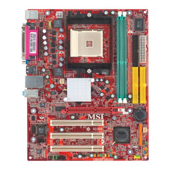
- Page 53 简介 感谢您购买 K8MM-V Series ( MS-7142 v1.X) micro ATX 主板。 K8MM-V Series 是基于 VIA ® K8M800-CE 和 VT8237R 芯片组, 是为 754 针脚封装的 AMD ® K8 Athlon64 处理器量身定做的高性能主板。 K8MM-V Series 提供了高性能、专业化的桌面平台解决方案。 布局 JPW1 JCASE1 Top : mouse Bottom: keyboard Winbond W83627THF...
- Page 54 规格 支持 64-bit AMD® K8 Athlon64 处理器(Socket 754) 支持 3700+及更高频率的 CPU (要了解关于 CPU 的最新信息,请访问 http://www.msi.com.tw/program/products/mainboard/mbd/pro_mbd_cpu_support.php ) 芯片组 VIA®K8M800-CE 芯片组 - HyperTransport 连接到 AMD K8 Athlon64 处理器 - 8 或 16 bit 控制/地址/数据双向传输 - 800/600/400/200 MHz“双倍数据速率”双向工作 - AGP v3.0 符合 8x 传输模式...
- Page 55 最多可连接 4 个 IDE 设备 Serial ATA/150 控制器集成于 VT8237R 中 - 传输速率高达 150MB/s - 最多可连接 2 个 serial ATA 设备 板载周边 板载周边包括: - 1 个软驱接口,支持 1 台 360K, 720K, 1.2M, 1.44M 和 2.88 Mbytes 的软驱 - 1 个串行端口(COMA) - 1 个 VGA 端口 - 1 个并行端口,支持...
-
Page 56: 中央处理器:Cpu
设备的指导,如鼠标,键盘等。安装时,请谨慎拿各零部件并且按照安装说明的步骤进行。 中央处理器:CPU ® 本主板支持 AMD Athlon64 处理器。主板使用的是 Socket-754 的 CPU 插槽,可使 CPU 安装过程简化。 当您在安装 CPU 时, 请务必确认您使用的 CPU 带有防过热的散热片和降温风扇。 如果您的 CPU 没有散 热片和降温风扇,请与销售商联系,购买或索取以上设备,并在开机之前妥善安装。 (要了解关于 CPU 的最新信息,请访问 http://www.msi.com.tw/program/products/mainboard/mbd/pro_mbd_cpu_support.php ) CPU 核心速度推导 CPU 时钟频率 200MHz 如果 核心/总线倍频 CPU 核心频率 主时钟频率 x 核心/总线倍频... - Page 57 剥开后板的贴纸。 翻转主板,把后板安装到正确位置。 再次翻转主板,把主板放置到平稳的平台。找到后板的两个螺丝孔。 对齐固定装置和后板。用两个螺丝把固定装置和后板固定住。 把散热装置放到固定装置上,先勾住夹子的一端。 按下夹子的另一端,把风扇装置固定到固定装置。 找到连接杠杆、固定螺栓和安全吊钩。提起连接杠杆。 下压并扣住此杠杆。请确认安全吊钩已完全扣紧到固定装置的固定螺栓。 连接 CPU 风扇电源线到主板上的 CPU 风扇接口。 微星提醒您... 当安全吊钩未与固定栓连接时,请注意您的手指。因为一旦安全钩与固定栓脱离固定,固定杆将会立即 弹出。 内存 主板提供了 2 个 184-pin 的无缓冲 DDR266/DDR333/DDR400 DDR SDRAM , 支持的最大容量为 2GB。 您至少要安装一条内存在插槽,以保证系统正常工作。 (要了解内存模组支持的最新信息,请访问 http://www.msi.com.tw/program/products/mainboard/mbd/pro_mbd_trp_list.php ) 每条插槽支持的最大容量为 1GB,您可以根据自己的需求安装单面或双面的内存。 安装 DDR 内存 DDR DIMM 内存条的中央仅有一个缺口。...
- Page 58 将 DDR 内存垂直插入 DDR 插槽中,并确保缺口的正确位置。 DIMM 插槽两边的塑料卡口会自动闭合。 Volt Notch 电源适配器 主板使用 ATX 结构的电源适配器给主板供电。在连接电源适配器之前,请务必确认所有的组件都已正确 安装,并且不会造成损坏。建议您使用功率为 300W 或以上的电源。 10 20 5V_SB ATX 20-Pin 电源接口:CONN1 PW_OK 此接口可连接 ATX 电源适配器。在与 ATX 电源适配器相连时,请务必 确认,电源适配器的接头安装方向正确,针脚对应顺序也准确无误。 PS_ON 将电源接头插入,并使其与主板电源接口稳固连接。 -12V 3.3V 3.3V 3.3V ATX 12V 电源接口:JPW1 此 12V 电源接口用于为 CPU 供电。 软盘驱动器接口:FDD1 主板提供了一个标准的软盘驱动器接口...
- Page 59 扇)支持+12V 的系统散热风扇,可使用 3 -pin 的接头。当您将接线接到风扇接头时,请注意红色线为正 极,必须接到+12V,而黑色线是接地,必须接到 GND。如果您的主机板有系统硬件监控芯片,您必须使 用一个特别设计的支持速度侦测的风扇方可使用此功能。 微星提醒您... 请询问厂商以使用适当的 CPU 降温风扇。 CPUFAN1 支持风扇控制, 您可以安装 PC Alert 工具, 这样就可让系统根据 CPU 温度自动控制 CPU 风扇速度。 IDE 接口:IDE1/IDE2 主板有 2 个 32-bit 增强 PCI IDE 和 Ultra DMA 33/66/100/133 控制器 , 支持 PIO 模式 0~4, Bus Master 和...
- Page 60 微星提醒您... 如果您不想使用前置音频,针脚 5 & 6, 9 & 10 必须用跳线帽短接,这样输出信号才会转到后面的音频端 口。否则后面的 Line-Out 音频接口将不起作用。 USB0- 前置 USB 接口:JUSB1/JUSB2 USB0+ 主板提供 2 个 USB2.0 的接口。USB 2.0 技术提高数据传输速度,达到 480Mbps, 是 USB1.1 的 40 倍。它可连接高速数据传输速率的 USB 界面周边设备,如 USB HDD、数码相机、MP3 播放器、打印机、调制解调器等。 USB1+ USB1- 微星提醒您... 请注意,VCC 和 GND 的针脚必须安插正确,否则会引起主板的损毁。 串行接口:JCOM1(选配)...
- Page 61 Serial ATA 硬盘接口:SATA1/SATA2 主板提供 2 个高速串行 Serial ATA 端口。每个接口都支持第一代 Serial ATA,数 SATA2 据速率达到 150 MB/s。两个接口都兼容 Serial ATA1.0 规格,且都可连接 1 台 Serial ATA 硬盘设备。 SATA1 SIGNAL SIGNAL 清除 CMOS 跳线:JBAT1 主板上建有一个 CMOS RAM, 其中保存的系统配置数据需要通过一枚 Clear Data Keep Data 外置电池来维持。CMOS RAM 是在每次启动计算机的时候引导操作系统的。若您想清除保存在 CMOS RAM 中的系统配置信息,可使用...
- Page 62 AGP(加速图像端口)插槽 AGP 插槽可让您插入 AGP 显卡, 它是专为 3D 图 形显示而设计的一种接口规范。它为图形控制器对主内存的直接访问提供一个 66MHz,32-bit 专用通道。 PCI(周边设备连接)插槽 PCI 插槽可安装您所需要的扩展卡。当您在安装或拆卸扩展卡的时候,请务必确认已将电源插头拔除。 同时,请仔细阅读扩展卡的说明文件,安装和设置此扩展 卡必须的硬件和软件,比如跳线或 BIOS 设置。 PCI 中断请求队列 IRQ 是中断请求队列和中断请求确认的缩写,将设备的中断信号送到微处理器的硬件列表。PCI 的 IRQ 针脚一般都是连接到如下表所示的 PCI 总线的 INT A# ~ INTD# 引脚: Order1 Order2 Order3 Order4 PCI Slot 1 INT A# INT B# INT C# INT D#...
- Page 63 BIOS 设置 计算机加电后,系统将会开始 POST (加电自检)过程。当屏幕上出现以下信息时,按<DEL>键即可进 入设定程序。 DEL: Setup F11: Boot Menu TAB: Logo 如果信息在您做出反应前就消失了,而您仍需要进入 Setup,请关机后再开机或按机箱上的 Reset 键, 重 启您的系统。您也可以同时按下<Ctrl>、<Alt>和<Delete>键来重启系统。 主页面 Standard CMOS Features(标准 CMOS 特性设定) 使用此菜单可对基本的系统配置进行设定。如时间,日期等。 Advanced BIOS Features(高级 BIOS 特性设定) ® 使用此菜单可对 Award 系统的高级特性进行设定。 Advanced Chipset Features(高级芯片组特性设定) 使用此菜单可以修改芯片组寄存器的值,优化系统的性能表现。 Integrated Peripherals(整合周边设定) 使用此菜单可以对周边设备进行特别的设定。...
- Page 64 Load Optimized Defaults(载入优化设置缺省值) 使用此菜单可以载入系统优化性能设置的 BIOS 值,但此缺省值可能会影响系统的稳定性。 BIOS Setting Password(BIOS 设置密码) 使用此项以设定 BIOS 设置密码。 Save & Exit Setup(保存后退出) 保存对 CMOS 的修改,然后退出 Setup 程序。 Exit Without Saving(不保存退出) 放弃对 CMOS 的修改,然后退出 Setup 程序。...
- Page 65 核心菜单 Current CPU Clock(当前 CPU 时钟) 在此项中,显示了 CPU 的当前频率,只读。 Cool’n’Quiet control(Cool’n’Quiet 控制) 此项可侦测 CPU 温度,避免 CPU 由于超负荷运行而过热。 Memory Voltage (V) (内存电压,V) 调整 DDR 电压可以提高 DDR 速度。但这样的调整会影响系统的稳定性,所以建议您不要改变默认设置 作为长期使用。 AGP Voltage (V) (AGP 电压,V) AGP 电压可在此项做调整,可让您在超频时提高 AGP 卡的性能,但这样会影响系统的稳定性。所以建 议您不要改变默认设置作为长期使用。 设定值从 1.5V 到 1.8V,以 0.05V 为单位。 Auto Detect PCI Clk(自动侦测...
- Page 67 簡介 感謝您購買 K8MM-V Series ( MS-7142 v1.X) micro ATX 主機板 。 K8MM-V Series 採用 VIA ® K8M800-CE 和 VT8237R 晶片組,是為 754 針腳封裝的 AMD ® K8 Athlon64 處理器設計的高性能主機板。 K8MM-V Series 提供了高性能、專業化的桌面平臺解決方案。 主機板配置圖 JPW1 JCASE1 Top : mouse Bottom: keyboard Winbond W83627THF...
- Page 68 規格 支援 64-bit AMD® K8 Athlon64 處理器(Socket 754) 支援 3700+及更高頻率的 CPU (要瞭解關於 CPU 的最新資訊,請至微星科技網站 http://www.msi.com.tw/program/products/mainboard/mbd/pro_mbd_cpu_support.php ) 晶片組 VIA®K8M800-CE 晶片組 - HyperTransport 連接到 AMD K8 Athlon64 處理器 - 8 或 16 bit 控制/位址/資料雙向傳輸 - 800/600/400/200 MHz“雙倍數據速率”雙向工作 - AGP v3.0 符合 8x 傳輸模式...
- Page 69 最多可連接 4 個 IDE 設備 Serial ATA/150 控制器整合於 VT8237R 中 - 傳輸速率高達 150MB/s - 最多可連接 2 個 serial ATA 設備 板載周邊 板載周邊包括: - 1 個軟碟機介面,支援 1 台 360K, 720K, 1.2M, 1.44M 和 2.88 Mbytes 的軟碟機 - 1 個序列埠(COMA) - 1 個 VGA 埠 - 1 個平行埠,支援...
-
Page 70: 中央處理器:Cpu
本章將教您安裝中央處理器、記憶體模組、擴充卡及設定主機板上的跨接器。附帶並告訴您如何連接滑 鼠鍵盤等週邊裝置。進行安裝時請小心處理零組件並遵守安裝步驟。 中央處理器:CPU ® 本主機板支援 AMD Athlon64 處理器。主機板使用的是 Socket-754 的 CPU 插槽,可使 CPU 安裝過程 簡化。當您在安裝 CPU 時,請務必確認您使用的 CPU 帶有防過熱的散熱片和降溫風扇。如果您的 CPU 沒有散熱片和降溫風扇,請與銷售商聯繫,購買或索取以上設備,並在開機之前妥善安裝。 (要瞭解關於 CPU 的最新資訊,請至微星科技網站 http://www.msi.com.tw/program/products/mainboard/mbd/pro_mbd_cpu_support.php ) CPU 核心速度調整說明 CPU 時脈 200MHz 如果 核心/匯流排比值 CPU 速度 那麼 主時脈 x 核心/匯流排比值 200MHz x 12 2.4 GHz... - Page 71 翻轉主機板,把背板安裝到正確位置。 再次翻轉主機板,把主機板放置到平穩的平臺。找到背板的兩個螺絲孔。 對齊固定裝置和背板。用兩個螺絲把固定裝置和後板固定住。 把散熱裝置放到固定裝置上,先勾住夾子的一端。 按下夾子的另一端,把風扇裝置固定到固定裝置。 找到連接槓桿、固定螺栓和安全吊鉤。提起連接槓桿。 下壓並扣住此槓桿。請確認安全吊鉤已完全扣緊到固定裝置的固定螺栓。 連接 CPU 風扇電源線到主機板上的 CPU 風扇介面。 微星提醒您... 當安全吊鉤未與固定栓連接時,請注意您的手指。因為一旦安全鉤與固定栓脫離固定,固定桿將會立即 彈出。 記憶體 主板提供了 2 個 184-pin 的無緩衝 DDR266/DDR333/DDR400 DDR SDRAM , 支援的最大容量為 2GB。 您至少要安裝一條記憶體在插槽,以保證系統正常工作。 (要瞭解記憶體模組支援的最新資訊,請至微星 http://www.msi.com.tw/program/products/mainboard/mbd/pro_mbd_trp_list.php 科技網站 ) 每條插槽支援的最大容量為 1GB,您可以根據自己的需求安裝單面或雙面的記憶體。 安裝 DDR 記憶體 DDR DIMM 記憶體條的中央僅有一個缺口。...
- Page 72 將 DDR 記憶體垂直插入 DDR 插槽中,並確保缺口的正確位置。 DIMM 插槽兩邊的塑膠卡口會自動閉合。 Volt Notch 電源功供應器 本主機板的電源系統支援 ATX 電源。在插入電源連接器之前,請務必確認所有的零組件均安裝妥善,以 免造成損壞。我們建議您使用 300 瓦以上的電源供應器。 10 20 5V_SB ATX 20-Pin 電源連接器:CONN1 PW_OK 此連接器讓您接上 ATX 電源。連接 ATX 電源時,請確認電源插頭插入 的方向正確並對準腳位,然後將電源緊密地壓入連接器內。 PS_ON -12V 3.3V ATX 12V 電源連接器:JPW1 3.3V 3.3V 12V 的電源連接器是供中央處理器使用。 軟碟機連接器:FDD1 本主機板提供了標準的軟碟機連接器,可以連接以下類型的軟碟機:360KB、720KB、1.2MB、...
- Page 73 風扇接頭時,請注意紅色線為正極,必須接到+12V,而黑色線是接地,必須接到 GND。如果您的主機板 有系統硬體監控晶片,您必須使用一個特別設計的支援速度偵測的風扇方可使用此功能。 微星提醒您... 請詢問廠商以使用適當的 CPU 降溫風扇。 CPUFAN1 支援風扇控制 , 您可以安裝 PC Alert 工具 , 這樣就可讓系統根據 CPU 溫度自動控制 CPU 風扇速度。 IDE 連接器:IDE1/IDE2 本主機板具有一個 32 位元增強型 PCI IDE 及 Ultra DMA 33/66/100/133 控制器,可提供 PIO 模式 0~4、 主控匯流排以及 Ultra DMA 33/66/100/133 等功能。你可透過 IDE 連接線連接四部硬碟、CD-ROM 及其 他...
- Page 74 微星提醒您... 假如您在同一條連接線上安裝了兩組硬碟,您必須設定硬碟的跨接器(Jumper) ,將第二組硬碟指定到隸 屬模式。關於硬碟的設定方式,請參考硬碟廠商所提供之說明。 USB0- 面板 USB 連接器:JUSB1/JUSB2 USB0+ 主機板提供兩個面板 USB2.0 連接器 JUSB1/JUSB2,其規格都符合 Intel 面板輸入 /輸出設計指南。USB2.0 技術可大幅提昇資料傳輸速率,最高可達 480Mbps,為 USB1.1 的 40 倍,適用於高速 USB 介面的週邊裝置,例如:USB 硬碟、數位相機、 USB1+ MP3 播放器、印表機、數據機及相關週邊裝置。 USB1- 微星提醒您... 請注意,VCC 和 GND 的針腳必須安插正確,否則會引起主機板的損毀。 序列埠連接器:JCOM1(選購) 主板提供 1 個串列針腳 JCOM1 , 它是 16550A 高速通信埠的針腳 。 序列埠可收發 16 bytes FIFO,可用來連接串列滑鼠或其他串列設備。...
- Page 75 Serial ATA 硬碟連接器:SATA1/SATA2 主機板支援 2 個序列連接器 SATA1&SATA2 。SATA1 & SATA2 提供高速的 Serial SATA2 ATA 介面連接埠 。 透過第一代 Serial ATA 的介面可提供高達 150 MB/s 的傳輸率, 每個 Serial ATA 介面可連接一組硬碟機且均完全相容於 Serial ATA 1.0 的規範。 SATA1 SIGNAL SIGNAL 清除 CMOS 跨接器:JBAT1 主機板上有一個 CMOS RAM,它是利用主機板上的水銀電池來保存 Clear Data Keep Data BIOS 的設定。CMOS RAM 可以讓系統在每次開機的時候,依照使用者...
- Page 76 AGP 插槽 此插槽能讓您安裝 AGP 顯示卡。AGP 的設計是一個可提升 3D 繪圖處理效能的介面規格。它採用一個 66MHz、32 位元的頻寬當作圖形控制器和主記憶體之間的直接通道。此插槽支援支援 4x AGP 顯示卡。 PCI 插槽 此插槽可以讓您安裝各類擴充卡,以滿足你的使用需求。當您要安裝或是移除擴充卡時,請先確認電源 已切斷。另外,請詳讀擴充卡的使用說明,以確認在使用擴充卡時所需要變更的硬體或軟體設定,例如 跨接器、開關或 BIOS 的組態與設定。 PCI 的中斷要求 IRQ 是中斷要求 (Interrupt request) 的英文縮寫,它是一個可讓裝置傳送中斷訊號至微處理器的硬體線 路。PCI 的 IRQ 腳位通常都連接到 PCI 匯流排的 INT A#~INT D#腳位,如下所示: Order1 Order2 Order3 Order4 PCI Slot 1 INT A# INT B#...
- Page 77 BIOS 設置 打開電腦的電源後,系統就會開始 POST (開機自我測試)程序。當下列訊息出現在螢幕上時,按下<DEL> 鍵進入設定程式。 DEL: Setup F11: Boot Menu TAB: Logo 如果此訊息在您反應之前就已消失,而您還想要進入設定時,將系統關閉重新啟動或是按下 RESET 按 鈕。您也可以同時按下 <Ctrl>、<Alt>及<Delete>鍵重新啟動系統。 主頁面 Standard CMOS Features(標準 CMOS 設定) 使用此選單設定基本的系統組態,例如時間、日期等。 Advanced BIOS Features(進階 BIOS 設定) 使用此選單設定 Award 特殊的進階功能選項。 Advanced Chipset Features(進階晶片組功能) 使用此選單變更晶片組暫存器中的數值,並將系統效能最佳化。 Integrated Peripherals(整合型週邊) 使用此選單指定整合型週邊裝置的設定。 Power Management Features (電源管理功能)...
- Page 78 Load Optimized Defaults(載入理想化預設值) 使用此功能清單載入 BIOS 的出廠預設值,以獲得最穩定的系統作業。 BIOS Setting Password(設定 BIOS 密碼) 使用此選單設定 BIOS 密碼。 Save & Exit Setup(儲存並離開設定) 將變更儲存到 CMOS 並離開設定程式。 Exit Without Saving(離開但不儲存) 放棄所有 CMOS 變更並離開設定程式。...
- Page 79 核心菜單 Current CPU Clock(當前 CPU 時脈) 在此項中,顯示了 CPU 的當前頻率,唯讀。 Cool’n’Quiet control(Cool’n’Quiet 控制) 此項可偵測 CPU 溫度,避免 CPU 由於超負荷運行而過熱。 Memory Voltage (V) (記憶體電壓,V) 調整 DDR 電壓可以提高 DDR 速度。但這樣的調整會影響系統的穩定性,所以建議您不要改變預設值作 為長期使用。 AGP Voltage (V) (AGP 電壓,V) AGP 電壓可在此項做調整,可讓您在超頻時提高 AGP 卡的性能,但這樣會影響系統的穩定性。所以建 議您不要改變預設值作為長期使用。 設定值從 1.5V 到 1.8V,以 0.05V 為單位。 Auto Detect PCI Clk(自動偵測...
- Page 81 Introduction K8MM-V シリーズ(MS-7142 v1.X) micro ATX マザーボードをお買い上げいただきまことにあり がとうございます。 K8MM-V シリーズは VIA ® K8M800-CE & VT8237R チップセットに基づい ています。 Socket754 ピンパッケージの AMD® K8 Athlon64 プロセッサのデザインに準拠してい る K8MM-V シリーズはハイ・パフォーマンスおよびプロフェッショナル・デスクトップ・ソリ ューションを提供します。 レイアウト JPW1 JCASE1 Top : mouse Bottom: keyboard Winbond W83627THF JWR2 Top : Parallel Port...
- Page 82 マザーボードの仕様 Socket 754、 64 ビットの AMD K8 Athlon 64 プロセッサをサポート 3700+あるいはそれ以上のプロセッサをサポート (最新の CPU 対応表は下記のホームページからご参考ください。 http://www.msi.com.tw/program/products/mainboard/mbd/pro_mbd_cpu_support.php ) チップセット VIA®K8M800-CE チップセット -AMD K8 Athlon64 プロセッサへの HyperTransport 接続 - 8 か 16 ビットの双方向コントロール/アドレス/データ転送操作モード - 800/600/400/200 MHz の”Double Data Rate”双方向操作モード - AGP v3.0 準拠の 8X 転送モード...
- Page 83 オンボード IDE VIA®VT8237R チップセットの IDE コントローラが IDE HDD/CD-ROM に対して PIO、バス マスタ、Ultra DMA 66/100/133 オペレーションモードをサポート IDE デバイスを 4 つまで接続 VT8237R に統合したシリアル ATA/150 コントローラ - 最大 150MB/sec 転送速度 - 最大 2 個のシリアル ATA ドライブをサポート オンボード周辺装置 オンボード周辺装置は以下のものを含みます - 1 フロッピーポートで 360K、720K、1.2M、1.44M バイトの FDD1 個接続可能 - 1 シリアルポート...
- Page 84 BIOS 本製品の BIOS は接続された周辺機器や装着された拡張カードを自動的に認識する Plug & Play BIOS を提供 DMI (Desktop Management Interface)機能によりメインボードの仕様を記録. 寸法 Micro-ATX フォーム・ファクタ: 243mm x 195mm. 取付 取付穴×6...
- Page 85 ってコンポーネントが破損する場合があります。 Central Processing Unit: CPU 本製品は AMD Athlon64 プロセッサで動作します。本製品は Socket 754 というソケットを使用 しているため、CPU のインストールが大変簡単です。CPU の過剰な発熱を防ぐためには必ずヒ ートシンクと冷却ファンが必要です。 ヒートシンクと冷却ファンが取り付けられていないときは、 ヒートシンクと冷却ファンを購入し、 取り付けてから、 コンピュータの電源を投入してください。 (最新の CPU 対応表は下記のホームページからご参考ください。 http://www.msi.com.tw/program/products/mainboard/mbd/pro_mbd_cpu_support.php ) CPU コアクロックの設定 CPU Clock 200MHz Core/Bus ratio then CPU core speed Host Clock x Core/Bus ratio...
- Page 86 メモリタイプ/CPU FSB サポート対応表 Memory DDR 266 DDR 333 DDR 400 800 MHz Socket 754 CPU のインストール手順 CPU を装着する前に必ず電源スイッチをオフにし、電源コードを抜いてください。 レバーをソケットから横方向に引っ張ってください。そのままレバーを持ち上げるように してソケットとの角度が 90 度になるまで開きます。 ソケットのピン 1 と CPU の白い点か端が欠けている場所を確認してください。それらを 合わせるようにして CPU をソケットに挿入してください。 CPU がしっかりと装着されているのなら、ピンが見えないようになります。CPU が正し く装着されない場合、マザーボードに厳重なダメージを与えることになります。 CPU を奥まで押して、ソケットにしっかりと嵌めてから、レバーを閉じてください。レバ ーが完全に閉じる前に、CPU を押した手を離さないでください。 AMD Athlon64 CPU クーラーセットのインストール手順 プロセッサ技術の進歩によりスピードと性能が上がるにつれて温度管理がますます重要になっ...
- Page 87 に取り付けます。 そして、反対側にあるクリップも下に押し下げて、ヒートシンクを固定します。 固定レバー、安全フックと固定ボルトの位置を確認します。そして、固定レバーを時計回 りの方向で回します。 安全フックを固定ボルトに引っかかるまで回します。 最後は安全フックがしっかりと固定されているかどうかを確認し、 CPU ファンが固定の装 着作業が完了します。 MSI Reminds You... CPU ファン固定用の安全フックには、強い弾力性のある素材が使用されています。ロックを解 除した瞬間に元の位置に弾け飛ぶように戻り、指などを挟む危険性がありますので、十分注意し ながら作業してください。 メモリ 本製品には、184 ピン DDR SDRAM DIMM(Double In-Line Memory Module)モジュールを差し込 むソケットが 2 個あり、最大 2GB のメモリがサポートされます。 (最新のメモリモジュール対応表は下記のホームページからご参考ください。 http://www.msi.com.tw/program/products/mainboard/mbd/pro_mbd_trp_list.php ) DDR DIMM スロット(DDR 1、2)上、PC3200/DDR400、PC2700/DDR333、PC2100/DDR266 モ ジュールをインストールすることができます。 DDR DIMM スロットには絵に描いてあるような"VOLT"の切れ込みがあります。 このため、...
- Page 88 電源 メインボードでは、給電システムとして ATX 電源がサポートされています。電源コネクタをイ ンストールする前に、ボードに損傷が与えられないようにするため、すべてのコンポーネントが 適切にインストールされていることを確認してください。 10 20 ATX 20-ピン電源コネクタ: CONN1 5V_SB PW_OK このコネクタを使用すると、ATX 電源に接続することができま す。ATX 電源へ接続するには、電源のプラグが正しい方向に挿 入され、 ピンが適切に配置されていることを確認します。 そして PS_ON 電源をコネクタの奥まで差し込みます。 -12V 3.3V 3.3V 3.3V ATX 12V 電源コネクタ: JPW1 この 12V 電源コネクタは、CPU への電源供給で使用されます。 フロッピーディスクコネクタ: FDD1 本製品は 360K、720K、1.2M、1.44M 及び 2.88M のフロッピーディスクドライブに対 応しています。このコネクタは付属のフロッピドライブリボンケーブルをサポートし...
- Page 89 MSI Reminds You.. 1. 適切な冷却ファンについては、ベンダーにお問い合わせください。 2. CPUFAN1 はファンコントローラをサポートしています。 ハードディスクコネクタ: IDE1/IDE2 本製品には、PIO 0~4 モード、Bus Master、Ultra DMA 33/66/100/133 機能をもつ、32 ビット Enhanced PCI IDE および Ultra DMA 33/66/100/133 コントローラを搭載してい ます。最大 4 つのハードディスク、CD-ROM、120MB フロッピー、その他のデバイスを 接続することができます。 1 台目の HDD は必ず IDE1(プライマリ)に接続します。IDE1 にはマスターとスレイブの 2 つ IDE/ATAPI のデバイスを接続することができますが、 2 台目の HDD を追加する場合...
- Page 90 MSI Reminds You... フロント・パネル・オーディオ・ヘッダに接続しない場合、信号の出力が背面オーディオ・ポー トへ送信されるようにするため、ピン 5、6、9、10 はジャンパでキャップする必要があります。 フロント USB コネクタ: JUSB1/JUSB2 USB0- USB0+ 本製品には 2 つの USB 2.0 ピン・ヘッダーJUSB1&JUSB2 が搭載されてい ます。USB 2.0 テクノロジーでは、最大スループット 480Mbps までデータ 伝送率を高速化するため、USB 1.1 の 40 倍高速になります。USB ハードデ ィスク、デジタル・カメラ、MP3 プレーヤ、プリンタ、モデム、その他の高 USB1+ USB1- 速 USB インタフェース周辺機器へ接続することができます。 MSI Reminds You...
- Page 91 JCASE1 ケース開放センサーコネクタ: このコネクタは 2 ピンのケーススイッチに接続されます。ケースが開けられ GN D C I NT RO ると、ケース開放センサーはショートになります。システムはこの状態を記 録し、警告メッセージを画面に表示します。この警告メッセージをクリアにするには、BIOS Setup ユーティリティに入って状態の記憶を消去しなければなりません。 SPDIF Out コネクタ: JSP1 このコネクタは、 デジタル・オーディオ伝送を対象とした SPDIF(Sony & Philips Digital Interconnect Format)インタフェースへ接続するために使用 SPDIF します。. シリアル ATA HDD コネクタ: SATA1/SATA2 SATA1 と SATA 2 はデュアルの高速 シリアル ATA インターフェイスポ SATA2 ートを搭載します。これらのポートは第一世代...
- Page 92 クリア CMOS ジャンパ: JBAT1 本製品は電池によって、マザーボードの設定を CMOS RAM で保 Clear Data Keep Data 存しています。JBAT1 の 1-2 ピンがショートしている時、CMOS データをキープしています。マザーボードの CMOS の内容をクリアするためには電源が入って いないときに 2-3 ピンをショートさせます。 MSI Reminds You... CMOS をクリアするには、システムがオフの間にピン 2-3 をショート(短絡)します。次いでピン 1-2 をショートに戻します。システム起動時の CMOS のクリアは絶対止めて下さい。マザーボ ードの破損や火災などに及ぶ危険があります。必ず電源コードを抜いて下さい。...
- Page 93 AGP (Accelerated Graphics Port) スロット AGP スロットは AGP グラフィックカードだけを 挿すことができます。AGP とは 3D グラフィッ クの処理能力の需要のために開発されたインターフェイス規格です。 グラフィックコントローラ が 66MHz、32 ビットチャンネルを利用してメインメモリに直接アクセスすることができます。 PCI (Peripheral Component Interconnect) スロット PCI スロットに拡張カードを挿入して、ユーザーのさまざまな機能の拡張に応えることができ ます。拡張カードを取り外したりするときは、必ず最 初に電源プラグを抜いてください。拡張カードについ て記述挿入したりされたマニュアルを読んで、ジャンパ、スイッチ、BIOS など必要なハードウ ェア設定、ソフトウェア設定をすべて実行してください。 PCI3(オレンジ色の PCI スロット)の機能はほかの PCI スロットとまったく同じで、デバイスの機 能によって、色分けしたいときには利用できます。 PCI 割り込み要求ルーティング IRQ(interrupt request line の省略形、I-R-Q と発音する)は、デバイスが割り込み信号をマイクロ プロセッサに送信するためのハードウェア回線です。PCI の...
- Page 94 BIOS Setup コンピュータを起動するとシステムは POST(Power On Self Test)過程に入ります。 下記のメッセ ージが画面に表示されている間に<DEL>キーを押すと設定画面に入ることができます。 DEL: Setup F11: Boot Menu TAB: Logo <DEL>を押す前にこのメッセージが消えてしまった場合、 電源をいったん切ってからふたたび投 入するか、<RESET>を押すかして、システムを再起動してください。<Ctrl>、<Alt>、<Delete> を同時に押しても再起動できます。 メインメニュー Standard CMOS Features システムの基本的な設定をします。例えば﹑時間、日付など。 Advanced BIOS Features システムの特別機能の設定を行います。 Advanced Chipset Features チップセットに関する設定をしてシステムの性能を最適化します。 Integrated Peripherals IDE、シリアル、パラレルなどの各 I/O ポートの設定をします。 Power Management Setup 電源管理に関する設定を行います。...
- Page 95 Load Optimized Defaults 安定したシステム性能を与える工場出荷デフォルト値を BIOS にロードします。 BIOS Setting Password パスワードを設定します。 Save & Exit Setup 変更した CMOS 設定値を保存してセットアップを終了します。 Exit Without Saving 変更した CMOS 設定値を保存せずにセットアップを終了します。...
- Page 96 Cell Menu Current CPU Clock この項目で CPU のクロックを参照できます。(読取専用) Cool’n’Quiet control Cpp;’Quiet 機能を利用することにより、プロセッサの異常加熱を防ぐとともに、省エネ低騒音動 作にも効果があります。 Memory Voltage (V) DDR 速度を上げるために DDR 電圧を調整します。DDR 電圧を変更すると、システムが不安定 になることがあります。そのため、長期にわたって変更することはお勧めしません。 AGP Voltage (V) この項目ではオーバークロック実験などの際に、AGP スロットへの供給電圧を可変することが できます。よりハイパフォーマンスな設定が可能ですが、過度に電圧を上げた場合はシステムの 重大な損傷の原因になります。設定オプションは、 1.5V から 1.85V と 0.05V です。 Auto Detect PCI Clk ここではインストールされた PCI カードのクロック周波数を自動的に認識する機能を有効/無効 に設定することができます。選択肢は...
Need help?
Do you have a question about the K8MM-V and is the answer not in the manual?
Questions and answers