NEC Video Wall Mount PD02VW MFS 46 55 P Installation And Assembly Manual
Full service video wall mount
Hide thumbs
Also See for Video Wall Mount PD02VW MFS 46 55 P:
- Installation and assembly manual (12 pages)

Related Manuals for NEC Video Wall Mount PD02VW MFS 46 55 P


Summary of Contents for NEC Video Wall Mount PD02VW MFS 46 55 P
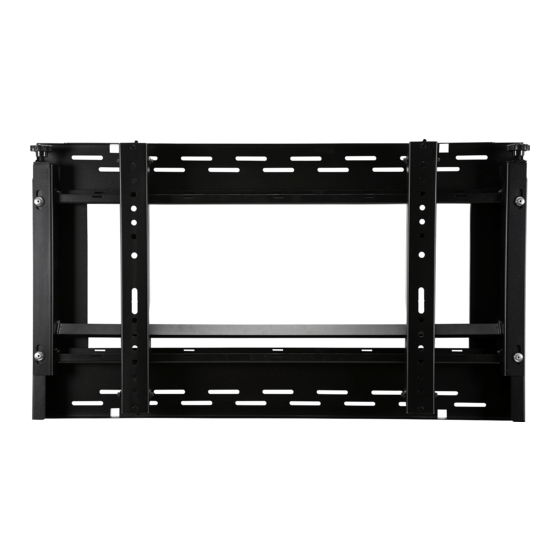
- Page 1 Installation and Assembly: Full Service Video Wall Mount Model: PD02VW MFS 46 55 P Designed for NEC MultiSync® 46” and 55” XUN/V, XS and P Series Manufactured by Peerless-AV Max UL Load Capacity: 125 lb (57 kg) 1 of 11...
-
Page 2: Table Of Contents
NOTE: Read entire instruction sheet before you start installation and assembly. WARNING • Do not begin to install your product until you have read and understood the instructions and warnings contained in this Installation Sheet. If you have any questions regarding any of the instructions or warnings, for US customers please call customer care at 1-800-865-2112, for all international customers, please contact your local distributor. -
Page 3: Parts List
Parts List Description Qty. Part # A pull out mount assembly 145 T1668 B adapter bracket 145 T1670 C mesh sleeve (not shown) 600 1014 D M5 x 10 mm socket pin type F screw 520 1164 E #14 x 2.5" hex head wood screw 5S1 015 C03 F concrete anchor 590 0320... -
Page 4: Installation To Wood Stud Wall
Installation to Wall Stud WARNING • Installer must verify that the supporting surface will safely support the combined load of the equipment and all attached hardware and components. • Tighten wood screws so that wall plate is fi rmly attached, but do not overtighten. Overtightening can damage the screws, greatly reducing their holding power. -
Page 5: Installation To Solid Concrete Or Cinder Block
Installation to Solid Concrete or Cinder Block WARNING • When installing wall mounts on cinder block, verify that you have a minimum of 1-3/8" (35 mm) of actual concrete thickness in the hole to be used for the concrete anchors. Do not drill into mortar joints! Be sure to mount in a solid part of the block, generally 1"... -
Page 6: Installing Tilt Brackets
Attaching Adapter Brackets to Display Attach adapter brackets (B) to back of display using four M6 x 12 mm socket pin screws (I) with nylon shoulder washer (H), or four M8 x 15 mm socket pin screws (J) as shown below. I or J Attaching Adapter Brackets to Display Carriage Attach adapter brackets (B) to display carriage. - Page 7 Pull Out Mount Assembly Adjustment Use legend below to determine position of display. NOTE: Each knob can be adjusted independently for fi ne tuning adjustments. Turn knob CLOCKWISE to raise side Turn knob COUNTER-CLOCKWISE to lower side ROTATE RIGHT ROTATE LEFT 7 of 11 ISSUED: 02-19-13 SHEET #: 145-9018-1...
-
Page 8: Display Adjustment
Adapter Bracket Adjustment Use legend below to determine position of display. NOTE: Each knob can be adjusted independently for fi ne tuning adjustments. Turn knob CLOCKWISE to move corner toward the wall Turn knob COUNTER-CLOCKWISE to move corner away from the wall TILT FORWARD BACK BACK... -
Page 9: Cable Management
Cable Management Display cables can be routed through top or bottom of pull-out mount assembly (A). NOTE: Use mesh sleeve (M) and cable ties (L) for cable management. NOTE: Cable ties and cable management slots on pull-out mount assembly (A) can be used to secure display cables. -
Page 10: Mounting And Removing Flat Panel Display
Open Adapter Brackets Open adapter brackets (B) by pulling down on front release strap while pulling bottom of display away from wall. NOTE: Once front release strap is pulled, adapter brackets (B) kick stand will engage. NOTE: Extended position is for service access only. The mount must be closed during normal use and operation. Close Adapter Brackets Slightly pull display away from wall to release kick stand while pulling down on back release straps on adapter brackets (B) as shown below. - Page 11 Pull-Out Mount Assembly (Optional) Security To prevent locking tabs from releasing, secure using two M5 x 10 mm socket pin type-F screws (D). 11 of 11 ISSUED: 02-19-13 SHEET #: 145-9018-1...
Need help?
Do you have a question about the Video Wall Mount PD02VW MFS 46 55 P and is the answer not in the manual?
Questions and answers