Advertisement
Available languages
Available languages
Quick Links
Operator's
Manual
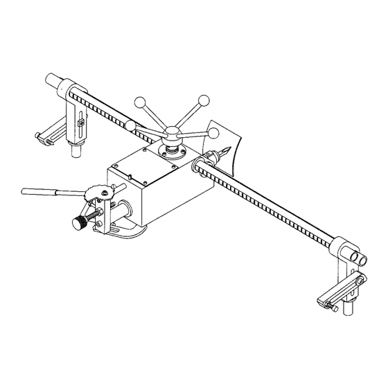
COPY CRAFTER
Model No.
351.249510
351.249520
CAUTION:
Read and follow all Safety
Rules and Operating
Instructions before First
Use of this Product.
• Safety
• Assembly
• Operation
• Maintenance
• Parts List
• EspaRol
Sears, Roebuck
and Co., Hoffman
Estates,
IL 60179 U.S.A.
www.seaPs.co_c_+,_man
18234,01 Draft (09/03/03)
Advertisement

Related Manuals for Craftsman 351.249510


Summary of Contents for Craftsman 351.249510
- Page 1 Operator's Manual COPY CRAFTER Model No. 351.249510 351.249520 • Safety CAUTION: • Assembly Read and follow all Safety • Operation Rules and Operating • Maintenance Instructions before First Use of this Product. • Parts List • EspaRol Sears, Roebuck and Co., Hoffman Estates, IL 60179 U.S.A.
- Page 2 • Keep visitors at a safe distance from work area. • Keep children out of workplace. Make workshop childproof. Use padlocks, master switches or remove switch keys to Warranty ......... prevent any unintentional use of power tools. Safety Rules ........TOOL SHOULD BE MAINTAINED Unpacking ........
-
Page 3: Think Safety
• Never place your fingers or hands in path of cutting tools. Your copy crafter is shippedcomplete in one carton.Separate all parts from packingmaterials and check each one with the • Never reach in back of the workpiece with either hand to unpackinglistto make certain all items are accountedfor before support the piece, remove wood scraps, or for any other discardingany packingmaterial,... - Page 4 Insert brasspin intothreaded hole at toolrest supportand then thread locking handle into the support. Place tool rest holderontotool rest supportand secure in Refer toFigures 1-9. positionusingone 8 x 30ram sockethead boltand spacer. CAUTION: Donot a ttempt assembly ifparts aremissing. Thread lockinghandle intotool rest holder. Use this manual toorder r eplacement parts.
- Page 5 • ,Secure brackets into tool rest bases using lockinghandles. INSTALL LEVER, HANDLES AND FINE ADJUSTMENT SCREW Refer to Figure 6. • Insert bushingsinto lever. Slide 8 x 20mm sockethead bolts Scre_ through bushings.Thread bolts into carriage and block. • Thread the four handles with knob intothe hub. Yoke "_'N3uide Follower Assembly...
-
Page 6: Specifications
In orderfor the copy crafter to function properly,the distance from the cuttingtool to the lathe spindle centadine must be Craftsman Copy Crefters provide the Craftsman Wood Lathes equal to the distancefrom the follower assembly to pattern with the capability to reproduce spindles and posts up to 38"... -
Page 7: Miscellaneous Operations
NOTE: Sharp corners and small grooves will only be partially duplicated by the copy crafter. The follower assembly will need to be removed. Using calipers, transfer measurements WARNING: Make certain that the lathe is disconnectedfrom from original to duplicate, and clean up grooves and corners using fine adjustment screw on carriage. - Page 8 SYMPTOM CORRECTIVE ACTION POSSIBLE CAUSE(S) Machine slows down while operating Applying too much pressure to workpiece Ease up on pressure Tool =chatters" during turning operation 1. Workpiece is too far out-of-round 1 True up the roundness of the workpiece before turning operation 2.
-
Page 9: Service Record
Service Record Craftsman Copy Crafter DATE MAINTENANCE PERFORMED REPLACEMENT PARTS REQUIRED... - Page 10 Model 351.249510 Figure 13 - Replacement Parts Illustration for Copy Crafter...
- Page 11 PART NO. DESCRIPTION QTY. PART NO. DESCRIPTION QTY. 18195.00 05331.00 5-0.8 x 12mm Socket Head Bolt Carriage 18196.00 18213.00 Bushing Bushing 18197.00 18214.00 Cam Plate Support Bar 18198.00 18215.00 Support Bar with Rack Plunger 02025.00 8-1.25 x 40mm Socket Head Bolt 18216.00 Spring 18199.00...
- Page 12 Model 351.249520 Figure 14 - Replacement Parts Illustration for Copy Crafter...
- Page 13 PART NO. DESCRIPTION PART NO. QTY. DESCRIPTION QTY. 18195.00 18212.00 Carriage Spring 18196.00 05331.00 5-0.8 x 12ram Socket Head Bolt Bushing 18197.00 18213.00 Support Bar Bushing 18198,00 18214,00 Cam Plate Support Bar with Rack 02025,00 8-1.25 x 40ram Socket Head Bolt 18215,00 Plunger 18199,00...
- Page 14 TRAZADOR • Use gafas de seguridad que cumplan con la norma ANSI Z87.1 de los Estados Unidos, Los anteojos comunes tienen lentes que s61o son resistentes al impacto. NO son anteojos Modelo No. de seguridad. 351.249510 • Use una m_scara para la cara o una m=_scara contra el polvo, sial utilizar la sierra se produce mucho polvo.
- Page 15 • No trate de alcanzar demasiado lejos. Mant6ngase flrrne y Pare su propia seguridad, lea todas les reglas y precauciones equilibrado. incluides en el manual del operador antes de utilizer la herra- rnienta. • Nunca se pare sobre la herramienta. Se pueden producir lesiones graves si la herramienta se vuelca o si entra en con- Pera proteger sus ojos, pbngase galas de seguridad que tacto con los centros sin intencibn.
- Page 16 INSTALE LA BASE DEL SOPORTE DE LA HERRAMIENTA Mar_ija (4) (MODELO 24951) Palanca con agarre Consuite la Figure 2, M Soporte pars patr6n (2) • Afloje la barfs de fijaci6n de la base del seporte de la herra- N Conjunto de la base del soporte de Is herramienta mienta y deslice la base del soporte de la hermmienta (su- (modelo 24951 solamente) ministrada con el torno) tan cerca del cabezal fijo corno sea...
- Page 17 • _oloque el conjunto del apoyo y puntal del soporte de la he- Puntal_ rramienta a una distancia aproximada de 30" de la base del Espaciador soporte de la herrarnienta suministrada con el tomo. Luego, las bases del soporte de la herramienta se p_:lr_n acorcar o separar m_s, dependiendo del Largode La pieze de trabajo.
- Page 18 • VeriRque la altura de la herTamienta de corte. La herramienta • Asegure el soporte de la deslizadera ala deslizadera utilizan- de corte debe quedar aproximadamente V_" por encirna de Is do los pernos de cabeza hueca de 8 x 25mm y las arandelas linea central de1 husillo.
- Page 19 DESCRIPClON AJUSTE Los Trazadores Craftsman les brindan a los Tomos para Madera Craftsman la capacidad de reproducir husUlos y soportes de Antes de comenzar, la herramienta de corte debe ester ajus- haste 38" de largo. El Modelo 24951 ha sido disefiado pare uso tada a aproxirnadamente Vs"...
- Page 20 LIMPIEZA • • Las medidas del soporte se transfleren a un material adecua- do ta[ como madera laminada de ¼" dispuasta y cortada en Mantenga la m=_quina y el taller limpios. No permita que el ase- una sierra de banda o una sierra de calar para contornear. rr[n se acumule en la herramienta.
- Page 21 SINTOMA CAUSA(S) POSIBLE(S) MEDIDA CORRECTIVA La mdquina disminuye ta velocidad durante Se aplica demasiada presibn ala pieza de Alivie la presi6n la operaci6n trabajo La herramienta "tintinea" durante la 1. La pieza de trabajo est_ demasiado 1. Rectifique la redondez de la pieza de deformada operaei6n trabajo antes de realizer la operaci6n...
- Page 22 ' Registro de Servicios Trazador de Craftsman FECHA MANTENIMIENTO EFECTUADO PARTES DE REPUESTO NECESARIAS...
- Page 23 NOTAS...
- Page 24 ii;i!;iii_ ii!;i;;ii!i;!;_;!iii ii!iiii!i!i!i!i_!iiiiii !i!i! !!!!i_! i:_!!%! !_!!! i i iii!i!i!!!i_ il _!iiiiiill i!iii_ii!!iii!!!!!iiii! i ii!iiiii i iiiiiiiiii iii_; ii i;ii ¸¸ _ Your Home For repair-in your home-of all major brand appliances, lawn and garden equipment, or heating and cooling systems, no matter who made it, no matter who sold it! _i ! i For the replacement...
Need help?
Do you have a question about the 351.249510 and is the answer not in the manual?
Questions and answers