COZY VCR501A-H Installation And Operating Instructions Manual
Gas-fired vented room heater
Hide thumbs
Also See for VCR501A-H:
- Installation and operating instructions manual (18 pages) ,
- Installation and operating instructions manual (18 pages)
Advertisement
INSTALLATION
AND
OPERATING
INSTRUCTIONS
P/N 80900-H
REV. 01/05
GAS
GAS
VC201A-H
VC351A-H
VC501A-H
VC701A-H_
VCR501A-H
VCR701A-H
VC202A-H
VC352A-H
VC502A-H
VC702A-H
IVCR352A-H
VCR502A-H
VCR702A-H
This appliance is equipped with a safety control system designed to protect against
improper venting of combustion products.
THIS UNIT IS NOT TO BE INSTALLED
IN MOBILE
HOMES.
WARNING:
If the information
in this manual
is not
followed
exactly,
a fire or explosion
may result
causing
property
damage,
personal
injury
or loss of
life.
Do not store or use gasoline or other flalr_nable vapors
and liquids in the vicinity of this or any other appliance.
WHAT
TO DO IF YOU
SMELL
GAS:
•
Do not try to light any appliance.
•
Do not touch any electrical switch; do not use any phone
in your building.
•
hnmediately
call your gas supplier from a neighbor's
phone. Follow the gas supplier's instructions.
•
If you cannot reach your gas supplier, call the fire
department.
INSTALLATION
AND SERVICE MUST BE
PERFORMED
BY A QUALIFIED
INSTALLER,
SERVICE AGENCY OR THE GAS SUPPLIER.
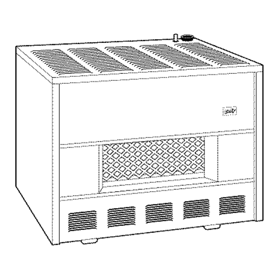
RADIANT FRONT
CLOSEDFRONT
The coating selected to provide longer life
to the heat exchanger may smoke slightly
upon initial firing. Provide adequate venti-
lation if this occurs.
WARNING:
Operation
of this heater when not connected to a properly installed
and maintained
venting system or tampering
with the vent safety shut-off system can result in Carbon
Monoxide
(CO) poisoning
and possible death.
This unit is not approved
for installation
in mobile
homes,
greenhouses,
or environments
involving
dusty,
wet, corrosive,
or explosive
conditions.
Such conditions
will invalidate
the warranD
T and may
create
unsafe
conditions.
Advertisement
Table of Contents

Subscribe to Our Youtube Channel
Related Manuals for COZY VCR501A-H


Summary of Contents for COZY VCR501A-H
- Page 1 INSTALLATION OPERATING INSTRUCTIONS P/N 80900-H REV. 01/05 VC201A-H VC351A-H VC501A-H VC701A-H_ VCR501A-H VCR701A-H VC202A-H VC352A-H VC502A-H VC702A-H IVCR352A-H VCR502A-H VCR702A-H This appliance is equipped with a safety control system designed to protect against improper venting of combustion products. THIS UNIT IS NOT TO BE INSTALLED IN MOBILE HOMES.
-
Page 2: Specifications
TABLE OF CONTENTS RADIANTS & GLASS PANELS... SPECIFICATIONS......BURNER ORIFICE & ORIFICE CHART..8 INTRODUCTION......PROPER BURNER FLAME ......VENTING........MAINTENANCE ........GAS StJPPLY........LIGHTING INSTRUCTIONS ....... LOCATION & SPECIAL PRECAI_IONS TROUBLE SHOOTING CHART .... 11,12 COMBUSTION & VENTILATION AIR ..BLOWER INSTRUCTIONS .... - Page 3 INTRODUCTION THIS IS A GAS-FIRED, GRAVITY VENTED ROOM HEATER THAT WILL OPERATE SAFELY AND PROVIDE AN EFFICIENT SOURCE OF HEAT WHEN INSTALLED, OPERATED AND MAINTAINED AS RECOMMENDED IN THESE INSTALLATION AND OPERATING INSTRUCTIONS. READ THESE INSTRCTIONS THOROUGHLY BEFORE INSTALLING, SERVICING, OR USING THIS APPLIANCE.
- Page 4 VENTING Ridge Chhnney -- FIGURE A FIGURE A CONNECTING THE VENT INTO Termination of vent must be AN EXISTING CHIMNEY securely guyed or braced if SAFE (See "Venting"} it extends more than five (5) NOTE: This lnay result feet above roof. Termination in the vent safely switch Seat around collar...
-
Page 5: Gas Supply
GAS SUPPLY LOCATION AND SPEICAL PRECAUTIONS This vented room heater must be connected to a gas supply Due to high temperatures the appliance should be capable of supplying the appliances full rated capacity. located out of traffic and away from furniture and Provide a 1/8 inch N.RT. - Page 6 COMBUSTION AND VENTILATION ALL COMBUSTION AIR FROM When installed, this gas appliance must be provided with fresh air for ADJACENT INDOOR SPACES combustion, ventilation, and dilution of hot flue gases. The minilnum required THROUGH INDOOR COMBUSTION volume of the area where the appliance is installed should be 50 cubic feet per AIR OPEN1NGS 1,000 btu/hr.
-
Page 7: Draft Diverter
DRAFT DIVERTER CLEARANCES If the area where the appliance is to be installed contains The draft diverter must be installed in the same atmospheric pressure zone as the combustion air supply for the main burner. carpeting, tile, or combustible materials, other than wood flooring, the appliance shall be installed on a metal plate (stoveboard), a wood panel, or other non-combustible... - Page 8 MAIN BURNER ORIFICE PILOT ADJUSTMENT This appliance was shipped from the factory with an orifice The pilot flame can be obsel-ved by opening the pilot lighting sized to give the correct gas input using the gas for which the hole cover. The pilot flame should surround the top 3/8 to L/_, heater was equipped.
- Page 9 CAUTION: Theremaybemomentary andspasmodic orange flashes i ntheflmne.Thisiscaused b ytheburning (;LEANING: To clean the front casing of your heater, it is of air bornedustparticles andis notto beconfused with only necessary to use a soft cloth. Light dust can be removed in this way. To obtain a polish or gloss, use a little light theyellowtippingwhichisastable orpermanent situation machine oil on the cloth.
- Page 10 MODELS: VC201A-H, VC202A-H, VC351A-H, VC352A-H, VC501A-H, VC502A-H, VC701A-H, VC702A-H, VCR351A-H, VCR352A-H, VCR501A-H, VCR502A-H, VCR701A-H, VCR702A-H YOUR SAFETY READ BEFORE LIGHTING WARNING: If you do not follow these instructions exactly, a fire or explosion may result causing property damage, personal injury or loss of life. A.
-
Page 11: Main Burner
TROUBLE SHOOTING CHART for qualified serviceman - MAIN BURNER SYMPTOM POSSIBLE CAUSES CORRECTIVE ACTION Flame too large 1. Defective operator section of gas valve. 1. Replace complete valve. 2. Burner orifice too large. 2. See orifice chart to determine the correct orifice size for your Model Number... - Page 12 TROUBLE SHOOTING CHART - POOR HEATING RESULTS - Cont'd. SYMPTOM POSSIBLE CAUSES CORRECTIVE ACTION i. Heater undersized. Not enough heat i. This is especially true when a dwelling or room is enlarged. Have the heat loss calculated and compare to the heater output (70% of input).
-
Page 13: Blower Installation
CHB-3 BLOWER INSTALLATION - (OPTIONAL) (STANDARD ON 70,000 BTU UNITS ONLY) STEP 1. Run black wire and white wire that comes froln bottom of junction box down through the heat shield. See Figure A. STEP 2. Insert junction box into opening in back of heater. Attach using four #8x 1/2" black screws provided. See Figure A. STEP3. -
Page 14: Wall Thermostat
TSK WALL STAT OPTIONAL (VC/VCR-H SERIES HEATERS) WALL THERMOSTAT INSTALLATION INSTRUCTIONS Your heater can be re-wired to operate with a millivolt wall thermostat by your installer. See wiring diagram below for correct wiring. NOTE: Do not disconnect the wire from the blocked flue switch to the "TH" terminal on the gas valve. STEP Disconnect wire leading from Part #70080 (Bulb Control Switch) from valve. -
Page 15: Models Included
Cozy heater. NOTE: Parts & NOTICE: When ordering any schematic drawings on current models component in the control train are shown at www.cozyheaters.com... - Page 16 $9.30 80006 $9.30 80006 $9.30 80006 $9.30 Cozy Logo Emblem 80007 $2.20 80007 $2.20 80007 $2.20 80007 $2.20 Clips, for Cozy Emblem 45175 $51.70 45640 $68.90 46460 $76.90 47180 $83.80 Casing Base Assembly 80009 $1.50 80009 $1.50 80009 $1.50 80009 $1.50...
- Page 17 IMPORTANT SAFETY BULLETIN ON YOUR GAS CONTROL AND PILOT LIGHT SYSTEM HEATING EQUIPMENT WHAT YOU DON'T KNOW CAN HURT YOU. Your pilot light system has been designed for safe and reliable operation. Although safe_" mechanisms are built-in, the potential for hazard exists.
- Page 18 Cozy Gas Fired Counterflow Furnace 10 Years Cozy Gas Fired Counterflow Direct Vent Furnace 10 Years Cozy Gas Fired Direct Vent Baseboard Furnace 10 Years Cozy Gas Fired Hi-Efficient Direct Vent Walt Furnace LOUISVILLE TIN AND STOVE COMPANY RO. Box2767 - Louisville, Kentucky40201-2767...
Need help?
Do you have a question about the VCR501A-H and is the answer not in the manual?
Questions and answers
how does the bulb control switch work?
The bulb control switch on the COZY VCR501A-H connects to the gas valve through the blocked flue switch. One wire from the bulb control switch goes to the blocked flue switch, and the other originally connected wire is cut and rerouted. A thermostat wire is connected from the gas valve’s "TH/PP" terminal to the blocked flue switch. This setup allows the bulb control switch to work with the thermostat and blocked flue switch to control the gas valve operation, helping regulate the heater based on temperature and safety conditions.
This answer is automatically generated