Table of Contents
Advertisement
Advertisement
Table of Contents

Related Manuals for Asus P5Q Turbo - Motherboard - ATX


Summary of Contents for Asus P5Q Turbo - Motherboard - ATX
- Page 1 P5Q Turbo...
- Page 2 Product warranty or service will not be extended if: (1) the product is repaired, modified or altered, unless such repair, modification of alteration is authorized in writing by ASUS; or (2) the serial number of the product is defaced or missing.
-
Page 3: Table Of Contents
Product introduction Welcome! ....................1-1 Package contents..................1-1 Special features..................1-2 1.3.1 Product highlights................ 1-2 1.3.2 ASUS special features ..............1-2 1.3.3 ASUS exclusive overclocking features........1-4 Chapter 2: Hardware information Before you proceed ................... 2-1 Motherboard overview ................2-2 2.2.1... -
Page 4: Contents
BIOS setup Knowing BIOS .................... 3-1 Updating BIOS .................... 3-1 3.2.1 ASUS Update utility..............3-2 3.2.2 ASUS EZ Flash 2 utility ............... 3-4 3.2.3 ASUS CrashFree BIOS 3 utility........... 3-5 BIOS setup program .................. 3-6 3.3.1 BIOS menu screen ..............3-6 3.3.2... - Page 5 3.8.2 Boot Settings Configuration ............3-28 3.8.3 Security ..................3-29 Tools menu ....................3-31 3.9.1 ASUS EZ Flash 2 ..............3-31 3.9.2 Drive Xpert Mode Update [Last Setting]........3-32 3.9.3 Express Gate [Enabled] ............3-33 3.9.4 ASUS O.C. Profile ..............3-34 3.9.5...
- Page 6 4.2.1 Running the support DVD ............4-1 4.2.2 Obtaining the software manuals..........4-2 Software information ................. 4-3 4.3.1 ASUS PC Probe II ............... 4-3 4.3.2 ASUS AI Suite ................4-4 4.3.3 ASUS EPU .................. 4-5 4.3.4 ASUS Fan Xpert................4-6 4.3.5...
-
Page 7: Notices
Notices Federal Communications Commission Statement This device complies with Part 15 of the FCC Rules. Operation is subject to the following two conditions: • This device may not cause harmful interference, and • This device must accept any interference received including interference that may cause undesired operation. -
Page 8: Safety Information
Safety information Electrical safety • To prevent electrical shock hazard, disconnect the power cable from the electrical outlet before relocating the system. • When adding or removing devices to or from the system, ensure that the power cables for the devices are unplugged before the signal cables are connected. If possible, disconnect all power cables from the existing system before you add a device. -
Page 9: About This Guide
Refer to the following sources for additional information and for product and software updates. ASUS websites The ASUS website provides updated information on ASUS hardware and software products. Refer to the ASUS contact information. Optional documentation Your product package may include optional documentation, such as warranty flyers, that may have been added by your dealer. -
Page 10: Conventions Used In This Guide
Conventions used in this guide To ensure that you perform certain tasks properly, take note of the following symbols used throughout this manual. DANGER/WARNING: Information to prevent injury to yourself when trying to complete a task. CAUTION: Information to prevent damage to the components when trying to complete a task. -
Page 11: P5Q Turbo Specifications Summary
4 x DIMM, max. 16 GB, DDR2 1300 / 1200 / 1066 / 800 / 667 MHz, non-ECC, un-buffered memory Dual channel memory architecture * Refer to www.asus.com or user manual for the Memory QVL (Qualified Vendors Lists). ** When you install a total memory of 4 GB capacity or more,... - Page 12 - ASUS 8-Phase Power Design - ASUS Express Gate ASUS Power Saving Solutions: - ASUS EPU ASUS Quiet Thermal Solutions: - ASUS Fanless Design: Stylish heatsink solution - ASUS Fan Xpert ASUS EZ DIY - ASUS Drive Xpert - ASUS CrashFree BIOS 3...
- Page 13 System Panel (Q-Connector) BIOS features 8 Mb AMI BIOS, PnP, DMI 2.0, WfM 2.0, SM BIOS 2.5, ACPI 3.0, ASUS EZ Flash 2, ASUS CrashFree BIOS 3 Manageability WOL by PME, WOR by PME, WOR by Ring, PXE Support DVD contents...
-
Page 15: Chapter 1: Product Introduction
® The motherboard delivers a host of new features and latest technologies, making it another standout in the long line of ASUS quality motherboards! Before you start installing the motherboard, and hardware devices on it, check the items in your package with the list below. -
Page 16: Special Features
Green ASUS This motherboard and its packaging comply with the European Union’s Restriction on the use of Hazardous Substances (RoHS). This is in line with the ASUS vision of creating environment-friendly and recyclable products/packaging to safeguard consumers’ health while minimizing the impact on the environment. -
Page 17: Express Gate
Fan Xpert ASUS Fan Xpert intelligently allows you to adjust both the CPU and chassis fan speeds according to different ambient temperatures caused by different climate conditions in different geographic regions and your PC’s loading. The built-in variety of useful profiles offer flexible controls of fan speed to achieve a quiet and cool environment. -
Page 18: Asus Exclusive Overclocking Features
ASUS EZ Flash 2 ASUS EZ Flash 2 is a user-friendly utility that allows you to update the BIOS without using a bootable floppy disk or an OS-based utility. -
Page 19: Chapter 2: Hardware Information
ON, in sleep mode, or in soft-off mode. This is a reminder that you should shut down the system and unplug the power cable before removing or plugging in any motherboard component. The illustration below shows the location of the onboard LED. ASUS P5Q Turbo... -
Page 20: Motherboard Overview
Motherboard overview 2.2.1 Motherboard layout Refer to 2.7 Connectors for more information about rear panel connectors and internal connectors. Chapter 2: Hardware information... -
Page 21: Layout Contents
IEEE 1394a port connector (10-1 pin IE1394_2) 2-32 Serial port connector (10-1 pin COM1) 2-32 Optical drive audio connector (4-pin CD) 2-31 Front panel audio connector (10-1 pin AAFP) 2-36 Digital audio connector (4-1 pin SPDIF_OUT) 2-34 ASUS P5Q Turbo... -
Page 22: Placement Direction
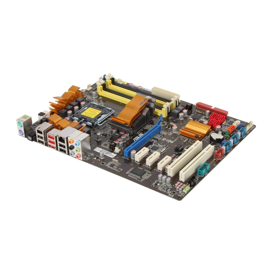
2.2.3 Placement direction When installing the motherboard, ensure that you place it into the chassis in the correct orientation. The edge with external ports goes to the rear part of the chassis as indicated in the image below. 2.2.4 Screw holes Place six screws into the holes indicated by circles to secure the motherboard to the chassis. -
Page 23: Central Processing Unit (Cpu)
Contact your retailer immediately if the PnP cap is missing, or if you see any damage to the PnP cap/socket contacts/motherboard components. ASUS will shoulder the cost of repair only if the damage is shipment/ transit-related. - Page 24 Press the load lever with your thumb Retention tab (A), then move it to the left (B) until it is released from the retention tab. To prevent damage to the socket pins, do not remove the PnP cap unless you are installing a CPU. Load lever Lift the load lever in the direction of the PnP cap...
- Page 25 To prevent contaminating the paste, DO NOT spread the paste with your finger directly. Close the load plate (A), then push the load lever (B) until it snaps into the retention tab. ASUS P5Q Turbo...
-
Page 26: Installing The Cpu Heatsink And Fan
2.3.2 Installing the CPU heatsink and fan The Intel LGA775 processor requires a specially designed heatsink and fan assembly to ® ensure optimum thermal condition and performance. • When you buy a boxed Intel ® processor, the package includes the CPU fan and heatsink assembly. -
Page 27: Uninstalling The Cpu Heatsink And Fan
Rotate each fastener counterclockwise. Pull up two fasteners at a time in a diagonal sequence to disengage the heatsink and fan assembly from the motherboard. Carefully remove the heatsink and fan assembly from the motherboard. ASUS P5Q Turbo... -
Page 28: System Memory
System memory 2.4.1 Overview The motherboard comes with four Double Data Rate 2 (DDR2) Dual Inline Memory Modules (DIMM) sockets. A DDR2 module has the same physical dimensions as a DDR DIMM but has a 240-pin footprint compared to the 184-pin DDR DIMM. DDR2 DIMMs are notched differently to prevent installation on a DDR DIMM socket. -
Page 29: Memory Configurations
3.5 Ai Tweaker menu for manual memory frequency adjustment. • For system stability, use a more efficient memory cooling system to support a full memory load (4 DIMMs) or overclocking condition. ASUS P5Q Turbo 2-11... - Page 30 P5Q Turbo Motherboard Qualified Vendors Lists (QVL) DDR2-1300 MHz capability DIMM socket support Chip Timing Vendor Part No. Size SS/DS Chip NO. Voltage (Optional) Brand Dimm (Bios) Team TXDD1024M1300HC6 1024MB Heat-Sink Package 6-6-6-18 2.35-2.45 V P5Q Turbo Motherboard Qualified Vendors Lists (QVL) DDR2-1200 MHz capability DIMM socket support...
- Page 31 2048MB(Kit of 2) DS GEIL GL2L64M088BA30EB 5-5-5-15 GEIL GE22GB800C4DC 2048MB(Kit of 2) DS N/A Heat-Sink Package 4-4-4-12 GEIL GE22GB800C5DC 2048MB(Kit of 2) DS N/A Heat-Sink Package 5-5-5-15 GEIL GX22GB6400DC 2048MB(Kit of 2) DS N/A Heat-Sink Package 5-5-5-15 ASUS P5Q Turbo 2-13...
- Page 32 P5Q Turbo Motherboard Qualified Vendors Lists (QVL) DDR2-800 MHz capability (cont.) DIMM socket support Chip Timing Vendor Part No. Size Chip NO. Voltage (Optional) Brand Dimm (Bios) GEIL GX22GB6400UDC 2048MB(Kit of 2) DS N/A Heat-Sink Package 4-4-4-12 GEIL GX22GB6400C4USC 2048MB DS N/A Heat-Sink Package GEIL...
- Page 33 Heat-Sink Package ELPIDA EBE51UD8AEFA-6E-E 512MB SS ELPIDA E5108AE-6E-E 1.7-1.9 G.SKILL F2-5400PHU2-2GBNT 2048MB(Kit of 2) DS G.Skill D264M8GCF 5-5-5-15 G.SKILL F2-5300CL5D-4GBMQ 4096MB(Kit of 2) DS N/A Heat-Sink Package 5-5-5-15 1.8-1.9 GEIL GX21GB5300SX 1024MB DS N/A Heat-Sink Package ASUS P5Q Turbo 2-15...
- Page 34 • C*: Supports four modules inserted into both the yellow and black slots as two pairs of dual-channel memory configuration. Visit the ASUS website at www.asus.com for the latest QVL. 2-16 Chapter 2: Hardware information...
-
Page 35: Installing A Dimm
DIMM. DIMM notch Support the DIMM lightly with your fingers when pressing the retaining clips. The DIMM might get damaged when it flips out with extra force. Remove the DIMM from the socket. ASUS P5Q Turbo 2-17... -
Page 36: Expansion Slots
Expansion slots In the future, you may need to install expansion cards. The following subsections describe the slots and the expansion cards that they support. Ensure to unplug the power cord before adding or removing expansion cards. Failure to do so may cause you physical injury and damage motherboard components. -
Page 37: Interrupt Assignments
– – – – SATA controller 1 – – – shared – – – – SATA controller 2 – – – – – – shared – IEEE 1394 – – – shared – – – – ASUS P5Q Turbo 2-19... -
Page 38: Pci Slots
2.5.4 PCI slots The PCI slots support cards such as a LAN card, SCSI card, USB card, and other cards that comply with PCI specifications. Refer to the figure below for the location of the slots. 2.5.5 PCI Express x1 slots This motherboard supports PCI Express x1 network cards, SCSI cards and other cards that comply with the PCI Express specifications. -
Page 39: Jumpers
• Due to the chipset behavior, AC power off is required to enable C.P.R. function. You must turn off and on the power supply or unplug and plug the power cord before rebooting the system. ASUS P5Q Turbo 2-21... - Page 40 CPU overvoltage setting (3-pin OV_CPU) This jumper allows you to enable or disable the advanced CPU overvoltage setting in BIOS. Read the following information before you change the jumper setting. Set to pins 1-2 to activate the advanced CPU overvoltage feature. OV_CPU Pins 2-3 (Default) up to 1.70V...
- Page 41 The USB device wake-up feature requires a power supply that can provide 500mA on the +5VSB lead for each USB port; otherwise, the system will not power up. • The total current consumed must NOT exceed the power supply capability (+5VSB) whether under normal condition or in sleep mode. ASUS P5Q Turbo 2-23...
-
Page 42: Connectors
Connectors 2.7.1 Rear panel connectors Rear panel connectors PS/2 mouse port (green) PS/2 keyboard port (purple) Optical S/PDIF Out port USB 2.0 ports 5 and 6 IEEE 1394a port External SATA port* USB 2.0 ports 3 and 4 USB 2.0 ports 1 and 2 LAN (RJ-45) port** 10. -
Page 43: Audio I/O Connections
Mic In Orange – – Center/Subwoofer Center/Subwoofer Black – Rear Speaker Out Rear Speaker Out Rear Speaker Out Gray – – – Side Speaker Out 2.7.2 Audio I/O connections Audio I/O ports Connect to Headphone and Mic ASUS P5Q Turbo 2-25... - Page 44 Connect to Stereo Speakers Connect to 2.1 channel Speakers Connect to 4.1 channel Speakers 2-26 Chapter 2: Hardware information...
- Page 45 Connect to 5.1 channel Speakers Connect to 7.1 channel Speakers ASUS P5Q Turbo 2-27...
-
Page 46: Internal Connectors
2.7.3 Internal connectors IDE connector (40-1 pin PRI_EIDE) The onboard IDE connector is for the Ultra DMA 133/100/66 signal cable. There are three connectors on each Ultra DMA 133/100/66 signal cable: blue, black, and gray. Connect the blue connector to the motherboard’s IDE connector, then select one of the following modes to configure your device. - Page 47 The Serial ATA RAID feature (RAID 0, 1, 5, and 10) is available only if you are using Windows ® XP SP2 or later version. • When using hot-plug and NCQ, set the Configure SATA as in the BIOS to [AHCI]. See section 3.4.2 Storage Configuration for details. ASUS P5Q Turbo 2-29...
- Page 48 SATA_E1 connector (orange, port 0) can be detected. • Clear all previous partitions in the hard disks before you proceed with any mode changes. Refer to 4.3.7 ASUS Drive Xpert for detailed application instructions. 2-30 Chapter 2: Hardware information...
- Page 49 Never connect a 1394 cable to the USB connectors. Doing so will damage the motherboard! You can connect the front panel USB cable to the ASUS Q-Connector (USB, blue) first, and then install the Q-Connector (USB) to the USB connector onboard if your chassis supports front panel USB ports.
- Page 50 IEEE 1394a port connector (10-1 pin IE1394_2) This connector is for an IEEE 1394a port. Connect the IEEE 1394a module cable to this connector, then install the module to a slot opening at the back of the system chassis. Never connect a USB cable to the IEEE 1394a connector. Doing so will damage the motherboard! The IEEE 1394a module cable is purchased separately.
- Page 51 Do not forget to connect the fan cables to the fan connectors. Insufficient air flow inside the system may damage the motherboard components. These are not jumpers! Do not place jumper caps on the fan connectors! Only the CPU_FAN, CHA_FAN 1 and CHA_FAN 2 connectors support the ASUS Fan Xpert feature. ASUS P5Q Turbo...
- Page 52 Chassis intrusion connector (4-1 pin CHASSIS) This connector is for a chassis-mounted intrusion detection sensor or switch. Connect one end of the chassis intrusion sensor or switch cable to this connector. The chassis intrusion sensor or switch sends a high-level signal to this connector when a chassis component is removed or replaced.
- Page 53 • If you are uncertain about the minimum power supply requirement for your system, refer to the Recommended Power Supply Wattage Calculator at http://support. asus.com/PowerSupplyCalculator/PSCalculator.aspx?SLanguage=en-us for details. ASUS P5Q Turbo 2-35...
- Page 54 Front panel audio connector (10-1 pin AAFP) This connector is for a chassis-mounted front panel audio I/O module that supports either HD Audio or legacy AC`97 audio standard. Connect one end of the front panel audio I/O module cable to this connector. •...
-
Page 55: System Panel Connector
Pressing the power switch for more than four seconds while the system is ON turns the system OFF. • Reset button (2-pin RESET) This 2-pin connector is for the chassis-mounted reset button for system reboot without turning off the system power. ASUS P5Q Turbo 2-37... - Page 56 ASUS Q-Connector (system panel) Use the ASUS Q-Connector to connect/disconnect the chassis front panel cables. To install the ASUS Q-Connector: Connect the front panel cables to the ASUS Q-Connector. Refer to the labels on the Q-Connector to know the detailed pin definitions, and then match them to their respective front panel cable labels.
-
Page 57: Starting Up For The First Time
BIOS setting. Pressing the power switch for more than four seconds lets the system enter the soft-off mode regardless of the BIOS setting. Refer to section 3.7 Power menu in Chapter 3 for details. ASUS P5Q Turbo 2-39... - Page 58 2-40 Chapter 2: Hardware information...
-
Page 59: Chapter 3: Bios Setup
® ASUS EZ Flash 2: Updates the BIOS using a floppy disk or USB flash disk. ASUS CrashFree BIOS utility: Restores the BIOS using the motherboard support DVD or a USB flash drive when the BIOS file fails or gets corrupted. -
Page 60: Asus Update Utility
3.2.1 ASUS Update utility The ASUS Update is a utility that allows you to manage, save, and update the motherboard BIOS in Windows environment. The ASUS Update utility allows you to: ® • Save the current BIOS file • Download the latest BIOS file from the Internet •... - Page 61 Auto Select. Click Next. Next. Follow the onscreen instructions to complete the update process. The ASUS Update utility is capable of updating itself through the Internet. Always update the utility to avail all its features. Updating the BIOS through a BIOS file...
-
Page 62: Asus Ez Flash 2 Utility
3.2.2 ASUS EZ Flash 2 utility The ASUS EZ Flash 2 feature allows you to update the BIOS without having to use a bootable floppy disk or an OS-based utility. Before you start using this utility, download the latest BIOS from the ASUS website at www.asus.com. -
Page 63: Asus Crashfree Bios 3 Utility
The BIOS file in the motherboard support DVD may be older than the BIOS file published on the ASUS official website. If you want to use the newer BIOS file, download the file at support.asus.com and save it to a USB flash drive. -
Page 64: Bios Setup Program
BIOS setup program A BIOS Setup program is provided for BIOS item modification. When you start up the computer, the system provides you with the opportunity to run this program. Press <Del> during the Power-On Self-Test (POST) to enter the Setup utility. Otherwise, POST continues with its test routines. -
Page 65: Navigation Keys
Press the Up/Down arrow keys or <Page Up> / <Page Down> keys to display the other items on the screen. Scroll bar 3.3.9 General help At the top right corner of the menu screen is a brief description of the selected item. ASUS P5Q Turbo... -
Page 66: Main Menu
Main menu When you enter the BIOS Setup program, the Main menu screen appears, giving you an overview of the basic system information. You can set the system time and date, BIOS language, and the type of floppy drive installed. Refer to 3.3.1 BIOS menu screen for information on the menu screen items and how to navigate through them. - Page 67 (Ultra DMA). Setting to [Auto] allows automatic selection of the DMA mode. SMART Monitoring [Auto] [Auto] Allows automatic selection of the S.M.A.R.T (Smart Monitoring, Analysis, and Reporting Technology). [Enabled] Enables the S.M.A.R.T feature. [Disabled] Disables the S.M.A.R.T feature. ASUS P5Q Turbo...
-
Page 68: Storage Configuration
32Bit Data Transfer [Enabled] [Enabled] Sets the IDE controller to combine two 16-bit reads from the hard disk into a single 32-bit double word transfer to the processor. This makes more efficient use of the PCI bus as fewer transactions are needed for the transfer of a particular amount of data. -
Page 69: Ahci Configuration
This menu gives you an overview of the general system specifications. The BIOS automatically detects the BIOS information, CPU specification, and system memory in this menu. BIOS SETUP UTILITY Main BIOS Information Version : 0206 Build Date: 02/13/09 Processor Type : Intel(R) Core(TM)2 Duo CPU @ 3.00GHz Speed : 3000MHz System Memory Usable Size : 512MB ASUS P5Q Turbo 3-11... -
Page 70: Ai Tweaker Menu
Ai Tweaker menu The Ai Tweaker menu items allow you to configure overclocking-related items. Be cautious when changing the settings of the Ai Tweaker menu items. Incorrect field values can cause the system to malfunction. The configuration options for this chapter vary depending on the CPU and DIMM model you installed on the motherboard. -
Page 71: Cpu Ratio Setting [Auto]
CAS# Latency [5 DRAM Clocks] Configuration options: [3 DRAM Clocks] [4 DRAM Clocks] – [11 DRAM Clocks] DRAM RAS# to CAS# Delay [5 DRAM Clocks] Configuration options: [3 DRAM Clocks] [4 DRAM Clocks] – [18 DRAM Clocks] ASUS P5Q Turbo 3-13... - Page 72 DRAM RAS# Precharge [5 DRAM Clocks] Configuration options: [3 DRAM Clocks] [4 DRAM Clocks] – [18 DRAM Clocks] DRAM RAS# Activate to Precharge Time [15 DRAM Clocks] Configuration options: [3 DRAM Clocks] [4 DRAM Clocks] – [34 DRAM Clocks] RAS# to RAS# Delay [Auto] Configuration options: [Auto] [1 DRAM Clocks] –...
-
Page 73: Dram Static Read Control [Auto]
Pull-In of CHA/B PH1/2/3/4 [Disabled] Set this item to [Enabled] to apply enhancement on DRAM Channel A and B, Phase 1 to 4. The number of phases is determined by DRAM frequency and FSB strap. Configuration options: [Disabled] [Enabled] ASUS P5Q Turbo 3-15... -
Page 74: Cpu Voltage [Auto]
3.5.13 CPU Voltage [Auto] Allows you to set the CPU VCore voltage. Use the <+> and <-> keys or the numeric keypad to enter the desired value. The values range from 0.85000V to 2.10000V* with a 0.00625V interval. • Refer to the CPU documentation before setting the CPU Vcore voltage. Setting a high VCore voltage may damage the CPU permanently, and setting a low VCore voltage may make the system unstable. -
Page 75: Sb Voltage [Auto]
NB Clock Skew item at the same time. Configuration options: [Auto] [Normal] [Delay 100ps]–[Delay 1500ps] 3.5.25 NB Clock Skew [Auto] Configuration options: [Auto] [Normal] [Delay 100ps]–[Delay 1500ps] 3.5.26 CPU Margin Enhancement [Optimized] Configuration options: [Optimized] [Compatible] [Performance Mode] ASUS P5Q Turbo 3-17... -
Page 76: Advanced Menu
Advanced menu The Advanced menu items allow you to change the settings for the CPU and other system devices. Be cautious when changing the settings of the Advanced menu items. Incorrect field values can cause the system to malfunction. BIOS SETUP UTILITY Main Ai Tweaker Advanced Power Boot Tools Exit CPU Configuration Configure CPU. - Page 77 Disables this function. Intel(R) C-STATE Tech [Disabled] The Intel C-State Technology allows the CPU to save more power under idle mode. Enable ® this item only when you install a C-State Technology-supported CPU. Configuration options: [Disabled] [Enabled] ASUS P5Q Turbo 3-19...
-
Page 78: Chipset
3.6.2 Chipset The Chipset menu allows you to change the advanced chipset settings. Select an item then press <Enter> to display the submenu. BIOS SETUP UTILITY Advanced Advanced Chipset Settings Configure North Bridge features. WARMING: S etting wrong values in below sections may cause system to malfunction. North Bridge Configuration North Bridge Chipset Configuration BIOS SETUP UTILITY Advanced North Bridge Chipset Configuration... -
Page 79: Onboard Devices Configuration
[Disabled] Disables the LAN Boot ROM. Onboard 1394 Controller [Enabled] [Enabled] Enables the onboard IEEE 1394a controller. [Disabled] Disables the controller. Serial Port1 Address [3F8/IRQ4] Allows you to select the Serial Port1 base address. Configuration options: [Disabled] [3F8/IRQ4] [2F8/IRQ3] [3E8/IRQ4] [2E8/IRQ3] ASUS P5Q Turbo 3-21... -
Page 80: Usb Configuration
3.6.4 USB Configuration The items in this menu allow you to change the USB-related features. Select an item then press <Enter> to display the configuration options. BIOS SETUP UTILITY Advanced USB Configuration Enable support for Options all USB ports. USB Devices Enabled: Disabled None Enabled USB Functions [Enabled] USB 2.0 Controller [Enabled] USB 2.0 Controller Mode [HiSpeed]... -
Page 81: Pcipnp
When set to [Yes] and if you install a Plug and Play operating system, the operating system configures the Plug and Play devices not required for boot. [No] When set to [No], BIOS configures all the devices in the system. ASUS P5Q Turbo 3-23... -
Page 82: Power Menu
Power menu The Power menu items allow you to change the settings for the Advanced Power Management (APM). Select an item then press <Enter> to display the configuration options. BIOS SETUP UTILITY Main Ai Tweaker Advanced Power Boot Tools Exit Select the ACPI state used for System Suspend Mode [Auto] Repost Video on S3 Resume [No] Suspend. ACPI 2.0 Support [Disabled] ACPI APIC Support [Enabled] APM Configuration... -
Page 83: Apm Configuration
Power On By PS/2 Mouse [Disabled] [Disabled] Disables the Power On by a PS/2 mouse. [Enabled] Enables the Power On by a PS/2 mouse. This feature requires an ATX power supply that provides at least 1A on the +5VSB lead. ASUS P5Q Turbo 3-25... -
Page 84: Hardware Monitor
3.7.6 Hardware Monitor BIOS SETUP UTILITY Power Hardware Monitor CPU Temperature CPU Temperature [42ºC/107.5ºF] MB Temperature [33ºC/91ºF] CPU Fan Speed [4856RPM] CPU Q-Fan Control [Disabled] Chassis Fan 1 Speed [N/A] Chassis Fan 2 Speed [N/A] Chassis Q-Fan Control [Disabled] Power Fan Speed [N/A] CPU Voltage [ 1.234V] 3.3V Voltage [ 3.320V] 5V Voltage [ 5.026V] 12V Voltage [11.787V] CPU/MB Temperature [xxxºC/xxxºF] The onboard hardware monitor automatically detects and displays the CPU and motherboard temperatures. -
Page 85: Boot Menu
These items specify the boot device priority sequence from the available devices. The number of device items that appears on the screen depends on the number of devices installed in the system. Configuration options: [Removable Dev.] [Hard Drive] [ATAPI CD-ROM] [Disabled] ASUS P5Q Turbo 3-27... -
Page 86: Boot Settings Configuration
Enables the full screen logo display feature. [Disabled] Disables the full screen logo display feature. Set this item to [Enabled] to use the ASUS MyLogo 2™ feature. AddOn ROM Display Mode [Force BIOS] [Force BIOS] The third-party ROM messages will be forced to display during the boot sequence. -
Page 87: Security
Time Clock (RTC) RAM. See section 2.6 Jumpers for information on how to erase the RTC RAM. After you have set a supervisor password, the other items appear to allow you to change other security settings. ASUS P5Q Turbo 3-29... - Page 88 BIOS SETUP UTILITY Boot Security Settings <Enter> to change password. Supervisor Password : Installed <Enter> again to User Password : Installed disabled password. Change Supervisor Password User Access Level [Full Access] Change User Password Clear User Password Password Check [Setup] User Access Level [Full Access] This item allows you to select the access restriction to the Setup items. [No Access] Prevents user access to the Setup utility. [View Only] Allows access but does not allow change to any field.
-
Page 89: Tools Menu
3.9.1 ASUS EZ Flash 2 Allows you to run ASUS EZ Flash 2. When you press <Enter>, a confirmation message appears. Use the left/right arrow key to select between [Yes] or [No], then press <Enter> to confirm your choice. -
Page 90: Drive Xpert Mode Update [Last Setting]
3.9.2 Drive Xpert Mode Update [Last Setting] Set this item to [Mode Change] to show further settings of the Drive Xpert function. Configuration options: [Last Setting] [Mode Change] The following items appear only when you set Drive Xpert Mode Update to [Mode Change]. -
Page 91: Express Gate [Enabled]
3.9.3 Express Gate [Enabled] Allows you to enable or disable the ASUS Express Gate feature. The ASUS Express Gate feature is a unique instant-on environment that provides quick access to the Internet browser and Skype. Configuration options: [Enabled] [Disabled] Enter OS Timer [10 Seconds] Sets countdown duration that the system waits at the Express Gate’s first screen... -
Page 92: Asus O.c. Profile
3.9.4 ASUS O.C. Profile This item allows you to store or load multiple BIOS settings. BIOS SETUP UTILITY Tools O.C. PROFILE Configuration Save BIOS settings to Profile 1 O.C. Profile 1 Status : Not Installed O.C. Profile 2 Status : Not Installed Save to Profile 1... -
Page 93: Ai Net 2
AI NET 2 cable during POST. Pair Status Length Check Atheros LAN cable [Disabled] Check Atheros LAN Cable [Disabled] [Disabled] BIOS will not check the Atheros LAN cable during the Power-On Self-Test (POST). [Enabled] BIOS checks the Atheros LAN cable during the Power-On Self-Test (POST). ASUS P5Q Turbo 3-35... -
Page 94: Exit Menu
3.10 Exit menu The Exit menu items allow you to load the optimal or failsafe default values for the BIOS items, and save or discard your changes to the BIOS items. BIOS SETUP UTILITY Main Ai Tweaker Advanced Power Boot Tools Exit Exit system setup Exit & Save Changes after saving the Exit & Discard Changes changes. Discard Changes F10 key can be used Load Setup Defaults for this operation. -
Page 95: Chapter 4: Software Support
The contents of the support DVD are subject to change at any time without notice. Visit the ASUS website at www.asus.com for updates. 4.2.1 Running the support DVD Place the support DVD into the optical drive. -
Page 96: Obtaining The Software Manuals
4.2.2 Obtaining the software manuals The software manuals are included in the support DVD. Follow the instructions below to get the necessary software manuals. The software manual files are in Portable Document Format (PDF). Install the Adobe ® Acrobat Reader from the Utilities menu before opening the files. ®... -
Page 97: Software Information
Launching PC Probe II Install PC Probe II from the motherboard support DVD. Launch PC Probe II by clicking Start > All Programs > ASUS > PC Probe II > PC Probe II v1.xx.xx. The PC Probe II main window appears. -
Page 98: Asus Ai Suite
Launching AI Suite Install AI Suite from the motherboard support DVD. Launch AI Suite by clicking Start > All Programs > ASUS > AI Suite > AI Suite v1.xx. xx. The AI Suite main window appears. The AI Suite icon appears in the Windows notification area. -
Page 99: Asus Epu
4.3.3 ASUS EPU ASUS EPU is an energy-efficient tool that provides you with a total system power-saving solution. It detects the current computer loading and intelligently adjusts the power in real-time. With auto phase switching for components, the EPU automatically provides the most appropriate power usage via intelligent acceleration and overclocking. -
Page 100: Asus Fan Xpert
4.3.4 ASUS Fan Xpert Asus Fan Xpert allows you to adjust both the CPU and chassis fan speeds according to different ambient temperatures and your PC’s system loading. The various fan profiles offer flexible controls of fan speeds to achieve a quiet and cool system environment. -
Page 101: Asus Turbov
4.3.5 ASUS TurboV ASUS TurboV allows you to easily overclock without exiting or rebooting the OS, and set up the best O.C. settings for different scenarios. Refer to the CPU documentation before adjusting CPU voltage settings. Setting a high voltage may damage the CPU permanently, and setting a low voltage may make the system unstable. -
Page 102: Asus Turbo Key
4.3.6 ASUS Turbo Key ASUS Turbo Key allows the user to turn the PC power button into a physical overclocking button. After the easy setup, Turbo Key can boost performances without interrupting ongoing work or games—with just one touch! Launching ASUS Turbo Key Install ASUS Turbo Key from the motherboard support DVD. -
Page 103: Asus Drive Xpert
Super Speed erases all original data/partitions in both hard disks. You may use Drive Xpert function in Express Gate and BIOS setup environments. Refer to the software manual in the support DVD or visit the ASUS website at www.asus.com for detailed software configuration. -
Page 104: Asus Express Gate
4.3.8 ASUS Express Gate ASUS Express Gate is an instant-on environment that gives you quick access to the Internet, Skype, and viewing your pictures. Within a few seconds of powering on your computer, you will be at the Express Gate menu where you can start the web browser, Skype, or other Express Gate applications. -
Page 105: Audio Configurations
VIA HD Audio Deck for Windows XP Display panel and volume control Minimize button Configuration options Control settings window Refer to the software manual in the support DVD or visit the ASUS website at www.asus.com for detailed software configuration. ASUS P5Q Turbo 4-11... -
Page 106: Raid Configurations
RAID configurations The motherboard comes with the Intel ICH10R Southbridge controller that supports RAID 0, ® RAID 1, RAID 10, and RAID 5 for six independent Serial ATA channels. 4.4.1 RAID definitions RAID 0 (Data striping) optimizes two identical hard disk drives to read and write data in parallel, interleaved stacks. -
Page 107: Setting The Raid Item In Bios
The RAID BIOS setup screens shown in this section are for reference only and may not exactly match the items on your screen. The utility supports maximum four hard disk drives for RAID configuration. ASUS P5Q Turbo 4-13... - Page 108 Creating a RAID set To create a RAID set: From the utility main menu, select 1. Create RAID Volume and press <Enter>. The following screen appears: Intel(R) Matrix Storage Manager option ROM v8.0.0.1038 ICH10R wRAID5 Copyright(C) 2003-08 Intel Corporation. All Rights Reserved. [ CREATE VOLUME MENU ] Name: Volume0 RAID Level: RAID0(Stripe) Disks: Select Disks Strip Size: 128KB Capacity: 0.0 GB Create Volume [ HELP ] Enter a unique volume name that has no special characters and is 16 characters or less. [↑↓]Change [TAB]-Next [ESC]-Previous Menu [ENTER]-Select Enter a name for the RAID set and press <Enter>. When the RAID Level item is selected, press the up/down arrow key to select a RAID level to create, and then press <Enter>.
-
Page 109: Deleting A Raid Set
RAID set. To delete a RAID set: From the utility main menu, select 2. Delete RAID Volume and press <Enter>. The following screen appears: Intel(R) Matrix Storage Manager option ROM v8.0.0.1038 ICH10R wRAID5 Copyright(C) 2003-08 Intel Corporation. All Rights Reserved. [ DELETE VOLUME MENU ] Name Level Drives Capacity Status Bootable Volume0 RAID0(Stripe) 2 298.0GB Normal Yes [ HELP ] Deleting a volume will reset the disks to non-RAID. WARNING: ALL DISK DATA WILL BE DELETED. [↑↓]-Select [ESC]-Previous Menu [DEL]-Delete Volume ASUS P5Q Turbo 4-15... - Page 110 Use the up/down arrow key to select the RAID set you want to delete, and then press <Del>. The following warning message appears: [ DELETE VOLUME VERIFICATION ] ALL DATA IN THE VOLUME WILL BE LOST! Are you sure you want to delete volume “Volume0”? (Y/N): Press <Y> to delete the RAID set and return to the utility main menu, or press <N> to return to the DELETE VOLUME menu.
-
Page 111: Creating A Raid Driver Disk
Intel ICH10R RAID driver disk. ® Insert a floppy disk into the USB floppy disk drive. Follow the succeeding screen instructions to complete the process. Write-protect the floppy disk to avoid a computer virus infection. ASUS P5Q Turbo 4-17... - Page 112 To install the RAID driver in Windows ® During the OS installation, the system prompts you to press the F6 key to install third-party SCSI or RAID driver. Press <F6>, and then insert the floppy disk with RAID driver into the USB floppy disk drive.
-
Page 113: Using A Usb Floppy Disk Drive
Product ID (PID) are displayed. Browse the contents of the RAID driver disk to locate the file txtsetup.oem. Double-click the file. A window appears, allowing you to select the program for opening the oem file. ASUS P5Q Turbo 4-19... - Page 114 Use Notepad to open the file. Find the [HardwareIds.scsi.iaAHCI_ICH10R] and [HardwareIds.scsi.iastor_ICH8RICH9RICH10RDO] sections in the txtsetup.oem file. Type the following line to the bottom of the two sections: id = “USB\VID_xxxx&PID_xxxx”, “usbstor” Add the same line to both sections. The VID and PID vary with different vendors. Save and exit the file.
Need help?
Do you have a question about the P5Q Turbo - Motherboard - ATX and is the answer not in the manual?
Questions and answers